1
TOSHIBA V 856 B
U-View Limited
General Information
V3 Mechanism - Also Covers V 857B
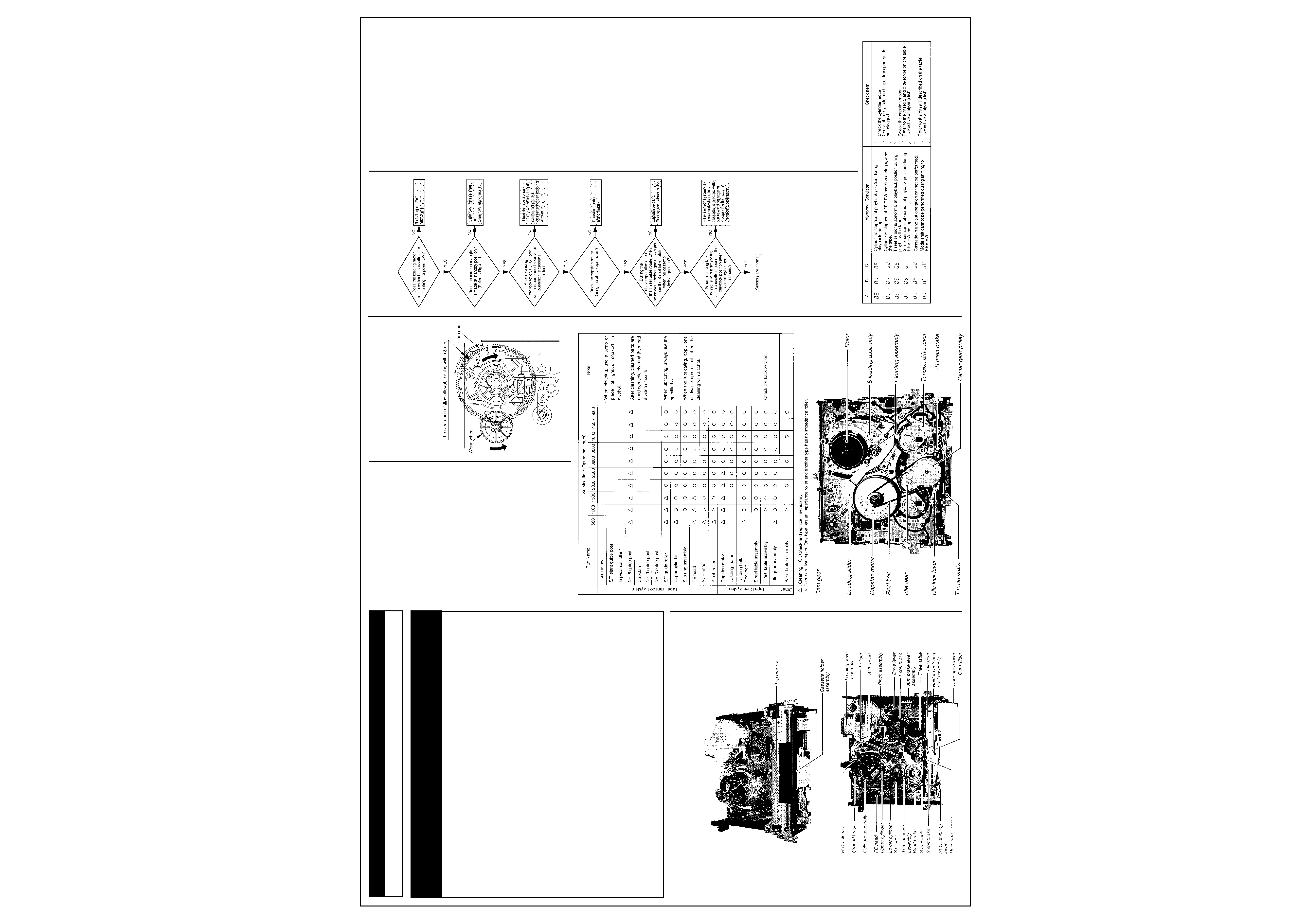
1-4. V3 Mechanism Check Method
If the abnormal condition is caused by the
mechanism itself, analyze the cause according
to the following procedures.
1-4-1. External Appearance check
1) Check whether there are foreign matters or
not inside the VTR.
2) Check whether the cylinder and the guides for
tape transport system are contaminated.
Fig. 4-1-1
1-4-2. Motor Sensor System check
Check whether some abnormalities are found in
the motor or the sensor system (including
control circuits) according to the flow chart.
1-4-3. Abnormality Analysis by Self-check
Function
The unit used V3 mechanism has a self-check
function.
The self-check function works as a system
which stored some abnormal condition. So, use
this function to try to analyze the cause(s).
For the data display method and the content of
the data, refer to the self-check function in item
2-3.
Table 4-3-1
Note:
· Abnormal data is displayed only when the first
abnormal condition occurs, and is not
displayed in the second time. Accordingly, the
claim from customers and the actual data
displayed may be different.
· The data is stored only when the power turns
off after occurring the abnormality
condition(s). The data is not stored when the
unit operation is recovered by the microcom-
puter.
· After repairing, initialize the data by pressing
the [COUNTER RESET] button while
displaying the abnormal mode.
The typical examples in abnormal condition
are shown (See Table 4-3-1).
1-4-4. Check by Defective Analyzing List
If the abnormality causes the mechanism
abnormal condition, presume, confirm and treat
the defective according to the "Defective
analyzing list" in Table 4-4-1.
1) Manual mechanism operation (mode shift)
method
Push in the lock lever R and L manually and turn
the worm wheel counterclockwise as shown in
Fig. 4-1-1. The cam gear is turned clockwise
and the mode shifts to the direction where the
loading operation can be performed. So, check
the mechanism condition in the defective
mechanism position when the abnoimality
occurs.
2) Defective parts replacement
When a defective occurs due to the defective
part(s) and the part(s) is replaced, take care the
following items.
· Especially as for the mechanical parts
requiring the phase alignment, take care of the
part replacement E.g.. Assembling mode, phase
alignment mark and etc.
· As for the part(s) requiring lubricant such as a
specified amount of oil or grease, apply grease
or oil according to the instructions and do not
stick grease or oil to the portions without
allowing to stick it (especially in removal and
assembly).
3) Check after treating the defective
After replacing a defective part andlor aligning a
part, first check the mechanism operation
manually and confirm that no problem occurs,
and then mount the mechanical (leek, turn the
power ON and check the mechanism operation.
Note:
· After replacing the defective parts according
to the procedure of the treatment method for
the damage and phase shift of mechanical
part", check the operation of the mechanism
again, since the same (or similar) defective
problem may occur due to other serious
cause (in mechanism or electrical circuit)
when performing the actual total check with
turning the power on.
Continues Next Page...
Recommended Safety Parts
Item
Part No.
Description
0001C
70061667
Owners Manual English
0014C
70012604
Power Cord
0250
70051879
Front Panel
0350
70051766
Bottom Plate
0400
70824403
Top Cover
RN441
70041571
Res, Fusible
18
J 0. 3W
RS045
70041671
Res, Fusible
18
J 0. 3W
RT089
70040122
Res, Carbon
1
J 0. 3W
RW012
70041074
Res, Fusible
27
J 0. 3W
RW021
70040122
Res, Carbon
1
J 0. 3W
RW030
70041116
Res, Fusible
39
J 0. 3W
0060M
70051878
Back Panel
LP002
70011949
Line Filter
LP020
70012519
Power Transformer SRN2924ED
CP001
70042150
Cap, Plastic
100nF
M
CP002
70041888
Cap Electrolytic
100
µF
M 385V
CP003
70051555
Cap
2.2nF
400V
RP018
70042048
Res, Metal
0.82
K 0. 4W
RP021
70041673
Bes, Fusible
2. 2k
J 0. 3W
RP041
70042246
Res, Fusible
0. 22
RP058
70042046
Res, Chip
100
J 0. 3W
RP071
70041073
Res, Fusible
22
J 0. 3W
RP091
70042248
Res
1. 5
RP092
70041116
Res, Fusible
39
J 0. 3W
RP100
70041946
Res
680
420V
BP001
70011176
Inlet
FP001
70010445
Fuse, 1A, 250V
(V-856B Only)
0001C
70061667
Owners Mnual English 1
0014C
70012504
Power Cord
0250
70051879
Front Panel
0350
70051756
Bottom Plate
0400
70824403
Top Cover
RP092
70041116
Res, Fusible 39
J 0. 3W
0001C
70061929
Owners Manual English
0014C
70012731
Power Cord
0250
70051996
Front Panel
RP092
70040125
Res, Carbon 47
J 0. 3W
1-2. Servicing Jig List
Alignment tape
70909409 (ST-C6)
70909410 (ST-C7)
Back tension cassette gauge
70909103
Torque cassette gauge (KT-300NR)
70909199
Taper nut driver
70909228
VTR cleaning kit
VTR lubrication kit
Grease
Note: Conventional alignment tapes ST-C1
(70909227) and ST-C3 (70909264) can be used
partially.
1-3. Main Parts Servicing Time
· Part replacement time differs from servicing
life time of each part.
· Following table is prepared based on a
standard condition (room temperature, room
humidity). The replacement time will be varied
depending upon operation environment, using
methods, operation duty, etc.
· Particularly, life of the upper cylinder depends
upon operation conditions.
Adjustment Procedures
1. Mechanical Adjustment
1-1. Mechanical Parts Location
Top View
Bottom View
2
TOSHIBA V 856 B
www.u-view.co.uk
Mechanical Adjustments Cont'd
Table 4-4-1 Defective Analyzing List
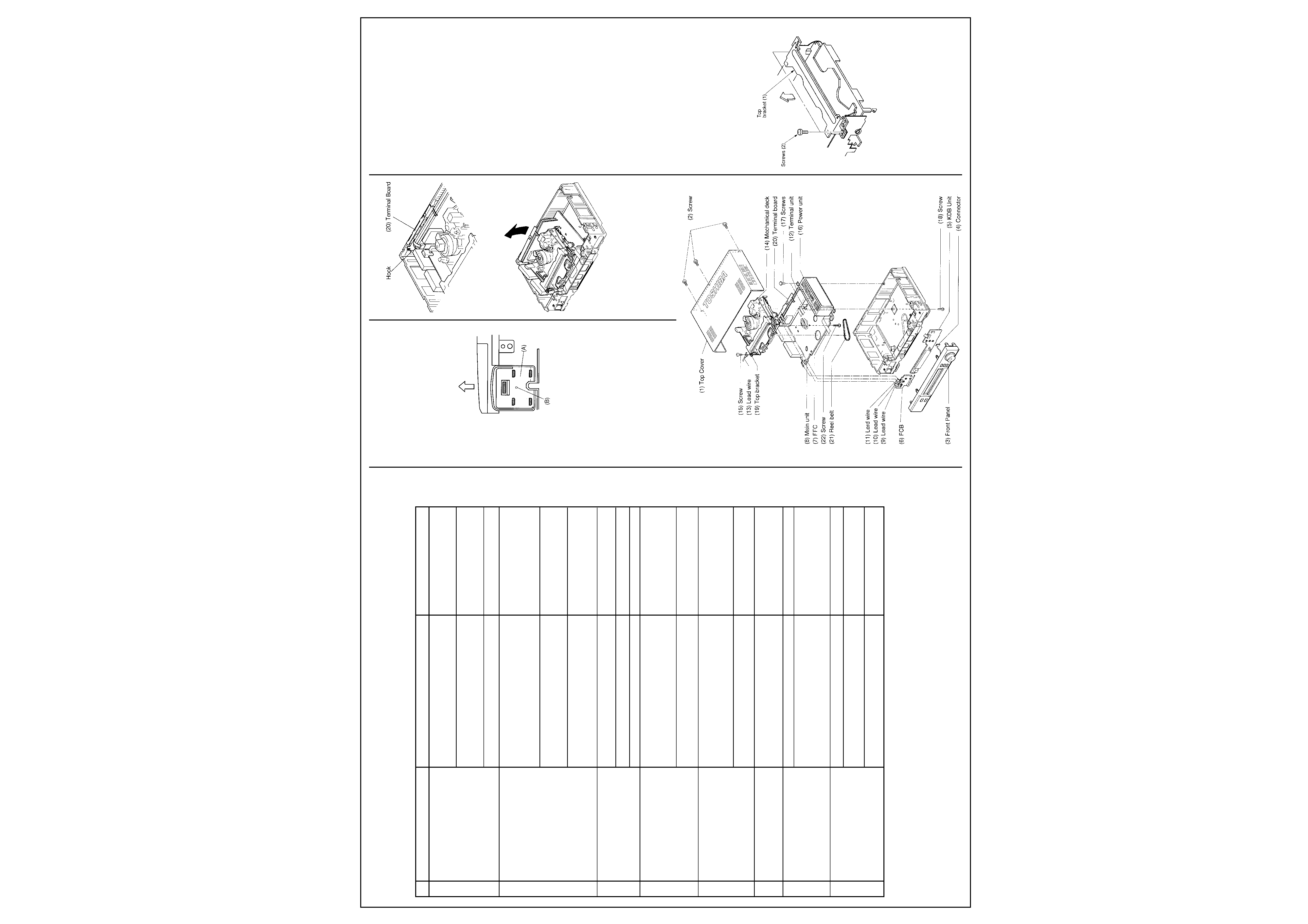
1-5. Mechanical Deck Removal and Mounting
1-5-1. Mechanical Deck Removal
1. Remove three screws (2) mounting the top
cover (1) and unlock two hooks at both left
and right of the rear side, then remove the top
cover sliding backward and lifting upward.
2. Remove left and right insulators. Insulators
(A) can be remove by unfastening the hook of
the chassis inserting a bar into the hole (B)
located on the bottom, and by sliding it to the
arrow mark direction.
Fig. 5-1-1
3. Remove the connector (4) (KDB unit side) of
the JSB unit, and remove the front panel (3).
4. Remove the FFC (7) connecting between
main unit (8) and KDB unit (5), lead wires (9)
and (10) connecting between terminal unit (1
2) and FCB unit (6), lead wire (11) connecting
between main unit (8) and FCB unit (6).
Remove lead wire (13) between a mechanical
deck (14) and FCB unit (6) by loosening
screw (15).
Note:
In this case, remove FFC (7) on KDB unit (5)
side, lead wire (9) on FCB unit (6) side and lead
wire (1 3) on mechanical deck (14) side.
6. Remove a screw (1 8) securing the mechani-
cal deck (14).
Fig. 5-1-2
7. Undo the hook of the Terminal board (20) by
pressing it and lift it up.
Fig. 5-1-3
8. Remove the mechanical deck (14) with main
unit (8) from the chassis liftino its rear side
slightly and pulling it upward.
Fig. 5-1-4
Note:
When pulling the top bracket upward, take care
not to deform the reinforcement plate located
below the F/L assembly.
9. Remove the lead wire connecting between
the mechanical (leek (14) and the main Linit
(8).
10.Tum over the mechanical (leek (14).
11.Remove the reel belt (21) and one screw
(22).
12.Remove four claws securing the mechanical
deck (14) and the main unit (8), and then
remove the main unit (8) pulling upward.
1-5-2. Mechanical Deck Mounting
Turn over the mechanical deck and lower the
main unit vertically adjusting the tape end
sensor and etc. to the holes.
Note:
· Adjust the rotor of the cylinder motor and the
stator of the main unit,and then lower the
main unit further more till four claws catch the
mechanical deck completely.
· Take care not to damage the rotor and the
stator.
· When locking the claw of the front right side to
the main unit, turn the REC inhibit lever so as
not to damage the switch.
2. Mount the mechanical deck on the chassis in
reverse order of removal.
Note:
When mounting the front panel, mount it with its
door fully open.
1-5-3.Confirmation of Each Operation Mode
without Cassette
1. Shut out the light to the start/end sensor.
2. Release the both sides of the lock lever and
make a slot-in condition.
3. Turn the reel table manually located on the
opposite side of the rotating reel table.
4. In this condition, confirmation of each
operation mode can be performed.
Note:
When turning the opposite side reel table of the
rotating reel table manually in playback, FF/
REW mode, and sending no reel pulse. the auto
eject or power off function is performed.
1-6. Main Parts Replacement
1-6-1. Top Bracket Replacement
1. Remove two securing screws (2) on the top
bracket (1).
2. Remove the top bracket (1) lifting in the
direction shown by the arrow.
Fig. 6-1-1
Continues Next Page...
Case
Detective Phenomenon (Main Items)
Presumed Cause (Main Cause)
Check Method
1
Power does not turn on. Loading
<General>
Check mode shitt "Cassette out
operation is defective. Mode shift
Mechanical stops due to mechanical phase
FE/REW position" can be pertormed
operation is defective.
unmatching.
when turning worm wheel.
Loading operation is not performed.
Loading motor does not rotate.
Check loading motor whether it turns by
(Loading motor is defective or circuit is
the outer power supply (12.5V).
detective.)
Unloading operation is not performed.
S reel does not wind the tape.
Refer to case 3 in this table.
2
Playback operation is not performed.
<General>
Check mechanical position.
Playback operation is defective.
Main brake is not released. (ON)
T soft brake is not released. (ON)
Idler does not swing.
Pinch does not press.
Capstan motor does not rotate.
Check capstan motor.
(Capstan motor is defective or circuit is
defective.)
Playback picture does not appear.
<In case of no mechanical problem>
Check cylinder assembly.
Video recording can not be
Cylinder is defective.
performed.
(Circuit is defective.)
3
Playback interruption.
Reel rotation detection is defective.
Check sensor output.
Detective phenomenon during
(Sensor is defective. Circuit is defective.)
playback.
Recording interruption.
Idler does not swing.
Check mechanical position.
Reel belt is removed.
Check the reel belt is removed or not.
4
FF operation is not performed.
Main brake is not released. (ON)
Check mechanical position.
FF operation is defective.
T soft brake is not released. (ON)
REW operation is not performed.
Idler does not swing.
REW operation is defective.
Pinch is not released.
Others: REV/FF is not performed.
Others: REV/FF is defective.
Capstan motor does not rotate.
Check capstan motor.
(Capstan motor is defective or circuit is defective.)
5
REVIEW is not performed.
Main brake is not released. (ON)
Check mechanical position.
T soft brake is not actuated.
Idler does not turn.
Pinch does not press.
Capstan motor does not rotate.
Check capstan motor.
(Capstan motor is defective or circuit is defective.)
6
Slot-in is not performed.
<General>
Check mechanical position.
Cassette can not be inserted.
When the F/L is mounted on the
mechanical deck the position is not correct.
7
Capstan servo does not work.
Capstan motor is defective.
Check capstan motor.
Capstan servo is uneven.
Tape speed is fast.
ACE head control output is defective.
Check ACE head.
Tape speed is slow.
(Circuit is defective.)
Check CTL output.
Tape speed is uneven.
EG pulse is not output.
8
Audio output does not come out.
ACE head is defective.
Check ACE head. Check CTL output.
Audio output is small.
Audio output variation is large.
Tape transport adjustment is not defective.
Perform tape transport adjustment again
Audio output is uneven,
after confirming tape transport condition.
Audio distortion.
Audio noise.
Hi-Fi head (cylinder) is defective.
Check cylinder. Check whether B+14V is
Others: Audio is defective.
(Circuit is defective.)
supplied.
Treatment: If the mechanical is found out to be defective according to the procedures described
above, perform the following treatment.
· Misassembling, mechanical phase mismatch .......Repair correctly.
· Parts defect, parts damage ...... Replace parts.
If the mechanical is found out not to be defective according to the procedures above, check the
circuit(s).
3
TOSHIBA V 856 B
U-View Limited
Mechanical Adjustments
Cont'd
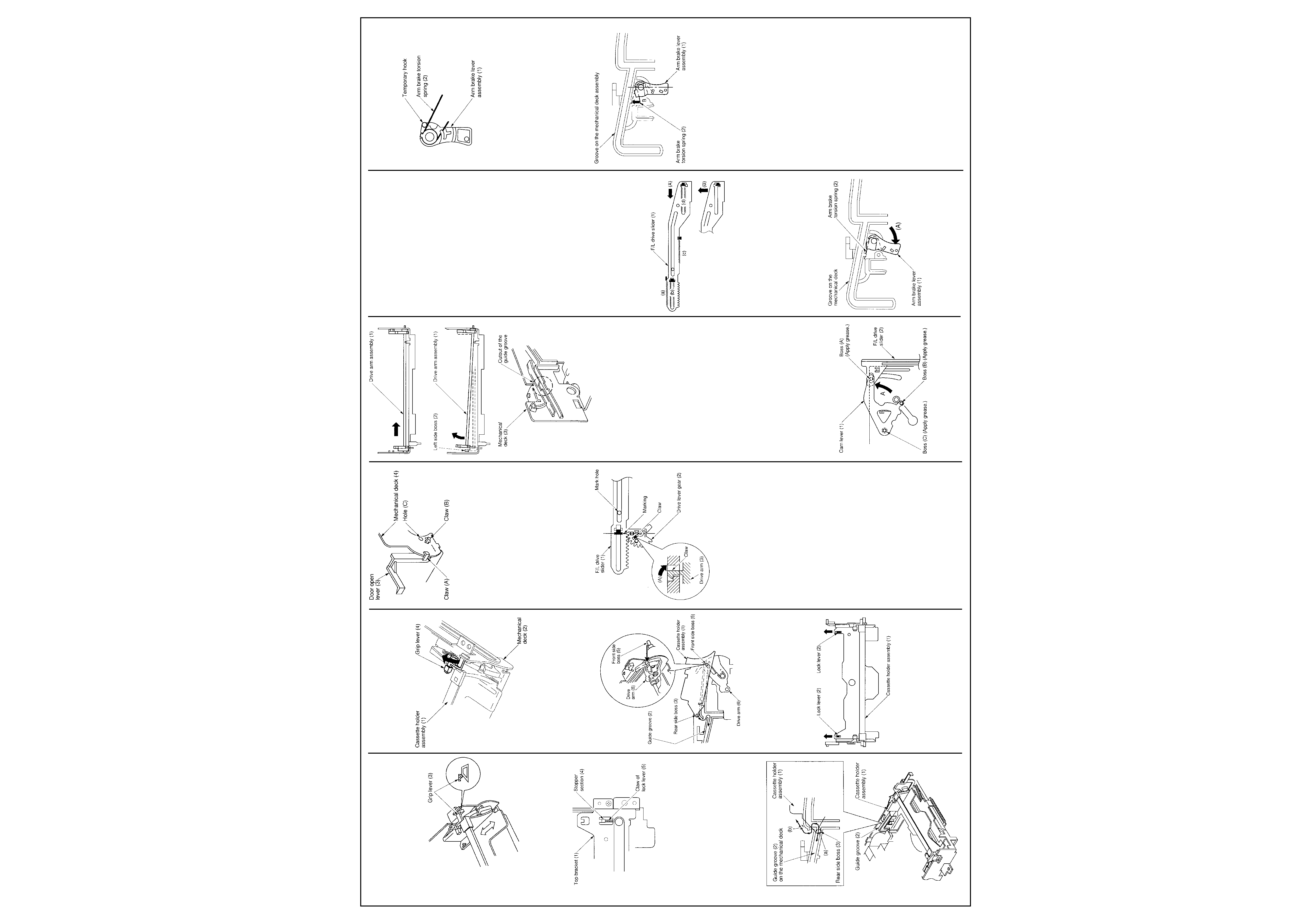
3. When mounting the top bracket (1), move the
tip of the grip lever (3) on the cassette holder
assembly to the inclined portion of a
trapezoidal cam, and then mount the top
bracket (1).
Fig. 6-1-2
Note:
· After remounting the top bracket (1), move the
cassette holder forward and backward, and
then confirm the claws of the lock lever (5)
catch completely the both left and right sides
of the stopper section (4) at the top bracket
(1)
Fig. 6-1-3
1-6-2. Cassette Holder Assembly Replace-
ment
1. Remove the top bracket. (Refer to item 1-6-1.
Top Bracket Replacement".)
2. The cassette holder assembly (1) is guided
along the guide grooves (2) with both left and
right bosses of the cassette holder assembly
(1). So first remove each side boss (3) on
both left and right sides of cassette holder
assembly (1) from the guide groove (2).
3. When the cassette holder assembly (1) is set
at the EJECT position, the boss is located at
(a), so move the boss from (a) to (b) and
remove the bosses on both left and right sides
simultaneously.
Fig. 6-2-1
Note:
The grip lever (4) on the cassette holder
assembly (1) may catch the trapezoidal cam on
the mechanical deck (2), so perform the work
lifting the grip lever in the direction
shown by the arrow.
Fig. 6-2-2
4. After removing the front side bosses (5) on
both left and right sides, remove the cassette
holder assembly (1) pulling to the front side.
5. When mounting the cassette holder assembly
(1), insert the front side bosses (5) to the U
shaped groove of the drive arm (6) and the
guide groove (2) on the mechanical deck
lifting the rear side of the cassette holder
assembly (1).
Fig. 6-2-3
6. When mounting the rear side bosses (3),
perform the reverse order of removal.
1-6-3. Door Open Lever Replacement
1. Release the lock lever (2) on the cassette
holder assembly (1) pressing in the direction
shown by the arrow.
Fig. 6-3-1
2. Move the cassette holder assembly (1)
slightly to the rear side.
3. Remove the claws (A) and (B) on the door
open lever (3) from the mechanical deck (4).
4. Match the boss on a new door open lever (3)
and the hole (C) on the mechanical deck, and
then insert the claws (B) first and then (A) to
the mechanical deck (4).
Fig. 6-3-2
5. Remount the cassette holder assembly to the
position as it was.
1-6-4. Drive Lever Gear Replacement
1. Make the cassette holder assembly to the
slot-out (EJECT) position.
Note:
· In this condition, both mark holes on the F/L
drive slider (1) and the mechanical deck fit
with each other, also the hole of the boss on
the drive lever gear (2), the center of the gear
tooth and the marking line are in line.
2. Move the claw of the drive arm (3) to the
direction of the arrow (A) and remove the
drive lever gear (2) upward.
Fig. 6-4-1
3. When remounting the drive lever gear (2),
take care of the phase position (refer to the
note described above.) and mount in the
reverse order of removal.
1-6-5. Drive Arm Assembly Replacement
1. Remove the top bracket assembly. (Refer to
item "1-6-1. Top Bracket Replacement".)
2. Remove the cassette holder assembly. (Refer
to item "1-6-2. Cassette Holder Assembly
Replacement".)
3. Remove the door open lever. (Refer to item
"1-6-3. Door Open Lever Replacement.")
4. Remove the drive lever gear. (Refer to item
"1-6-4. Drive Lever Gear Replacement".)
5. Pull the REC-inhibiting lever slightly to the
front side, turn the drive arm assembly (1) to
the front side and push it in the direction
shown by the arrow. Remove the left side
boss (2) on the drive arm assembly (1) from
the cutout of the guide groove on the
mechanical deck (3).
6. Remount the drive arm assembly (1) in the
reverse order of removal.
Fig. 6-5-1
1-6-6. Cam Lever Replacement
1. Remove the top bracket. (Refer to item "1-6-
1. Top Bracket Replacement".)
2. Remove the cassette holder assembly. (Refer
to item "1-6-2. Cassette Holder Assembly
Replacement".)
3. Remove the cam slider. (Refer to item "1-6-
41. Cam Slider Replacement".)
4. Remove the loading drive assembly. (Refer to
item "1-6-29. Loading Drive Assembly
Replacement".)
5. Remove the drive lever. (Refer to item "1-6-
40". Drive Lever Replacement".)
6. Remove the pinch roller assembly. (Refer to
item "1-6-21. Pinch Roller Assembly Replace-
ment".)
7. Remove the cam gear. (Refer to item "1-6-31.
Cam Gear Replacement".)
8. Move the cam lever (1) until it stops in the
direction shown by the arrow (A). Pull out the
cam lever (1) lifting up straightly at the
position where the cam lever (1) stops.
9. Apply grease to the portions of bosses (A) to
(C) on a new cam lever.
Note:
· Confirm that the boss (A) on the cam lever (1)
is inserted into the hole on the F/L drive slider
(2).
· After inserting the cam lever (1), confirm that
the cam lever (1) moves smoothly.
10.Replace the cam lever in the reverse order of
removal.
Fig. 6-6-1
1-6-7. F/L Drive Slider Replacement
1. Remove the top bracket. (Refer to item "1 -6-
1. Top Bracket Replacement".)
2. Remove the cassette holder assembly. (Refer
to item
1-6-2. Cassette Holder Assembly Replace-
ment".)
3. Remove the cam slider. (Refer to item "1-6-
41. Cam Slider Replacement".)
4. Remove the loading drive assembly. (Refer to
item 1-6-29. Loading Drive Assembly
Replacement".)
5. Remove the drive lever. (Refer to item "1-6-
40. Drive Lever Replacement".)
6. Remove the pinch roller assembly. (Refer to
item 1-6-21. Pinch Roller Assembly Replace-
ment".)
7. Remove the cam gear. (Refer to item "1-6-31.
Cam Gear Replacement".)
8. Remove the cam lever. (Refer to item "1-6-6.
Cam Lever Replacement".)
9. Remove the drive lever gear. (Refer to item
"1-6-4. Drive Lever Gear Replacement".)
10.Push the F/L drive slider (1) in the direction
shown by the arrow (A) and slide it. Further-
more, pull out it to the front side lifting it in the
direction shown by the arrow (B).
11.Apply grease to the shaded parts (a) to (d)
on a new F/L drive slider (1).
Note:
For the phase alignment of the drive lever gear,
refer to item "1-6-4. Drive Lever Gear Replace-
ment".
12.Replace the F/L drive slider (1) in the reverse
order of removal.
Note:
After completion of the replacement, confirm
that the F/L drive slider (1) moves smoothly.
Fig. 6-7-1
1-6-8. Arm Brake Lever Assembly and Arm
Brake Torsion Spring Replacement
1. Make the cassette holder assembly to the
slot-out (EJECT) position.
2. Turn the arm brake lever assembly (1) in the
direction shown by the arrow (A) until it stops.
Pull out the arm brake lever assembly (1) to
the front at the position it stops.
Note:
Take care that the arm brake torsion spring (2)
is removed forcefully.
Fig. 6-8-1
3. Hook the arm brake torsion spring (2)
temporarily to a new arm brake lever
assembly (1).
Note:
Take care of the direction of the arm brake
torsion spring (2) so that the longer end of the
arm brake torsion spring (2) is hooked on the
temporary hook.
Fig. 6-8-2
4. Insert the hook portion on the arm brake lever
assembly (1) to the cutout on the mechanical
deck.
5. Turn the arm brake lever assembly (1)
counterclockwise and fix it at the position
which the arm brake lever assembly (1) faces
to the straight below.
6. When pushing the tip of the arm brake torsion
spring (2) located at (B) position, the tip is
removed from the temporary hook and moves
to the hook on the mechanical (leek.
7. The arm brake lever assembly turns to the
specified position by force of the arm brake
torsion spring.
Fig. 6-8-3
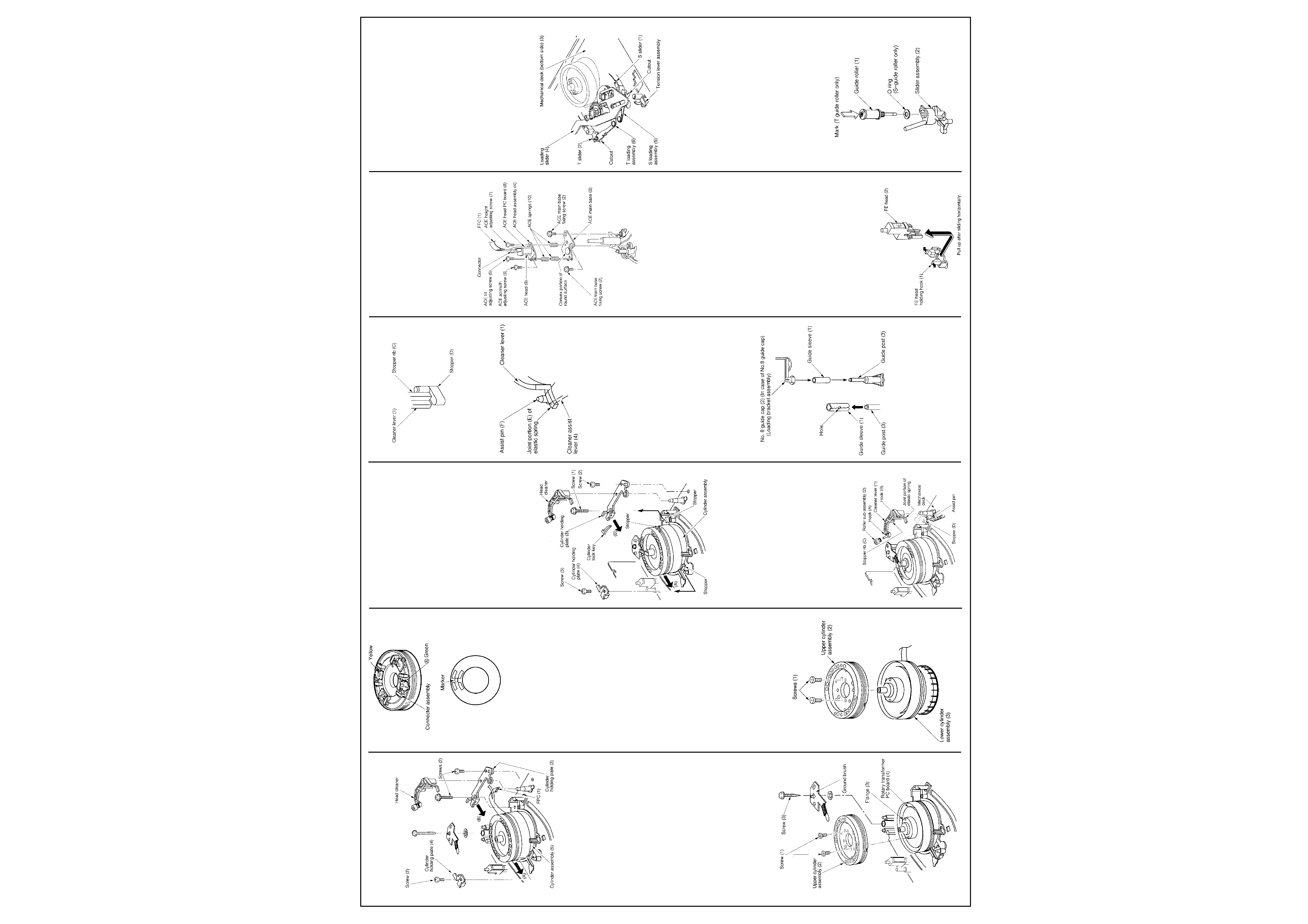
1-6-9.Cylinder Assembly Inspection and
Replacement
<Inspection>
1. Check if the tape transport surface on the
lower cylinder assembly are not damaged.
2. Check if the rotation of the upper cylinder
assembly is not abnormal. When any
abnormality is found according to the
inspection procedures described above 1 and
2, replace the cylinder assembly.
<Replacement>
1. Remove the ground brush assembly.
2. Remove the head cleaner. (Refer to item "1-
6-14. Head Cleaner Replacement.")
3. Remove the FPC (1) on the Preamplifier.
4. Remove three screws (2) and the cylinder
holding plate (3) and (4). (Refer to item "1-6-
12. Cylinder Holding Plate Replacement".)
5. Remove the cylinder assembly (5).
6. Remount the cylinder assembly (5) in the
reverse order of removal. Fix the cylinder
pressing slightly in the direction shown by the
arrow (A) and the cylinder holding plate (3)
pressing slightly in the direction shown by the
arrow (B). (Tightening torque: 294-392 mN·m
(3 - 4 kg·cm))
Continues Next Page ...
4
TOSHIBA V 856 B
www.u-view.co.uk
Mechanical Adjustments
Cont'd
Fig. 6-9-1
Note:
· When replacing, take much care not to touch
the video head directly and damage the
cylinder.
7. Perform the tape transport adjustment.
1-6-10. Upper Cylinder Assembly Inspection
and Replacement
<Inspection>
1. Check if the video heads are damaged or
worn out.
2. Check the video heads for clogging. (In case
that the clogging is not remedied after
cleaning.)
<Replacement>
1. Remove the ground brush assembly.
2. Remove two securing screws (1) and remove
the upper cylinder assembly (2).
3. Clean the new upper cylinder assembly (2)
and the flange (3) mounting surface with a
cleaning kit.
4. Align the head A (green) and the marker on
the rotary transformer PC board (4) and then
mount the upper cylinder assembly (Tighten-
ing torque : 294 - 392 mN·m. (3 - 4kg·cm)
Fig. 6-10-1
Fig. 6-10-2
Fig. 6-10-3
Note:
· During the work in steps 3 to 4, take care not
to touch the connector assembly and deform
the spring.
5. Perform the tape transport adjustment
according to its procedures.
1-6-11. Lower Cylinder Assembly Inspection
and Replacement
<Inspection>
1. Check if the tape transport surface on the
lower cylinder assembly is not damaged.
2. Check if the rotation of the upper cylinder
assembly is not abnormal.
3. Check if the FPC on the Preamplifier is not
damaged. When any abnormality is found
under the inspection described in the steps
(1) to (3), replace the cylinder assembly.
<Replacement>
1. Remove the cylinder assembly. (Refer to item
"1-6-9. Cylinder Assembly Inspection and
Replacement".)
2. Remove two securing screws (1) and remove
the upper cylinder assembly (2).
3. Replace the lower cylinder assembly (3).
4. Mount the lower cylinder assembly in the
reverse order of removal taking care not to
touch the video head directly and damage the
cylinder.
Note:
· Take care not to deform the joint spring on the
upper cylinder assembly (2).
5. Perform the tape transport adjustment
according to its procedures.
Fig. 6-11-1
1-6-12. Cylinder Holding Plate Replacement
1. Remove screws (1) and (2) securing the
cylinder holding plate (3) and a screw (5)
securing the cylinder holding plate (4).
2. Remove the cylinder holding plate (3) and (4)
sliding in the direction shown by the arrow (B)
and (A).
3. Eliminate the cylinder lock key (wedge
shaped parts).
4. After replacing the cylinder holding plates (3)
and (4), mount new parts in the reverse order
of removal.
Note:
· When remounting, fix the cylinder while
pushing in the direction shown by the arrow
(A) and the cylinder holding plate (3) in the
direction shown by the arrow (B). Then tighten
three screws while pushing the cylinder
holding plate (4) toward the stopper on the
outsert of the mechanical deck.
· Tightening order of the screws is (1) > (2) >
(5).
· Tightening torque of the screws (1), (2), (5) is
294 - 392 mN·m (3 - 4 kg·cm).
Fig. 6-12-1
1-6-14. Head Cleaner Replacement
<Roller sub assembly replacement>
1. Remove the roller sub cleaner assembly (2)
pulling upward from the hook (A) on the
cleaner lever (1).
2. After replacing the roller sub assembly, mount
in the reverse order of removal.
<Cleaner lever replacement>
1. Undo the hook (B) of the cleaner lever (1)
from the mechanical deck, and pull out the
cleaner lever (1) upward.
2. Replace the cleaner lever (1) on the roller sub
assembly (2), and mount the cleaner lever (1)
in the reverse order of removal.
Note:
· Take care the roller sub assembly (2) is not
stained with grease or oil.
Fig. 6-14-1
Note:
· When remounting the head cleaner, position
the stopper rib (C) in front of the stopper (D).
Fig. 6-14-2
Note:
· Confirm that the joint portion (E) of the elastic
spring positions in front of the assist pin (F)
on the cleaner assist lever (4).
Fig. 6-14-3
1-6-15. No. 8, No. 3 Guide Sleeves Replace-
ment
1. When replacing the No. 8 guide sleeve (1),
first remove the guide cap (2) on the loading
bracket assembly.
2. Pull out the guide sleeve (1) from the guide
post (3).
Note:
· Take care not to break the No. 8, No. 3 guide
posts on the mechanical deck if twisting the
guide sleeve forcefully.
3. Insert a new guide sleeve (1) to the guide
post.
Note:
· When inserting the guide sleeve (1), take care
so that its hole faces the opposite side to the
tape transport surface.
4. For No. 8 guide sleeve, insert the No. 8 guide
cap (2) onto it.
Fig. 6-15-1
1-6-16. ACE Head Assembly Replacement.
1. Remove the FFC (1) from the connector.
2. Remove two screws (2) and remove the ACE
main base (3) and ACE head assembly (4).
3. Remove three adjusting screws (5), (6), and
(7) and then remove the ACE head assembly
(4).
Note:
· When replacing ACE head (9) only without
replacing its PC board, unsolder the ACE
head (9) on the ACE head PC board (8) and
then remove the ACE head (9) and the ACE
head PC board (8).
4. Mount the ACE head assembly (4) in the
reverse order of removal.
Note:
· When reassembling the ACE head assembly
(4), First set the ACE springs (10) between
the ACE head assembly (4) and the ACE
main base (3), and secure the adjusting
screws (5), (6), and (7).
Fig. 6-16-1
· When securing three adjusting screws, mount
the ACE main base (3) and ACE head
assembly (4) so that the clearance between
them becomes parallel with the specified
preset value (4.3
± 0. 1 mm).
5. After replacing, perform the tape transport
adjustment.
Note:
· When replacing the ACE head assembly (4),
always use an ACE head (9) having the same
part number. Do not use any other ACE head
assembly.
1-6-17. FE Head Replacement
1. Open the FE head holding hook (1) on the
mechanical deck slightly in both left and right
directions and remove the FE head (2) by
moving in the direction shown by the arrows.
2. Replace the FE head (2) and mount the parts
in the reverse order of removal.
3. Perform adjustment from the linearity
adjustment item in the tape transport system
adjustment.
Note:
· When mounting the FE head, Push the head
backward completely.
· Though FE head (2) can be removed upward
by opening the FE head holding hook (1) to
both left and right directions, perform the
standard replacement procedure described
above since this may cause deformation of
the hook.
Fig. 6-17-1
1-6-18. S, T Slider Replacement
1. Remove the tension lever assembly. (Refer to
item. "1-6-23. Tension Lever Assembly
Replacement".)
2. Remove the loading slider. (Refer to item "1-
6-25. Loading Slider Replacement".)
3. Remove the S loading assembly. (Refer to
item "1-6-24. S Loading Assembly Replace-
ment".)
4. Remove the T loading assembly. (Refer to
item "1-6-24. T Loading Assembly Replace-
ment".)
5. Remove the S slider (1) and T slider (2) lifting
up to the cutout of the groove on the mechani-
cal deck (3).
6. Remove the S and T guide rollers and mount
a new slider.
7. Mount the parts in the reverse order of
removal.
Note:
Perform the phase alignment between the
loading slider (4) and S, T loading assemblies
(5), (6) referring each replacement procedure.
Fig. 6-18-1
8. After completion of the replacement, perform
the adjustment from item I in the tape
transport system adjustment.
1-6-19. S, T Guide Rollers Replacement
The same replacement procedures will be
applied for the S, T guide rollers.
1. Turn the guide roller (1) counterclockwise and
remove the guide roller (1) from the slider
assembly (2).
2. Mount a new guide roller on the slider
assembly (2) turning clockwise.
3. After completion of the replacement, perform
the adjustment from the linearity adjustment
in the tape transport system adjustment..
Note:
· O ring is not applied to the T guide roller.
· For the T guide roller, marking is located on
the upper flange. So take care not to mis-
mount with the S guide roller.
Fig. 6-19-1
5
TOSHIBA V 856 B
U-View Limited
Mechanical Adjustments
Cont'd
1-6-20. S, T Impedance Roller Replacement
1. Remove two screws (1) and (2), and then
remove two brackets (3), (4).
2. Replace two impedance rollers (5), (6).
3. Mount the parts in the reverse order of
removal.
4. After completion of the replacement, perform
the adjustment from the linearity adjustment
in the tape transport system adjustment.
Note:
· S, T impedance rollers (5), (6) is not always
applied to all models.
Fig. 6-20-1
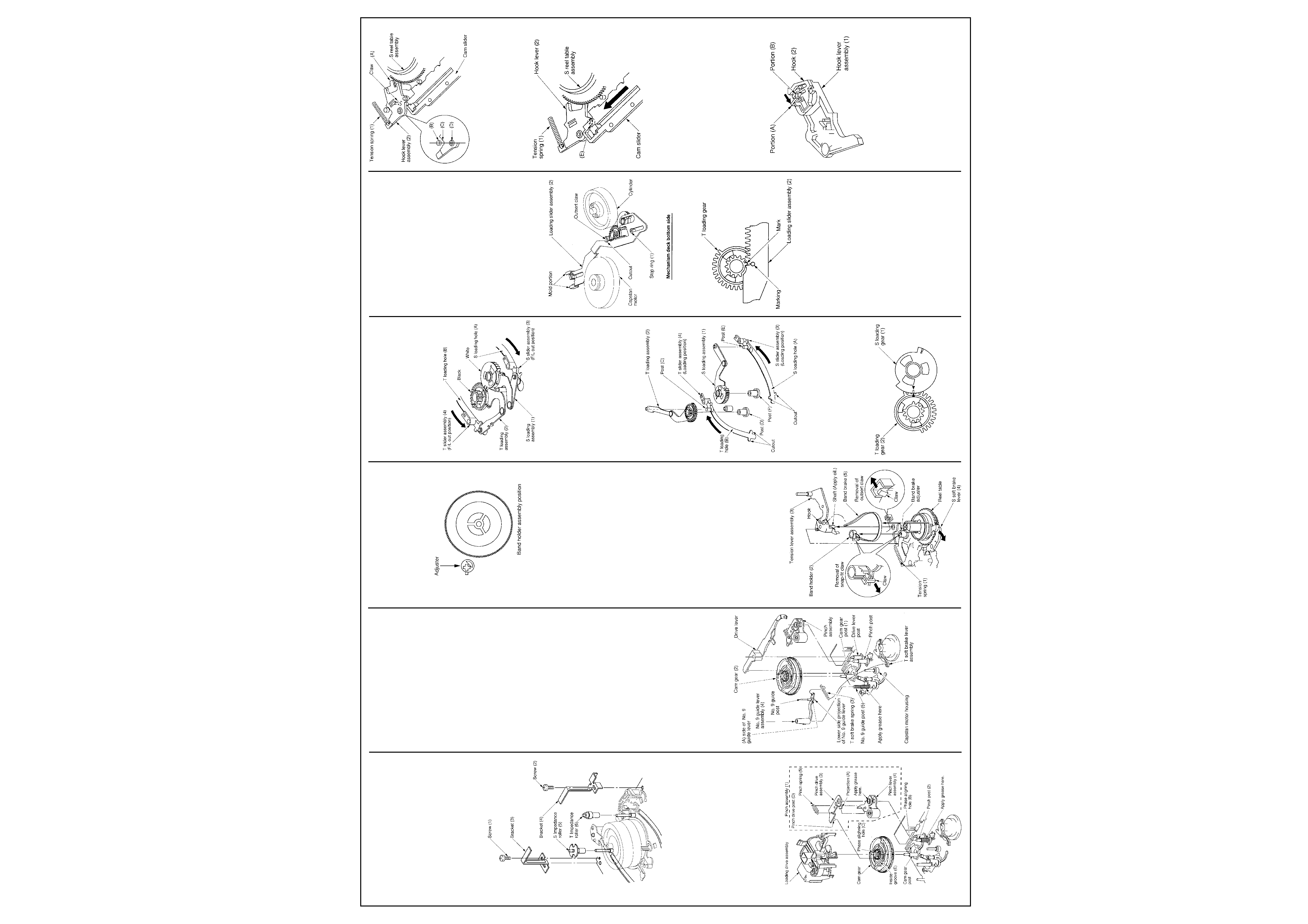
1-6-21. Pinch Roller Assembly Replacement
1. Remove the loading drive assembly (Refer to
item "1-6-29. Loading Drive Assembly
Replacement".)
2. Remove the pinch assembly (1) lifting
vertically from the pinch post (2).
3. Remove the pinch spring (5) from the hooks
on the pinch drive assembly (3) and the pinch
lever assembly (4).
4. Turn the projection (A) on the pinch drive
assembly (3) counterclockwise till it goes to
the cutout on the pinch lever assembly (4).
5. After replacing, mount the parts in the reverse
order of removal.
6. After completion of the replacement, perform
the tape transport adjustment.
Fig. 6-21-1
Note:
· For the removal and assembling of the loading
drive assembly, refer to item 1-6-29.
· When inserting the pinch assembly (1) into the
pinch post (2), insert it so that the pinch drive
post (D) enters the groove (E) inside the cam
gear.
· Take care not to touch the surface of the pinch
roller and the grease is not stained on it.
· Be sure to apply grease to the surface of the
bar-ring on the pinch lever assembly (4) and
the pinch post (2) on the mechanical deck.
1-6-22. No. 9 Guide Lever Assembly Replace-
ment
1. Remove the loading drive assembly. (Refer to
item "1-6-29. Loading Drive Assembly
Replacement".)
2. Remove the drive lever. (Refer to item "1-6-
40. Drive Lever Replacement".)
3. Remove the pinch assembly. (Refer to item
"1-6-21. Pinch Roller Assembly Replace-
ment".)
4. Remove the ACE head assembly. (Refer to
item "1-6-16. ACE Head Assembly Replace-
ment".)
5. Remove the cam gear (2) from the cam gear
post (1).
6. Remove the T soft brake spring (3).
7. Remove the No. 9 guide lever assembly (4)
lifting the No. 9 guide lever assembly upward
from the No. 9 guide post (5).
8. After replacing, mount the parts in the reverse
order of removal.
9. After completion of the replacement, perform
the tape transport adjustment.
Note:
· When mounting the No. 9 guide lever
assembly (4), confirm that (A) side of the No.
9 guide lever assembly (4) touches the
capstan motor housing portion.
· After inserting the No. 9 guide lever assembly
(4) into the No. 9 guide post (5). confirm that
the lower projection of the No. 9 guide lever
assembly (4) touches to the upper surface of
the mechanical deck.
· Take care that the grease is not stained on the
No. 9 guide post of the No. 9 guide lever
assembly (4).
· Be sure to apply grease to the No. 9 guide
post (5).
Fig. 6-22-1
1-6-23. Tension Lever Assembly, Band Holder
and Band Brake Replacement
1. Remove the tension spring (1).
Note:
· Take care not to extend or deform the tension
spring.
2. After setting the band brake adjuster to the
band holder assembling position, undo the
claw of the snap-fit type and remove the band
holder from the band brake adjuster by lifting
it upward.
Fig. 6-23-1
Detail of band holder assembling
3. Undo the claw of the outsert on the mechani-
cal deck catching the shaft of the tension lever
assembly (3) and remove the tension lever
assembly lifting it upward.
4. Remove the band brake (5) from the reel
table while pulling the S soft brake lever (4) in
the direction shown by the arrow.
5. Remove the band brake (5) from the hook on
the tension lever assembly (3).
Note:
· Take care not to contaminate, bend or damage
the felt surface on the band brake (5).
6. After replacing the tension lever assembly (3),
clean the shaft on the tension lever and apply
a small amount of oil.
7. Mount the parts in the reverse order of the
removal.
8. After mounting, check the tension post
position and perform the adjustment and back
tension check.
9. After completion of the replacement, perform
the adjustment from the linearity adjustment in
the tape transport system adjustment.
Note:
· The band holder (2) can be replaced in the
procedures described above steps 1 to 3.
· The band brake (5) can be replaced in the
procedures described above steps 1 to 5.
· When replacing the band holder (2) and band
brake (5), the linearity adjustment is not
necessary.
Fig. 6-23-2
1-6-24. S,T Loading Assembly Replacement
1. Remove the mechanical deck assembly from
the main PC board.
2. Set the mechanical position to the F/L out
position (front side). Turn over the mechanical
deck.
3. Remove the loading slider assembly. (Refer to
item "1-6-25. Loading Slider Assembly
Replacement".)
Fig. 6-24-1
4. Remove the S, T loading assemblies (1), (2).
5. Insert the S, T slider assemblies (3), (4) along
the cutout of the S, T loading holes (A) and
(B) on the mechanical deck and set the S, T
slider assemblies (3), (4) to the loading
position (rear side).
6. Insert the T loading assembly (2) to the post
(C) on the T slider assembly (4) and the post
(D) on the mechanical deck. And insert the S
loading assembly (1) to the post (E) on the S
slider assembly (3) and the post (F) on the
mechanical deck.
Fig. 6-24-2
Note:
· Align the phases of the s marks on the S, T
loading gear (1), (2).
7. Set the S, T slider assemblies (3), (4) to the F/
L out position.
Fig. 6-24-3
1-6-25. Loading Slider Assembly Replace-
ment
1. Remove the mechanical deck from the main
PC board.
2. Set the mechanical position to the F/L out
position.
3. Turn over the mechanical deck.
4. Remove the stop ring (1).
5. Remove the loading slider assembly (2) while
lifting its tip upward using the mold portion on
the loading slider assembly (2) as a fulcrum.
6. Mount the parts in the reverse order of
removal.
Note:
· When mounting the loading slider assembly
(2), insert the tip of the loading slider assem-
bly (2) slightly to the mold portion, then mount
it so that the claw on the outsert is in the
position of the cutout portion of the loading
slider assembly.
· Confirm that the position mark on the loading
slider assembly (2) and the mark on the T
loading gear match each other in position.
Fig. 6-25-1
View from Mechanical deck bottom side
Fig. 6-25-2
1-6-26. Hook Lever Assembly Replacement
1. Remove the top bracket. (Refer to item "1-6-
1. Top Bracket Replacement".)
2. Remove the cassette holder assembly. (Refer
to item "1-6-2. Cassette Holder Replace-
ment".)
3. Remove the drive arm assembly. (Refer to
item "1-6-5. Drive Arm Assembly Replace-
ment".)
4. Remove the tension spring (1).
5. Turn the hook lever assembly (2)
counterclockwise slightly, and remove the
claw on the hook lever assembly (2) then
replace.
6. After replacing the hook lever assembly (2) ,
insert the (A) portion of the hook lever under
the S reel table assembly. When the portions
(B), (C), (D) are in line, push the claw into the
mechanical deck.
Fig. 6-26-1
7. Turn the hook lever assembly (2) clockwise till
it stops, and mount the tension spring (1).
After replacing the hook lever assembly (2),
slide the cam slider in the direction shown by
the arrow, and then position the boss (E)
under the cam slider.
Fig. 6-26-2
1-6-27. Hook Replacement
1. Remove the hook lever assembly. (Refer to
item "1-6-26. Hook Lever Assembly Replace-
ment".)
2. Turn over the hook lever assembly (1) and
remove the hook lever assembly (1) opening
the portion (A) of the hook (2) slightly and
lifting the hook (2) upward.
3. When mounting a new hook, push the hook
(2) in the portion (B) from above.
Note:
· Take care not to confuse the mounting
direction of the hook (2).
Fig. 6-27-1
1-6-28. Tension Drive Lever Replacement
1. Remove the cam slider. (Refer to item "1-6-
41. Cam Slider Replacement".)
2. Turn over the mechanical deck and remove
the tension drive lever (1) from the projection
(A) moving counterclockwise slightly.
3. After replacing the tension drive lever (1),
mount in the reverse order of removal.