3LCD DATA PROJECTOR
SERVICE MANUAL
TLP710U, TLP711U
TLP710E, TLP711E
TLP710H, TLP711H
FILE NO. 333-9807
PRINTED IN JAPAN, Nov., 1998 S
TLP711

SECTION 1
PART REPLACEMENT AND ADJUSTMENT PROCEDURES
SECTION 2
SERVICING DIAGRAMS
SECTION 3
PARTS LIST
1 . SAFETY PRECAUTION ...................................................... 3 - 1
2 . NOTICE ..................................................................................... 3 - 1
3 . ABBREVIATIONS .................................................................. 3 - 1
3-1. Integrated Circuit (IC) .................................................... 3-1
3-2. Capacitor (Cap) ................................................................ 3-1
3-3. Resistor (Res) ..................................................................... 3-1
4 . ELECTRICAL ADJUSTMENT .......................................... 1 - 6
4-1. LCD Drive Adjustment (A) ....................................... 1 - 8
4-1B. LCD Drive Adjustment (B) ................................. 1-10
4-2. Camera Section Adjustment (For TLP711) .............. 1-14
1 . PART CONFIGURATION AND THEIR SYMBOLS 2 - 1
2 . PRINTED WIRING BOARD AND
SCHEMATIC DIAGRAM .................................................... 2 - 7
3 . BLOCK DIAGRAM ............................................................... 2 - 7
3-1. Video Block Diagram ....................................................... 2-7
4 . CIRCUIT DIAGRAMS ......................................................... 2 - 9
4-1. Power Circuit Diagram .............................................. 2 - 9
4-2. Drive Circuit Diagram ................................................... 2-13
4-3. Digital 1 Circuit Diagram ............................................. 2-17
4-4. Digital 2 Circuit Diagram ............................................. 2-20
4-5. Digital 3 Circuit Diagram ............................................. 2-23
4-6. RGB Circuit Diagram .................................................... 2-26
4-7. Input Circuit Diagram ................................................... 2-29
4-8. Shading Circuit Diagram .............................................. 2-31
4-9. Up-Con Circuit Diagram .............................................. 2-33
4-10. ............................................. Camera Out Circuit Diagram
2-37
4-11. .................................................. FAN-Key Circuit Diagram
2-41
1 . LOCATION OF MAIN PARTS ......................................... 1 - 1
2 . LOCATION OF PC BOARDS ........................................... 1 - 1
3 . DISASSEMBLING .................................................................. 1 - 2
3-1. Main Unit Optical Box ................................................. 1-2
CONTENTS
SAFETY PRECAUTIONS .............................................................. i
IMPORTANT PRECAUTIONS .................................................... i
IMPORTANT SAFETY INSTRUCTIONS ............................... i i
4 . EXPLODED VIEWS .............................................................. 3 - 2
4-1. Packing Assembly ............................................................. 3-2
4-2. Chassis Assembly (1) ........................................................ 3-3
4-3. Chassis Assembly (2) (For TLP711) .............................. 3-4
4-4. Optical Box Assembly ...................................................... 3-5
4-5. Arm Assembly (For TLP711) ......................................... 3-6
5 . PARTS LIST ............................................................................. 3 - 7
1-1
SECTION 1
PART REPLACEMENT AND
ADJUSTMENT PROCEDURES
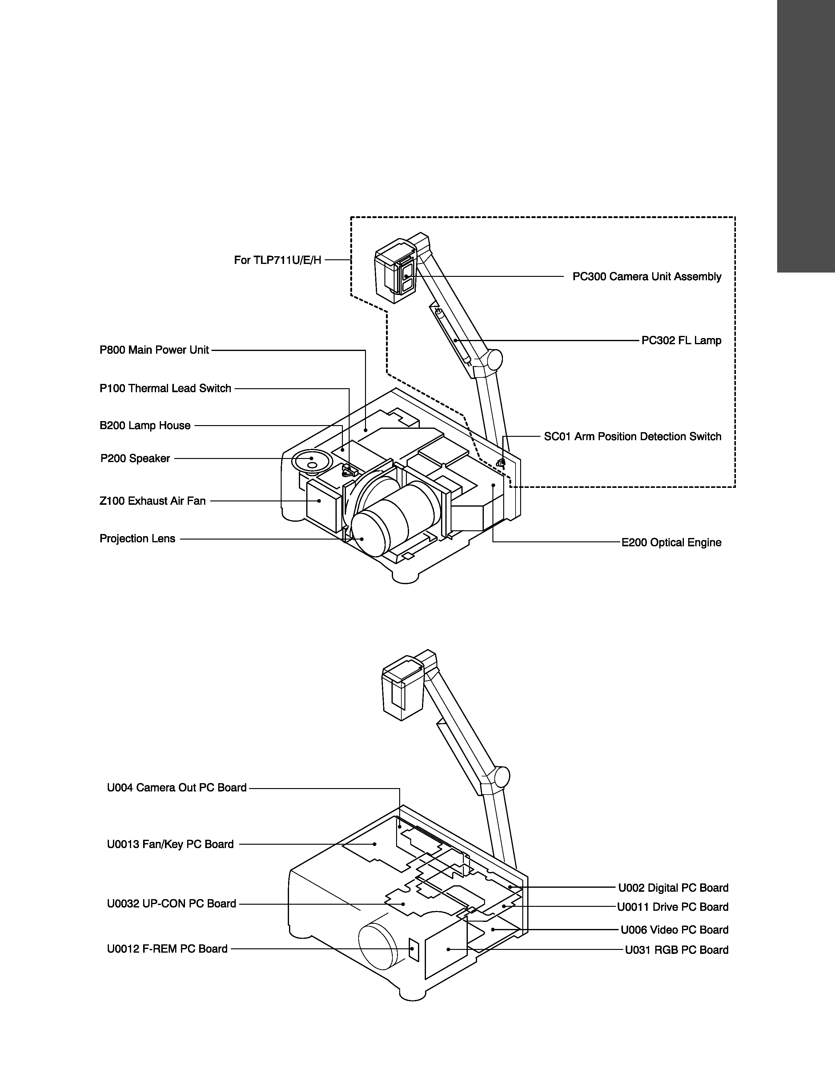
1. LOCATION OF MAIN PARTS
Fig. 1-1-1
2. LOCATION OF PC BOARDS
Fig. 1-2-1
SECTION
1
P
A
R
T
REPLA
CEMENT
AND
ADJUSTMENT
PROCEDURES
1-2
CAUTIONS BEFORE STARTING SERVICING
Electronic parts are susceptible to static electricity and may easily damaged, so do not forget to take a proper
grounding treatment as required.
Many screws are used inside the unit. To prevent missing, dropping, etc. of the screws, always use a magnetized
screwdriver in servicing. Several kinds of screws are used and some of them need special cautions. That is, take care
of the tapping screws securing molded parts and fine pitch screws used to secure metal parts. If they are used
improperly, the screw holes will be easily damaged and the parts can not be fixed.
3. DISASSEMBLING
3-1. Main Unit Optical Box
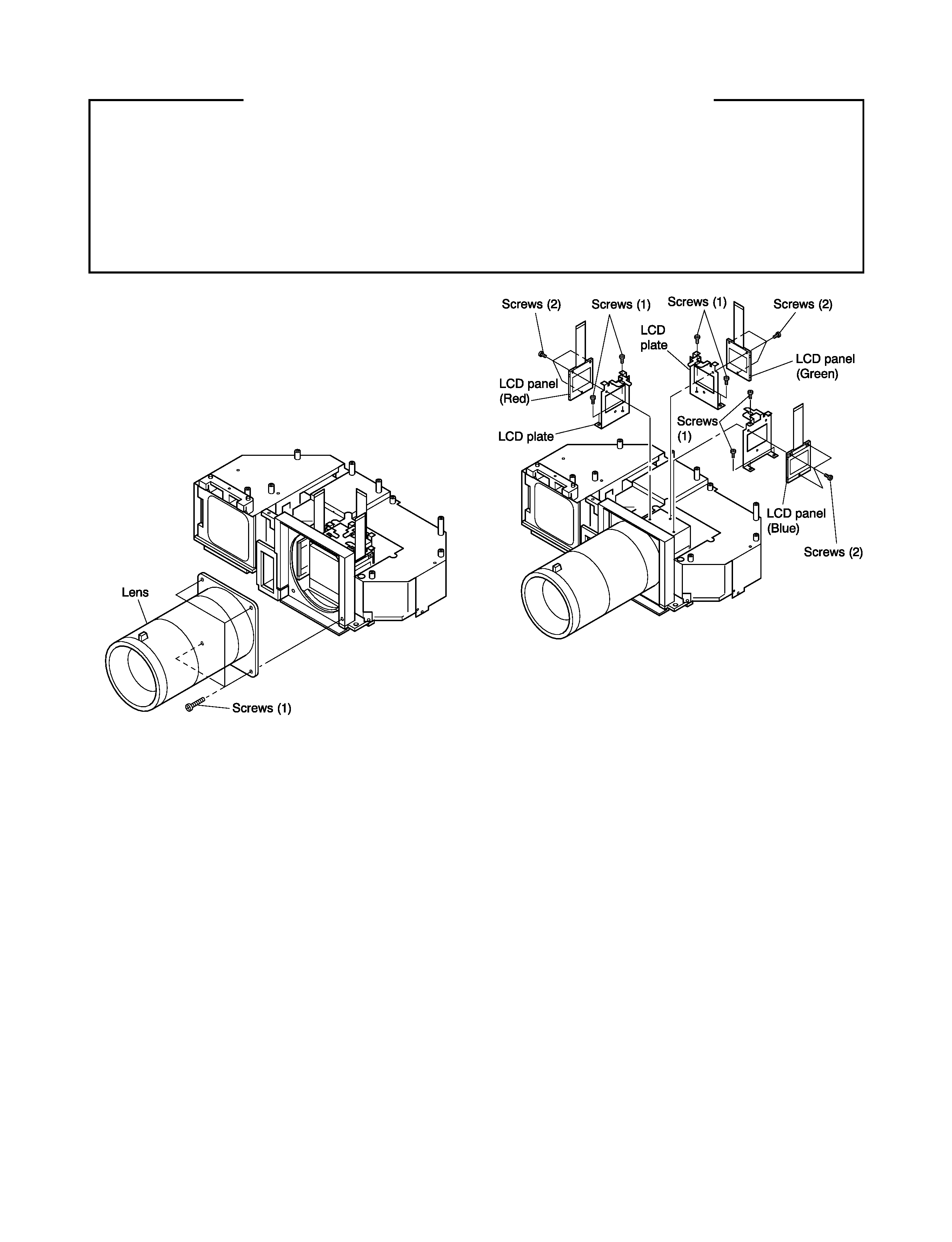
3-1-1. Lens
1. Remove optical box.
2. Remove 4 screws (1) and remove lens.
Fig. 1-3-1
3-1-2. LCD Block, LCD Plate and LCD Panel
Note:
· Do not touch the LCD panels with your bare fingers.
Wear white cotton gloves when working with the
panels.
1. Remove all cables connected to connectors on PC
board and LCD panel and drive PC board.
2. Remove FPC section of LCD panel from drive PC
board.
3. Remove 3 screws (1) (always use a screw driver with a
strong magnet) and remove LCD plate with LCD to be
replaced from LCD block. When replacing three
LCDs at the same time, first remove green LCD plate
from the LCD block.
4. Remove 3 screws (2) and remove LCD panel from
LCD plate.
Fig. 1-3-2
< How to mount a new LCD >
1. When mounting a red LCD, mount it on the red LCD
plate (No. 23430555) or when mounting a blue LCD,
mount it on the blue LCD plate (No.23430554) so
that the FPC section faces upward and main unit side
faces downward.
2. When mounting a green LCD, mount it on the LCD
plate used so far. Then place the green LCD on it in
the same direction as the red and blue LCDs by
tightening screws (3 holes on the LCD plate).
3. Mount the LCD plate with a new LCD mounted at the
bottom side of the LCD block (can be mounted only
in one direction) and tighten the screws. Do not
tighten the screws completely. Tighten the screws
temporarily so that the LCD can move for later pixel
matching adjustment of the LCDs.
1-3
< Drive PC board remounting >
Connect cables removed from connectors on the drive PC
board and the LCD panel as they were connected. (If a
signal generator which can not generate a white raster
signal is not available, do not connect the LCD panel.)
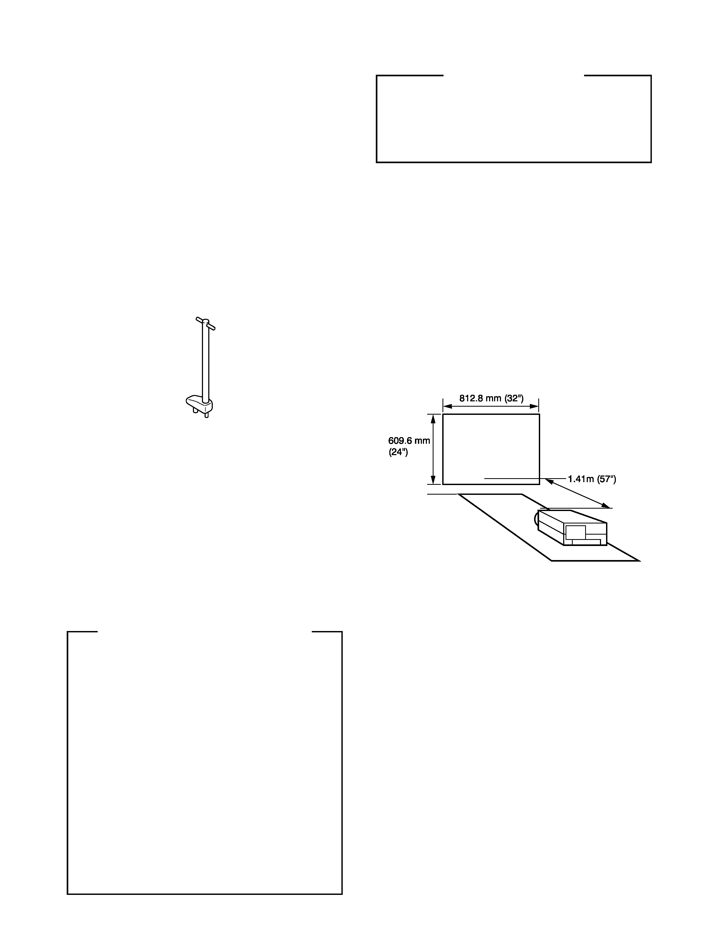
< Setup >
1. Make a wall chart on white fiber board as illustrated
in Fig. 1-3-4.
Note:
· Only use a stiff material to prevent focus errors.
Fig. 1-3-4
2. Retract the foot adjusters so the unit sits flat.
3. Place the LCD Projector on a table so that the front
edge of the lens is 1.41m from the wall. (Refer to Fig.
1-3-4.)
4. Set the zoom ring to the maximum wide setting.
5. Adjust the focus ring to the center of its range.
6. Feed a white raster signal through RGB connectors
and turn on the power of the projector. (If a signal
generator which provides a white raster signal is not
available, turn on the power without connecting the
LCD panel.)
7. If all three LCD panels need to be replaced, refer to
the "Green LCD adjustment".
< Adjustment of LCD >
If the red and blue LCD panels need to be adjusted,
follow the procedures in the item "Red/Blue LCD
adjustment". However, if the green LCD panel needs to
be adjusted, follow the procedures in the item "Green LCD
adjustment". After the green LCD panel adjustment is
carried out, it is necessary to replace or adjust the red and
blue LCD panels as described in the item "Red/Blue LCD
adjustment".
< Service jig >
· Extension cable kit : 23588458
· Focus adjust jig : 23430581
Fig. 1-3-3
When using the extension cable kit (23588458), you will
perform the adjustment on PC boards removing the PC
boards from the unit.
1. Remove the PC boards (Video, digital and drive) from
the unit.
2. Connect PC boards each other again.
3. Connect the unit and PC boards removed using the
extension cable.
Connection of each extension cable
Connection of each extension cable
Connection of each extension cable
Connection of each extension cable
Connection of each extension cable
(1) Power unit Fan/Key board (PF004)
26P
(Part code: 23588463)
(2) UP-CON board Camera out (PV003)
26P
(3) Intake fan Fan/Key board (PF011)
5P
(Part code: 23588460)
(4) Exhaust fan Fan/Key board (PF012)
3P
(Part code: 23588459)
(5) Thermal lead SW Fan/Key board (PF003) 2P
(Part code: 23588465)
(6) LCD panel Drive board (P401)
32P
(Part code: 23588464)
(7) LCD panel Drive board (P501)
32P
(Part code: 23588464)
(8) LCD panel Drive board (P601)
32P
(Part code: 23588464)
This connector is open
This connector is open
This connector is open
This connector is open
This connector is open
(1) PL001
Fan/Key board
PL005
(2) PL002
Digital board F. REM board
(3) PF006
Digital board F. REM board