
SERVICE MANUAL
FILE NO. 330-200103
SUPPLEMENT
3LCD DATA PROJECTOR
TLP-250/251/250C/251C
TLP-550/551/550C/551C
SECTION 1
PART REPLACEMENT AND
ADJUSTMENT PROCEDURES
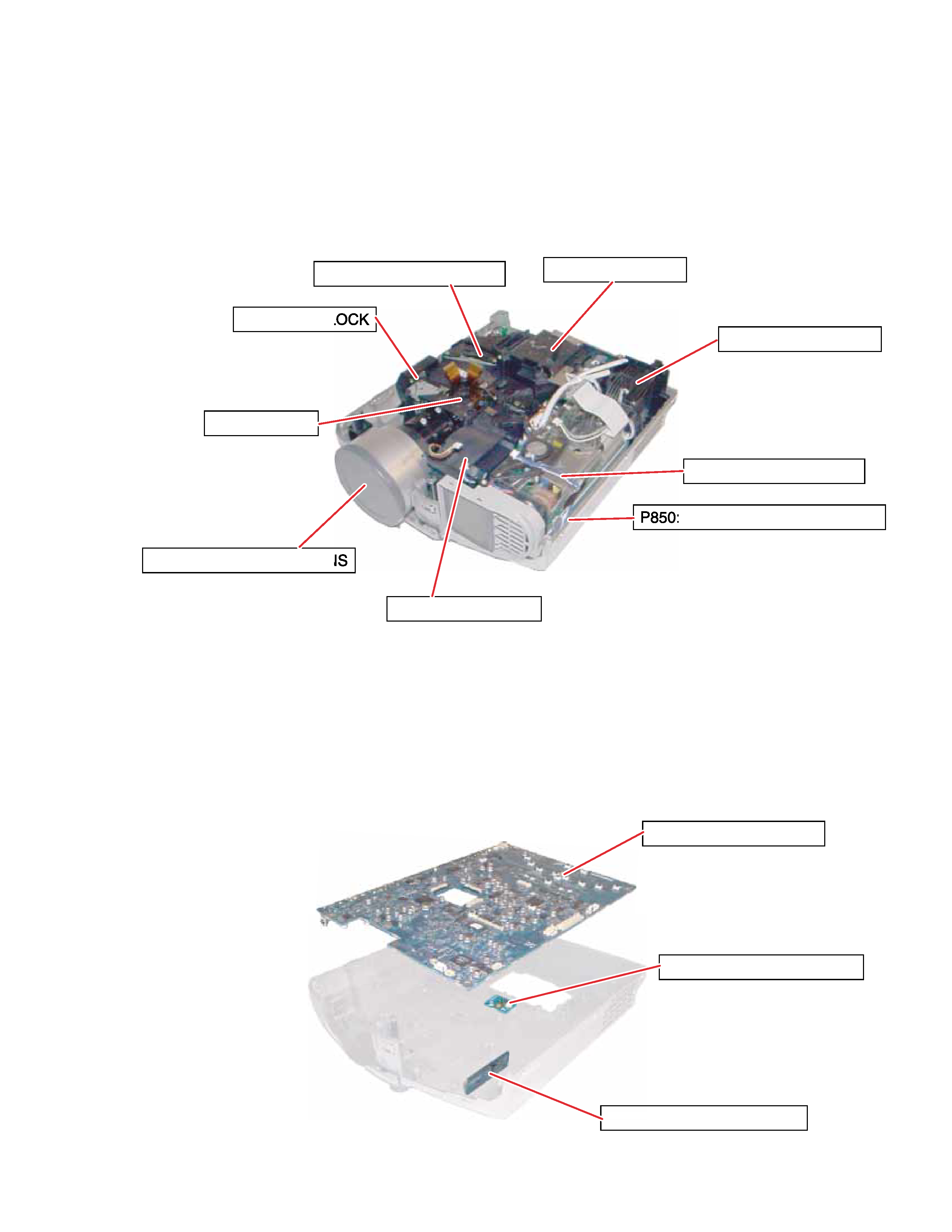
1. LOCATION OF MAIN PARTS
LCD BLOCK
Z100: INTAKE FAN
P800: POWER SUPPLY
E200: OPTICAL ENGINE
E201A: PROJECTION LEN
LAMP HOUSING
SPEAKER BL
Z101: EXHAUST FAN
: BALLAST POWER SUPPLY
2. LOCATION OF PC BOARD
U001: MAIN PC BOARD
U002: SENSOR PC BOARD
U002:
1-1
U003: SWITCH PC BOARD
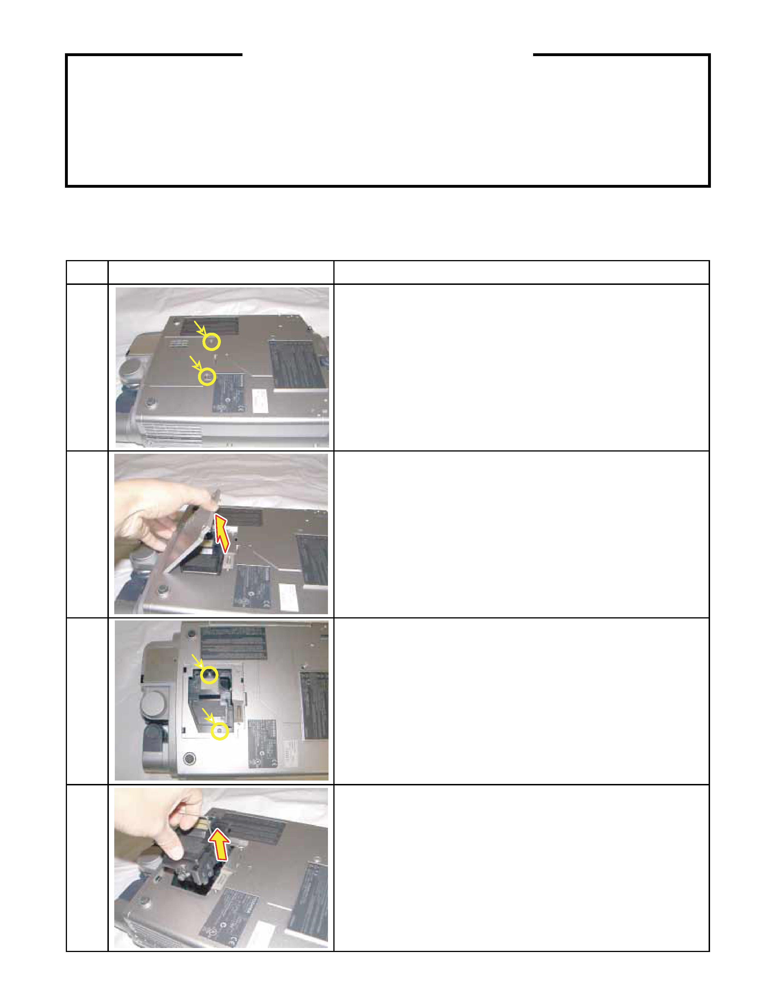
3. REPLACEMENT OF MECHANICAL PARTS
3-1. Lamp Assembly
1-2
CAUTIONS BEFORE SERVICING
Electronic parts are susceptible to static electricity and may easily be damaged, so do not forget to take
proper grounding treatment as required.
Many screws are used inside the unit. To prevent missing, dropping, etc. of the screws, always use a
magnetized screwdriver in servicing. Several kinds of screws are used and some of them need special
cautions. That is, take care of the tapping screws securing molded parts and fine pitch screws used to
secure metal parts. If they are used improperly, the screw holes will be easily damaged and the parts can
not be fixed.
Step
Figure
Explanation
1
2
3
4
Loosen 2 screws (M3 x 8).
These screws are retained with split washers.
Remove the lamp cover.
Loosen 2 screws that secure the lamp module (M3 x 8).
These screws are retained with split washers.
Lift the lamp module and slide out from the projector.
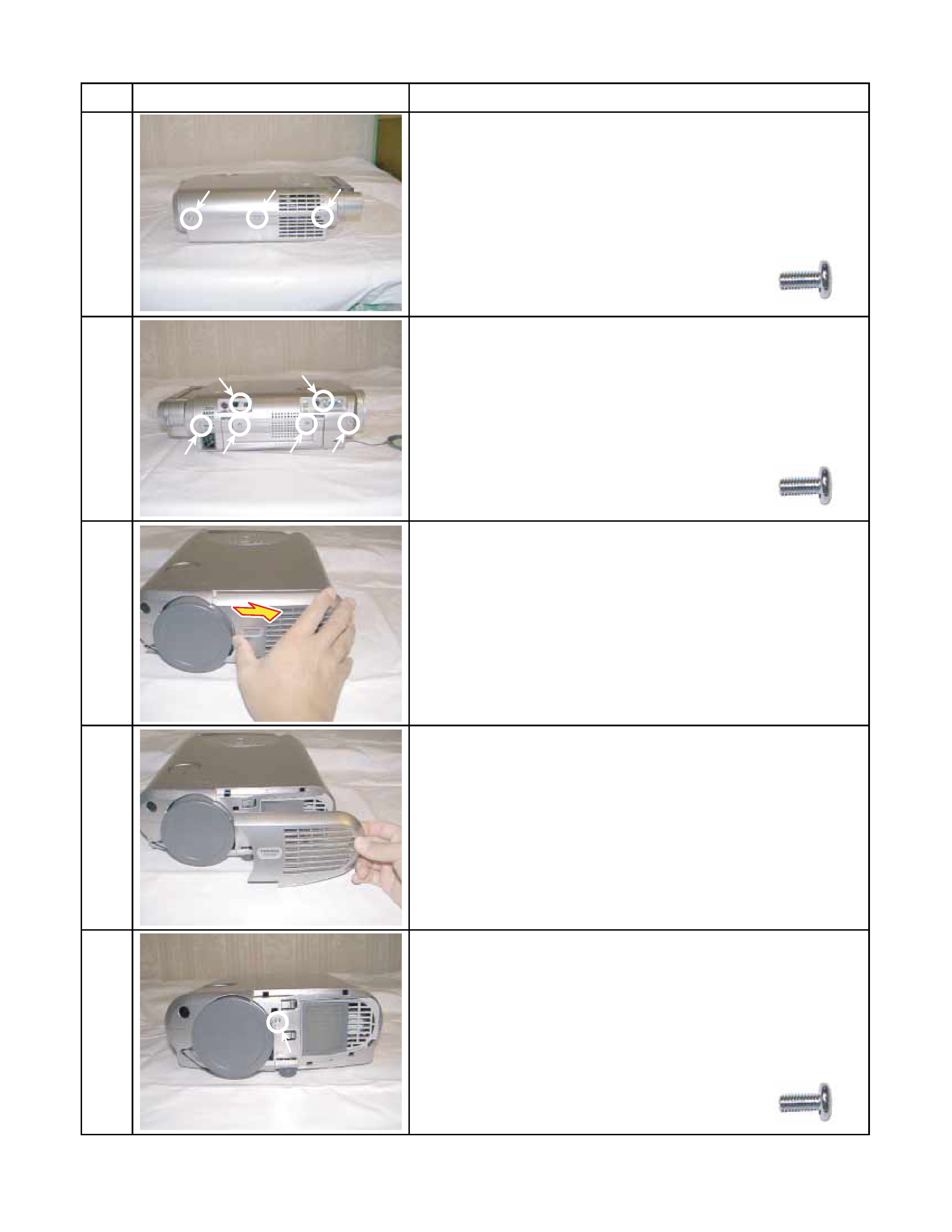
3-2. Top Cover
1-3
Step
Figure
Explanation
1
2
3
4
5
[Left Side]
Remove 3 screws (M3 x 6).
[Right Side]
Remove 6 screws (M3 x 6).
[Front]
Remove front cover.
Screw : type [M-1]
Screw : type [M-1]
Remove 1 screw (M3 x 6).
Screw : type [M-1]
Slide front cover to the right.
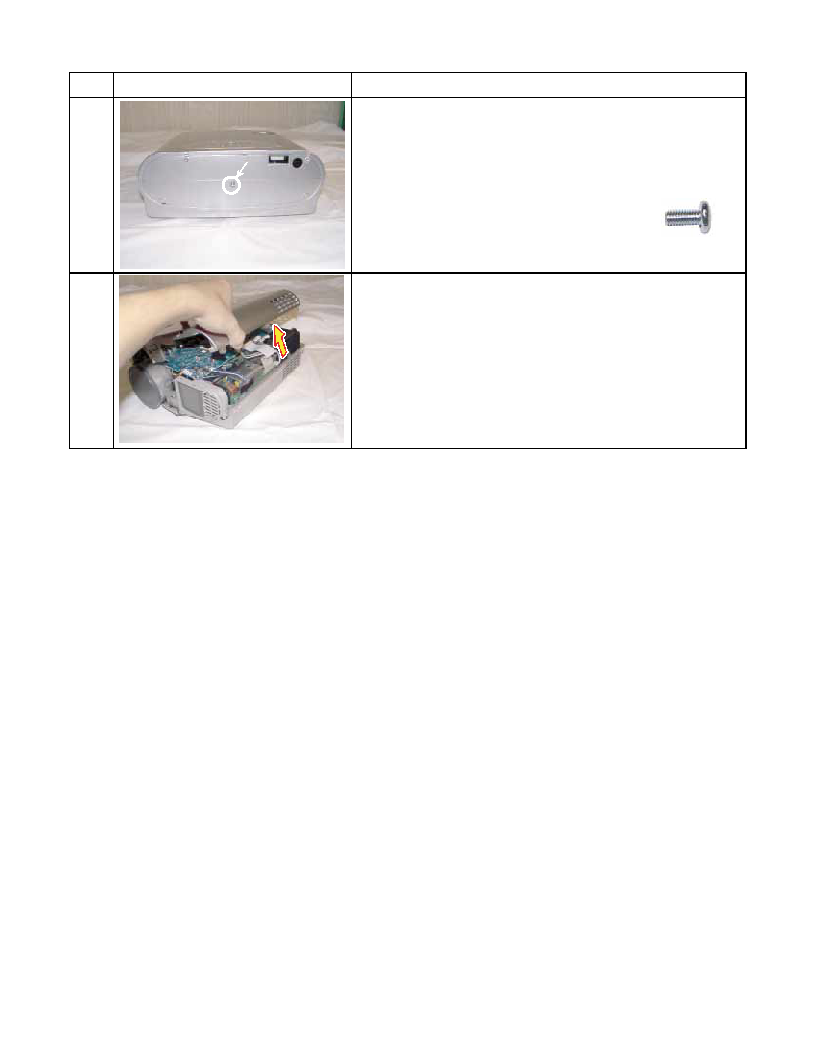
3-2. Top Cover (Continued)
1-4
Step
Figure
Explanation
6
7
[Rear]
Remove 1 screws (M2 x 6).
Screw : type [M-1]
Top cover can be removed by lifting left edge.