PRINTED IN JAPAN, Nov., 2001
FILE NO. 330-200106
SAFETY PRECAUTION
WARNING: Service should not be attempted by anyone unfamiliar with the necessary precautions on this
projector. The following are the necessary precautions to be observed before servicing this chassis.
1 . An isolation Transformer should be connected in the power line between the projector and the AC Iine
before any service is performed on the projector.
2. When replacing a chassis in the cabinet, always be certain that all the protective devices are put back in
place, such as; non-metallic control knobs, insulating covers, shields, isolation resistor-capacitor network
etc.
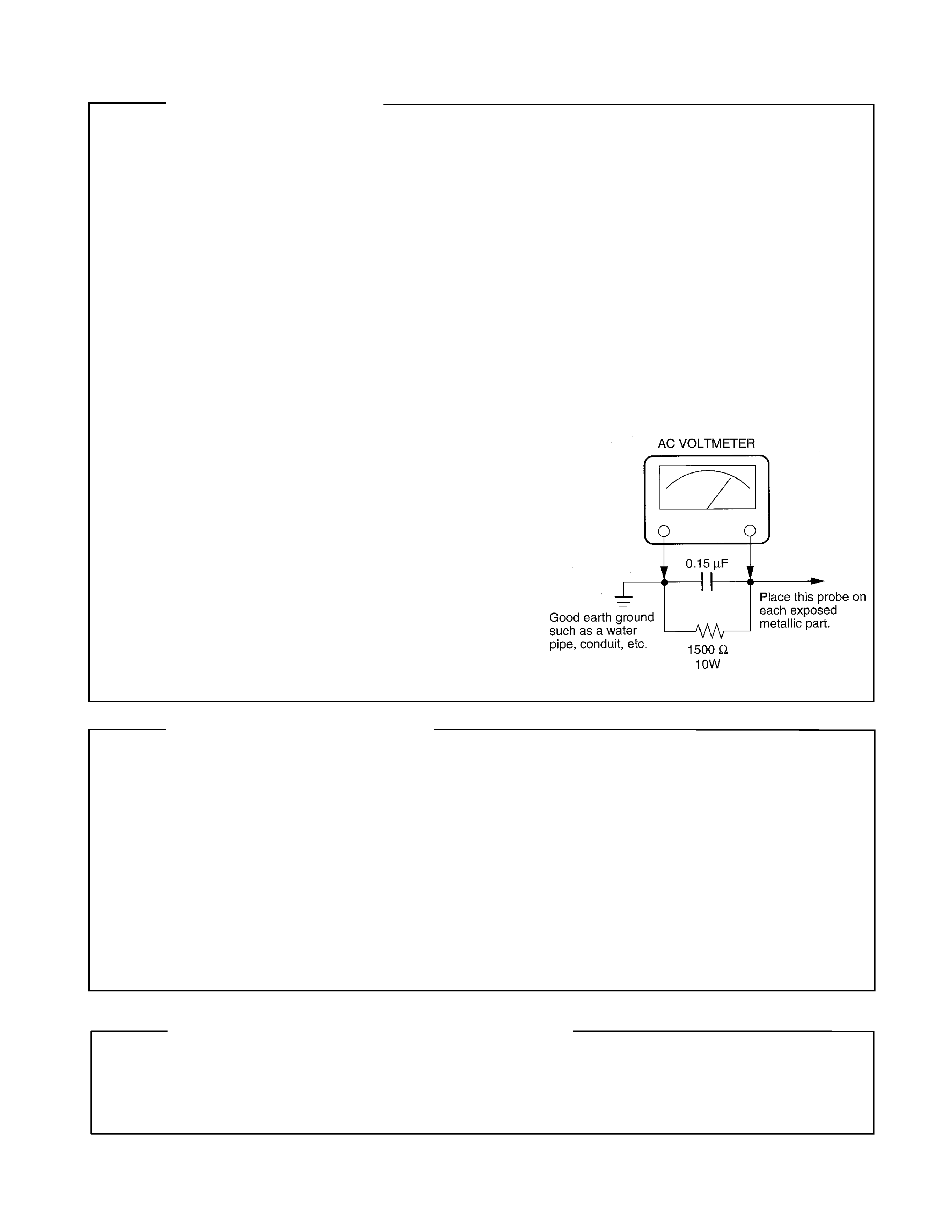
3. Before returning the set to the customer, always perform an AC Ieakage current check on the exposed
metallic parts of the cabinet, such as terminals, screwheads, metal overlays, control shafts etc. to be sure
the set is safe to operate without danger of electrical shock. Plug the AC Iine cord directly into a AC outlet
(do not use a line isolation transformer during this check). Use an AC voltmeter having 5000ohm per volt or
more sensitivity in the following manner: Connect a1500ohm 10W resistor, paralleled by a 0.15 µF, AC type
capacitor, between a known good earth ground (water
pipe, conduit, etc.) and the exposed metallic parts, one
at a time. Measure the AC voltage across the combina-
tion of 1500ohm resistor and 0.15 µF capacitor. Reverse
the AC plug at the AC outlet and repeat AC voltage mea-
surements for each exposed metallic part. Voltage mea-
sured must not exceed 5.25V(rms). This corresponds
to 3.5 mA(AC). Any value exceeding this limit consti-
tutes a potential shock hazard and must be corrected
immediately.
PRODUCT SAFETY NOTICE
Many electrical and mechanical parts in this chassis have special safety-related characteristics. These charac-
teristics are often passed unnoticed by a visual inspection and the protection afforded by them cannot neces-
sarily be obtained by using replacement components rated for higher voltage, wattage, etc. Replacement parts
which have these special safety characteristics are identified in this manual and its supplements; electrical
components having such features are identified by the international hazard symbols on the schematic diagram
and the parts list.
Before replacing any of these components, read the parts list in this manual carefully. The use of substitute
replacement parts which do not have the same safety characteristics as specified in the parts list may create
shock, fire or other hazards.
ULTRAVIOLET DANGER IN SERVICE MODE
Eye damage may result from directly viewing the light produced by the lamp used in this product. Always turn
off lamp before opening this cover. Ultraviolet radiation eye protection required during servicing.
TDP-T3 / TDP-S3 / TDP-MT5 Service Manual

TDP-S3/TDP-T3/TDP-MT5 Service Manual
3
Table of Contents
Table of Contents .......................................................................................................... 3
Safety Precautions ........................................................................................................ 5
Important Precautions .................................................................................................. 5
Important Safety Instructions ...................................................................................... 6
Introducing the TDP-T3, TDP-S3 and TDP-MT5 ......................................................... 7
Parts Replacement ........................................................................................................ 8
Replaceable Part Hierarchy ..................................................................................................8
Exploded views .....................................................................................................................9
Remove and replace the focus and zoom rings..................................................................11
Remove and the front bezel and front bezel vent ...............................................................13
Remove and replace the lamp door and lamp module .......................................................17
Remove and replace the top case ......................................................................................20
Remove and replace the keypad ........................................................................................23
Remove and replace the front fan.......................................................................................24
Remove and replace the speaker assembly .......................................................................26
Remove the controller ECA.................................................................................................29
Install the controller ECA.....................................................................................................32
Remove and replace the I/O EMI shield .............................................................................35
Remove and replace the chassis and power supply...........................................................36
Remove and replace the rear bezel ....................................................................................40
Remove and replace the chassis ........................................................................................43
Remove and replace the lamp fan ......................................................................................44
Remove and replace the lamp blower.................................................................................46
Remove and replace the power supply...............................................................................48
Remove and replace the power supply fan and safety switch cable...................................52
Remove and replace the power supply fuse .......................................................................54
Remove and replace the safety switch assembly ...............................................................55
Remove and replace the optical engine..............................................................................57
Remove and replace the bottom case ................................................................................59
Software ....................................................................................................................... 60
Downloading software to your computer.............................................................................60
Install the Software on the Computer..................................................................................61
Upgrading the software in the TDP-T3................................................................................64
Functional Tests.......................................................................................................... 70

TDP-S3/TDP-T3/TDP-MT5 Service Manual
4
Troubleshooting.......................................................................................................... 74
Troubleshooting Power Problems .......................................................................................75
Troubleshooting Image Problems .......................................................................................81
Troubleshooting Keypad Problems .....................................................................................84
Troubleshooting Remote Problems.....................................................................................85
Troubleshooting Menu Problems ........................................................................................86
Troubleshooting Audio Problems ........................................................................................87
Block Diagram.....................................................................................................................88
Check controller voltages....................................................................................................89
Power up with top case removed to check fans and voltages ............................................90
Check the thermal switch ....................................................................................................93
Check the color wheel and reseat the cable .......................................................................94
Using the keypad to power up the projector........................................................................98
Parts Lists.................................................................................................................. 100
Replaceable parts by alphabetic listing.............................................................................100
Replaceable parts by numeric listing ................................................................................103
Fasteners and Torque Settings.........................................................................................106
Standard Accessories .......................................................................................................107
The lightning flash with arrowhead
symbol, within an equilateral triangle,
is intended to alert the user to the
presence of uninsulated "dangerous
voltage" within the product's
enclosure that may be of sufficient
magnitude to constitute a risk of
electric shock to persons.
The exclamation point within an
equilateral triangle is intended to
alert the user to the presence of
important operating and
maintenance (servicing) instructions
in the literature accompanying the
appliance.
WARNING: TO REDUCE THE RISK OF FIRE OR ELECTRIC SHOCK, DO NOT EXPOSE THIS
APPLIANCE TO RAIN OR MOISTURE. DANGEROUS HIGH VOLTAGES ARE
PRESENT INSIDETHE ENCLOSURE. DO NOT OPEN THE CABINET. REFER
SERVICING TO QUALIRED PERSONNEL ONLY.
CAUTION:
Laser beam is emitted when the laser button of the remote control is pressed. Do not
look from the front of the remote control. Do not face toward a person or to a mirror.
FCC Radio Frequency Interference Statement
Note:
This equipment has been tested and found to comply with the limits for a Class A
digital device, pursuant to part 15 of the FCC Rules. These limits are designed to
provide reasonable protection against harmful interference when the equipment is
operated in a commercial environment. This equipment generates, uses, and can
radiates radio frequency energy and, if not installed and used in accordance with the
instruction manual, may cause harmful interference to radio communications.
Operation of this equipment in a residential area is likely to cause harmful
interference in which case the user will be required to correct the interference at his
own expense.
WARNING: Changes or modifications made to this equipment, not expressly approved by
Toshiba, or parties authorized by Toshiba, could void the user's authority to operate
the equipment.
Notice:
This Class A digital apparatus complies with Canadian ICES-003.
Cet appareil numérique de la classe A est conforme à la norme NMB-003 du
Canada.
IMPORTANT PRECAUTIONS
Save Original Packing Materials
The original shipping carton and packing materials will come in
handy if you ever have to ship your LCD projector. For maximum
protection, repack the set as it was originally packed at the factory.
Avoid Volatile Liquid
Do not use volatile liquids, such as an insect spray, near the unit.
Do not leave rubber or plastic products touching the unit for a long
time. They will mar the finish.
Moisture Condensation
Never operate this unit immediately after moving it from a cold
location to a warm location. When the unit is exposed to such a
change in temperature, moisture may condense on the crucial
internal parts. To prevent the unit from possible damage, do not use
the unit for at least 2 hours when there is an extreme or sudden
change in temperature.
In the spaces provided below, record the Model and Serial No. Iocated
at the rear of your LCD projector.
Mode No.
Serial No.
Retain this information for future reference.
SAFETY PRECAUTIONS
TDP-T1 / TDP-S2 Service Manual
TDP-T3 / TDP-S3 / MT5 Service Manual
5