
SERVICE MANUAL
PUBLISHED IN JAPAN, Dec., 1998
FILE NO. 2B0-9815
SX-2808
CORDLESS TELEPHONE

-- 1 --
CONTENTS
SAFETY PRECAUTIONS ...................................................................................................................... 1
OPERATING CONTROLS ..................................................................................................................... 2
BLOCK DIAGRAMS ............................................................................................................................... 3
SCHEMATIC DIAGRAMS ...................................................................................................................... 5
TROUBLESHOOTING HINTS ............................................................................................................. 13
IC AND TRANSISTOR VOLTAGE CHART ......................................................................................... 19
SEMICONDUCTOR LEAD IDENTIFICATION ..................................................................................... 29
ELECTRICAL PARTS LOCATION ...................................................................................................... 37
WIRING DIAGRAMS ........................................................................................................................... 41
EXPLODED VIEW AND MECHANICAL PARTS LIST ........................................................................ 43
PARTS LIST ........................................................................................................................................ 47
ASSEMBLY PARTS LIST .................................................................................................................... 65
SPECIFICATIONS ............................................................................................................................... 66
SUPPLEMENT FOR CHANGE NOTICE ............................................................................................. 70
SAFETY PRECAUTIONS
Before returning any models to the customer, a safety check of the entire instrument should be made.
The service technician must be sure that no protective device built into the instrument by the manufacturer
has become defective or inadvertently degraded during servicing.
1. WARNING:
Alterations of the design or circuitry of these models should not be made.
Any design changes or additions such as, but not limited to, circuit modifications, auxiliary speaker
jacks, switches, grounding, active or passive circuitry, etc. may alter the safety characteristics of these
models and potentially create a hazardous situation for the user.
Any design alterations or additions will void the manufacturer's warranty and will further relieve the
manufacturer of responsibility for personal injury or property damage resulting therefrom.
2. PRODUCT SAFETY NOTICE
Many electrical and mechanical parts in this chassis have special characteristics. These characteristics
often pass unnoticed and the protection afforded by them cannot necessarily be obtained by using
replacement components rated for higher voltage, wattage, etc. Replacement parts that have these
special safety characteristics are identified in this manual and its supplements; electrical components
having such features are identified by a
in the schematic diagram and the parts list. Before replacing
any of these components, read the parts list in this manual carefully. The use of substitute replacement
parts that do not have the same safety characteristics as specified in the parts list may create shock, fire
or other hazards.
-- 2 --
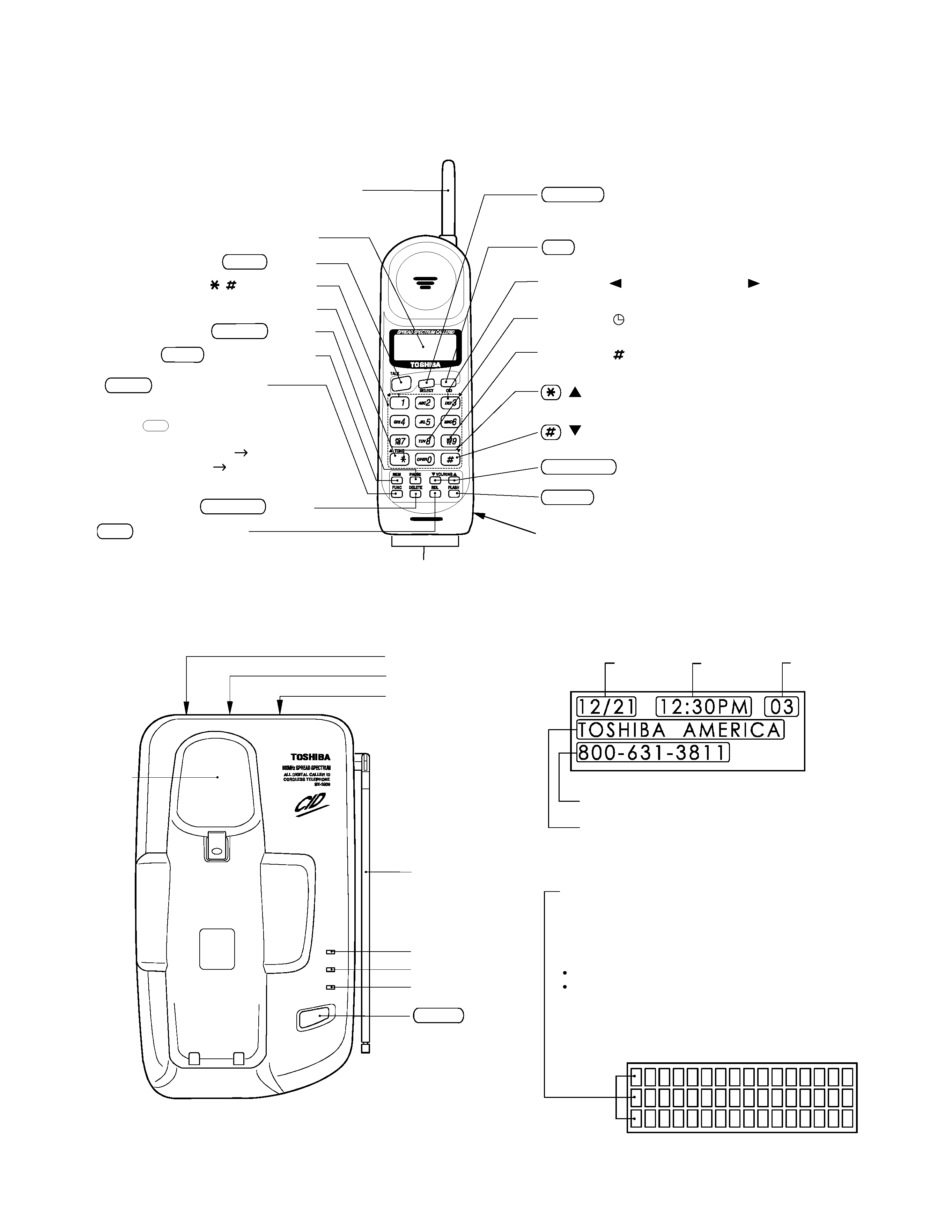
OPERATING CONTROLS
BASE UNIT CONTROLS
HANDSET CONTROLS
(
) button (down arrow button)
Used to scroll down the display screen.
(
) button (up arrow button)
Used to scroll up the display screen.
0-9, ,
Dial buttons
TONE button
Battery compartment
VOL/RING button
FUNC (Function) button
Press to enter the Function Mode to
perform various settings. Each time
the
button is pressed, the
menu changes in the following order:
AUTO TALK ON/OFF
CIDCW ON/OFF
AREA CODE
CID (Caller ID) button
Press to enter the caller ID mode.
TALK button
Liquid Crystal Display (LCD)
Antenna
Charging contacts
Number 1 ( ) button, Number 3 ( ) button
Used for long distance dialing.
Number 8 (
) button (time button)
Used to display the date and time of the received calls.
Number 9 (
) button
Used to display the number of calls attempted by a caller
.
FUNC
DELETE button
FLASH button
MEM (Memory) button
PAUSE button
SELECT
button
Press to select a data from caller ID memory on
storing, editing, and deleting.
RDL (Redial) button
Press to redial the last number dialed.
IN USE
CHARGE
POWER
PAGE
IN USE LED
CHARGE LED
POWER LED
PAGE button
Cradle
LINE modular jack
DC IN 9V jack
Tone/Pulse switch
Base antenna
Dot matrix display
16 digits by 3 lines dot matrix LCD. Shows the time, caller
ID, memory location, instructions, error messages, and
other information.
The back light of the LCD operates inthe following manner:
Turns on during an incoming CID call.
Turns on for 5 seconds and then off
-when a button is pressed (except in battery low status).
Date
Time
Number of calls
Caller
s telephone number
Caller
s name
-- 3 --
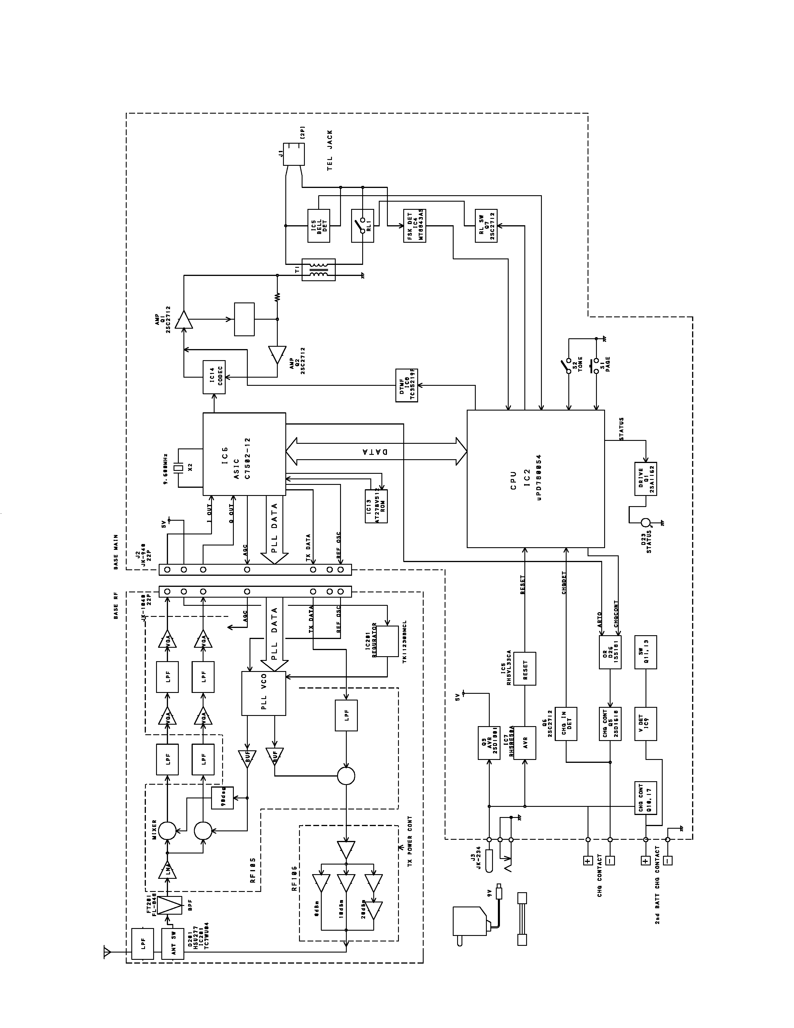
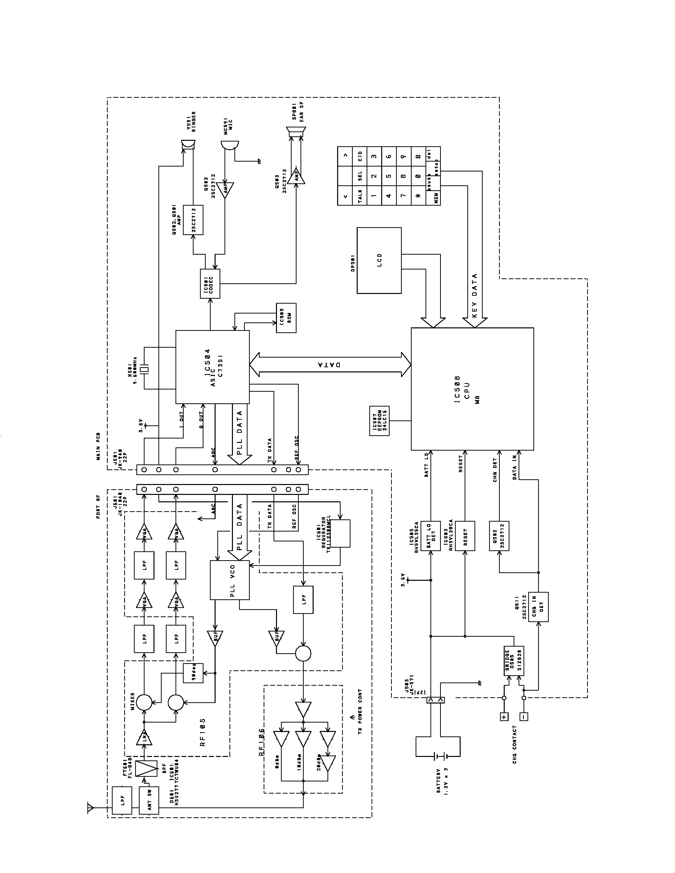
BLOCK DIAGRAMS
Base
-- 4 --
Handset