Q
Q
Q
Q u
u
u
u iiiic
c
c
c k
k
k
k S
S
S
S e
e
e
e ttttu
u
u
u p
p
p
p G
G
G
G u
u
u
u iiiid
d
d
d e
e
e
e
SD-V57HTSU
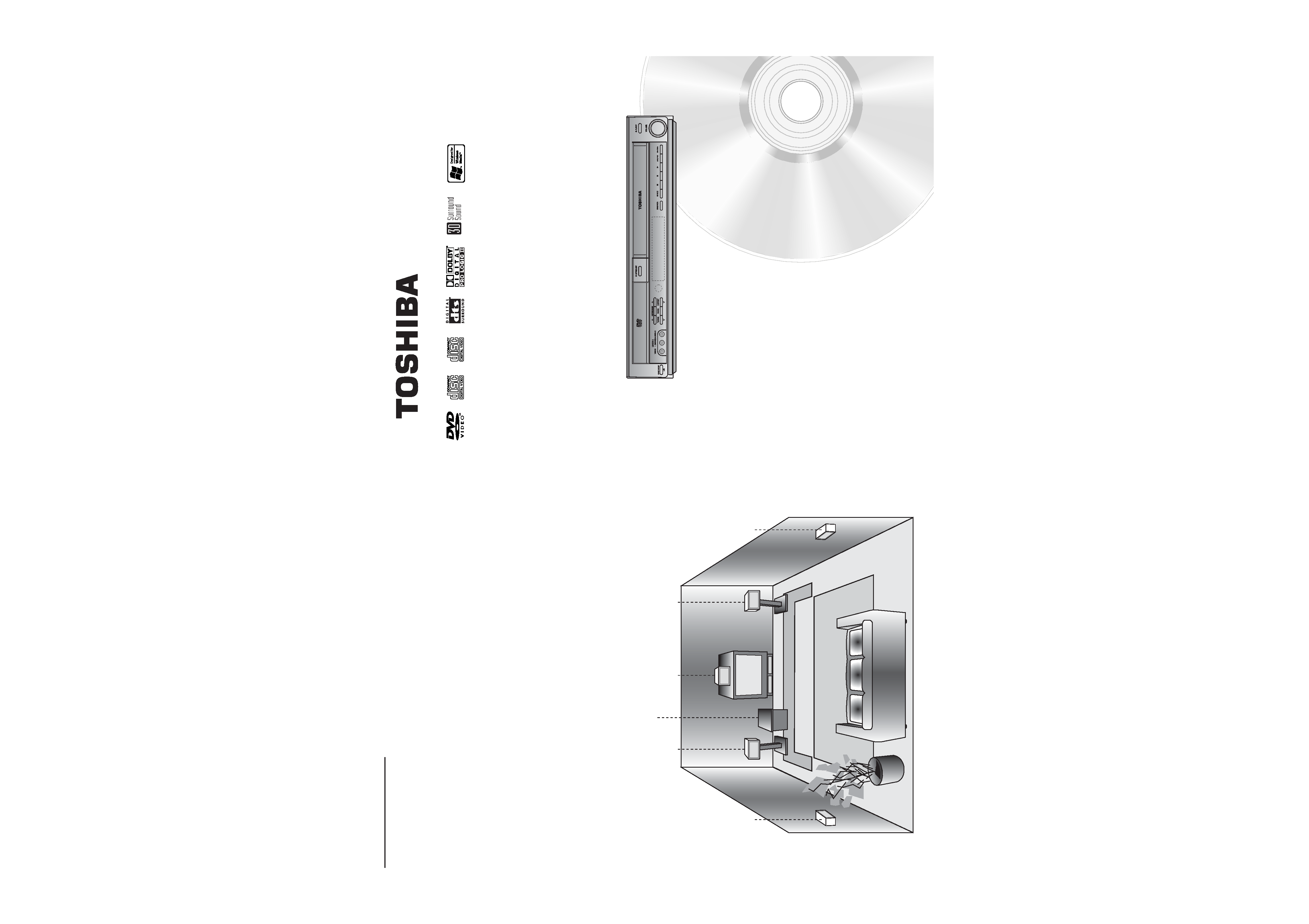
Speaker Positioning
For a normal setup use 6 speakers (2 front speakers, center speaker, 2 rear speakers and subwoofer).
· Front Speakers
Set up the speakers at an equal distance from your listening position. And by hearing position, set up an interval
between speakers of 45 degree.
· Center Speaker
It is ideal if the center speaker and front speakers at the same height. But normally place the center speaker above or
below the television as shown below.
· Rear Speakers
Place the rear surround speakers to the left and right behind the primary listening area. These speakers recreate
sound motion and atmosphere required for surround playback. For best results, do not install the rear speakers too far
behind the listening position, install them at or above the level of the listener's ears. It is also effective to direct the
rear speakers towards a wall or ceiling to further disperse the sound.
In the case of a smaller room size, if the audience is near to the rear wall, set the rear speakers opposite each other,
and set the rear speakers 60 - 90 cm above the listener's ears.
·Subwoofer
This can be placed in any front position.
Rear Speaker
(Left)
Front Speaker
(Left)
Center
Speaker
Subwoofer
Front Speaker
(Right)
Rear Speaker
(Right)
P/N: 3840R-Q????
©2005 Toshiba Corporation
This device does not tape-record copy protected DVD Video Discs.
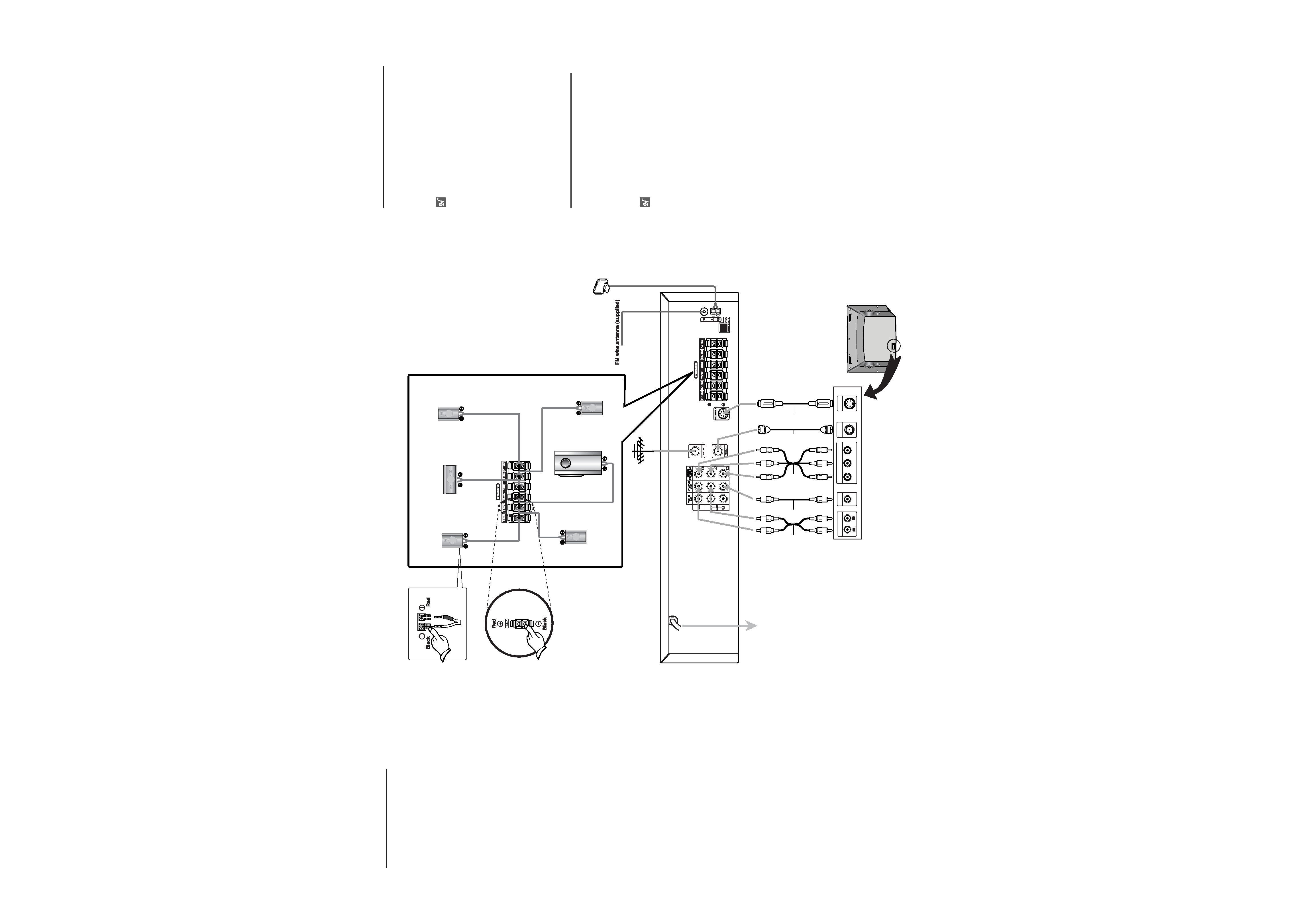
To Wall Outlet
Before you connect this system
to your TV, be sure to turn off
the power and unplug both units
from the wall power outlet
before making any connections.
Front Speaker
(Right)
Front Speaker
(Left)
Center
Speaker
Rear speaker
(Left surround)
Subwoofer
Rear speaker
(Right surround)
AM loop antenna (supplied)
R
ANTENNA
INPUT
L
R
Y
Pb
Pr
COMPONENT/PROGRESSIVE
SCAN VIDEO INPUT
AUDIO INPUT
L
VIDEO
INPUT
S-VIDEO
INPUT
Rear of TV
S
A
V
C
Antenna
Speaker System Connections
Connect the speakers using the supplied
speaker cords by matching the colors of the
terminals and those of the cords. To obtain the
best possible surround sound, adjust the
speaker parameters (distance, level, etc.).
otes
Be sure to match the speaker cord to the
appropriate terminal on the components: 3
to 3 and # to #. If the cords are reversed,
the sound will be distorted and lack bass.
If you use front speakers with low maximum
input rating, adjust the volume carefully to
avoid excessive volume output to the
speakers.
Do not disassemble the front covers of
supplied speakers.
Radio Antenna Connections
Connect the supplied AM/FM antennas for
radio listening.
11
Connect the AM loop antenna to the AM
antenna connectors.
2
2
Connect the FM wire antenna to the FM
antenna connectors.
otes
To prevent noise pickup, keep the AM loop
antenna away from the DVD/VCR Receiver
and other components.
Be sure to fully extend the FM wire antenna.
After connecting the FM wire antenna, keep
it as horizontal and flat as possible.
TV Connections
Make one of the following connec-
tions, depending on the capabilities of
your TV.
Video connection
Connect the DVD/VCR VIDEO OUT jack
on the DVD/VCR Receiver to the Video
in jack on the TV using the supplied
video cable (V).
S-Video connection
Connect the S-VIDEO OUT jack on the
DVD/VCR Receiver to the S-Video in
jack on the TV using the S-Video cable
(S).
Component Video
(ColorStream®) connection
Connect the COMPONENT/PROGRES-
SIVE SCAN VIDEO OUT jacks on the
DVD/VCR Receiver to the corresponding
in jacks on the TV using Y Pb Pr cables
(C).
Progressive Scan (ColorStream
Pro®) connection
If your television is a high-definition or
"digital ready" television, you may take
advantage of the
DVD/VCR Receiver's
progressive scan output for the highest
video resolution possible.
If your TV does not accept the
Progressive Scan format, the picture will
appear scrambled if you try Progressive
Scan on the
DVD/VCR Receiver.
Connect the COMPONENT/PRO-
GRESSIVE SCAN VIDEO OUT jacks
on the DVD/VCR Receiver to the cor-
responding in jacks on the TV using Y
Pb Pr cable (C).