DVD
SERVICE
FILE
810-200403
SD-P1400U
MANUAL
NO.
VIDEO PLAYER
SD-KP12U
DOCUMENT CREATED IN JAPAN, June, 2004
REVISION 1
When the power supply is being turned on, you may not remove this laser cautions label. If it removes, radiation of laser
may be received.
LASER BEAM CAUTION LABEL
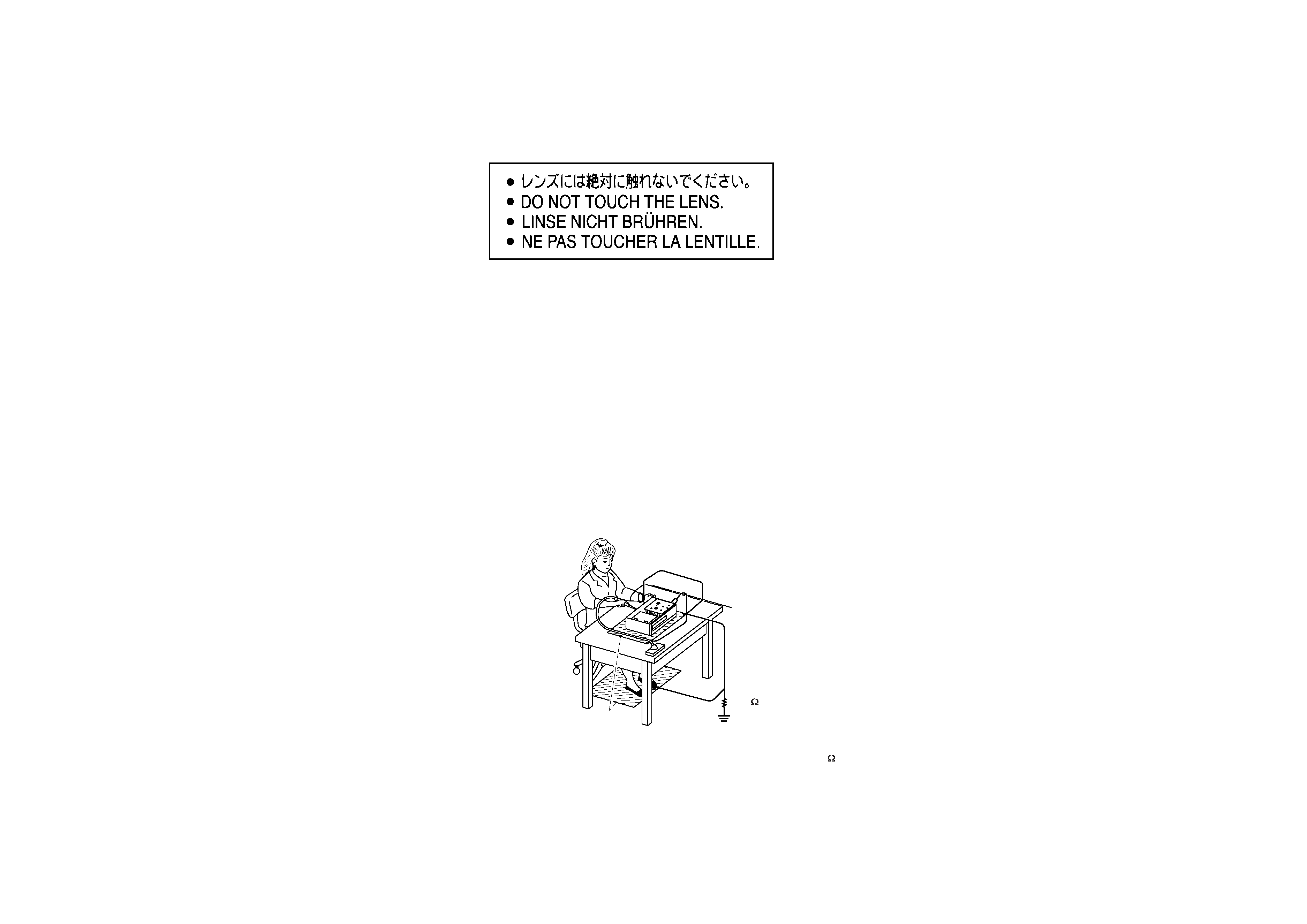
PREPARATION OF SERVICING
Pickup Head consists of a laser diode that is very susceptible to external static electrocity.
Although it operates properly after replacement, if it was subject to electrostatic discharge during replacement,
its life might be shortened. When replacing, use a conductive mat, soldering iron with ground wire,etc. to
protect the laser diode f
rom damage by static electricity.
And also, the LSI and IC are same as above.
Soldering iron
with ground wire
or ceramic type
Ground conductive
wrist strap for body.
Conductive mat
The ground resistance
between the ground line
and the ground is less than 10
1M
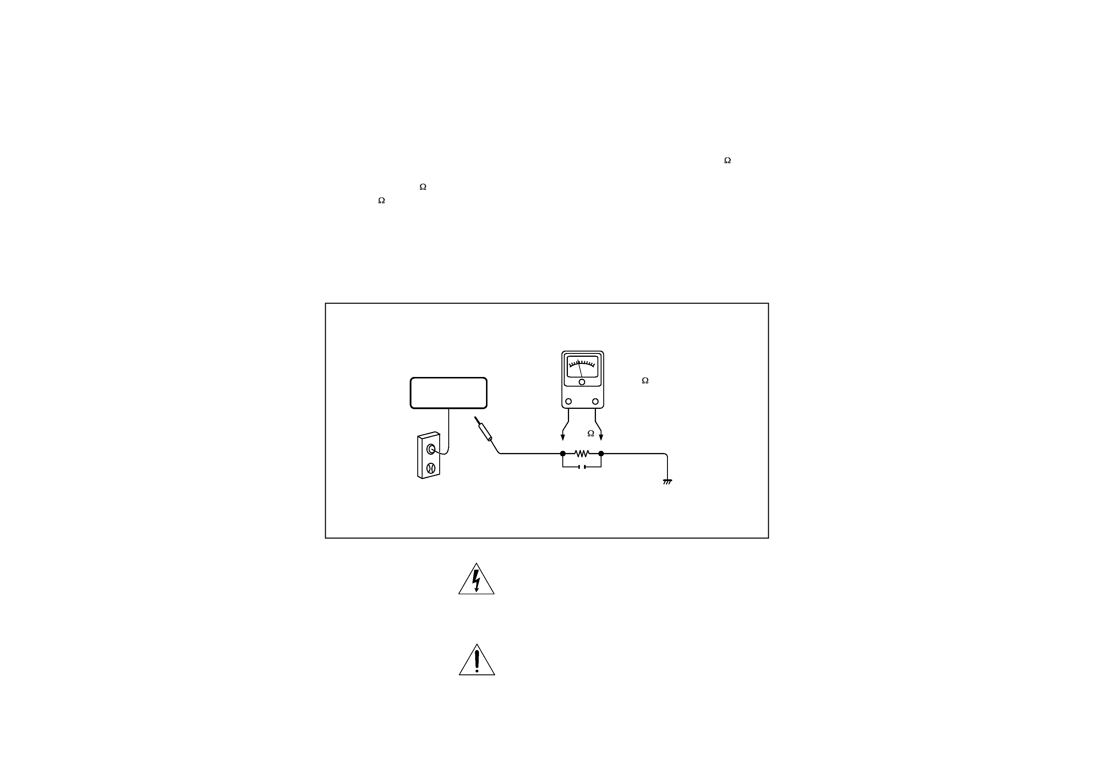
SAFTY NOTICE
Plug the AC line cord directly into a 120V AC outlet (do
not use an isolation transformer for this check). Use an
AC voltmeter, having 5000 per volt or more sensitivity.
Connect a 1500 10W resistor,paralleled by a 0.15uF
150V AC capacitor between a k
nown good earth ground
(water pipe, conduit, etc.) and all exposed metal parts of
cabinet (antennas, handle bracket, metal cabinet
screwheads, metal overlays, control shafts, etc.).
SAFTY PRECAUTIONS
LEAKAGE CURRENT CHECK
Measure the AC voltage across the 1500 resistor.
The test must be conducted with the AC switch on and
then repeated with the AC switch off. The AC voltage
indicated by the meter may not exceed 0.3V.A reading
exceeding 0.3V indicates that a dangerous potential
exists, the fault must be located and corrected.
Repeat the above test with the DVD VIDEO PLAYER
power plug reversed.
NEVER RETURN A DVD VIDEO PLAYER TO THE
CUSTOMER WITHOUT TAKING NECESSARY
CORRECTIVE ACTION.
READING SHOULD NOT EXCEED 0.3V
DVD VIDEO PLAYER
AC OUTLET
AC VOLTMETER
Test all exposed metal.
Voltmeter Hook-up for Leakage Current Check
0.15uF 150V AC
1500
10W
(5000 per volt
or more sensitivity)
Good earth ground
such as a water pipe,
conduit, etc.
The lightning flash with arrowhead symbol, within an
equilateral triangle, is intended to alert the user to the
presence of uninsulated "dangerous voltage" within the
product's enclosure that may be of sufficient magnitude to
constitute a risk of electric shock to persons.
The exclamation point within an equilateral triangle is
intended to alert the user to the presence of important
operating and maintenance (servicing) instructions in the
literature accompanying the appliance.
1
2
3
4
5
6
7
8
KEYIN3
KEYIN2
KEYIN1
KEYIN0
KEYOUT0
KEYOUT1
KEYOUT2
KEYOUT3
1
2
3
4
5
6
7
8
1
2
3
4
5
6
7
8
9
10
11
12
13
14
15
16
17
18
19
20
21
22
23
24
NC
DVDVCC
V20
GND
F
E
CD/DVD SW
RF
C
D
B
A
VRCD
VRDVD
DVDMD
CDLD
GND
DVDLD
NC
AVCC
FCS-
TRK+
TRK-
FCS+
1
2
3
4
5
6
7
8
9
10
11
12
13
14
15
16
17
18
19
20
21
22
23
24
1
2
3
4
5
6
1
2
3
4
5
6
SP-
SP+
SL+
SL-
GND
LIMIT
1
2
3
4
5
6
7
8
9
10
11
12
13
14
15
16
17
18
19
20
1
2
3
4
5
6
7
8
9
10
11
12
13
14
15
16
17
18
19
20
1
2
3
4
5
6
7
8
9
10
11
12
13
14
15
16
17
18
19
20
1
2
3
4
5
6
7
8
9
10
11
12
13
14
15
16
17
18
19
20
1
2
3
4
GND
GND
HV
HV
1
2
3
4
1
2
3
4
1
2
3
4
1
2
3
4
5
6
7
8
9
10
11
12
13
14
15
16
17
18
19
20
21
22
23
24
25
26
27
28
29
30
1
2
3
4
5
6
7
8
9
10
11
12
13
14
15
16
17
18
19
20
21
22
23
24
25
26
27
28
29
30
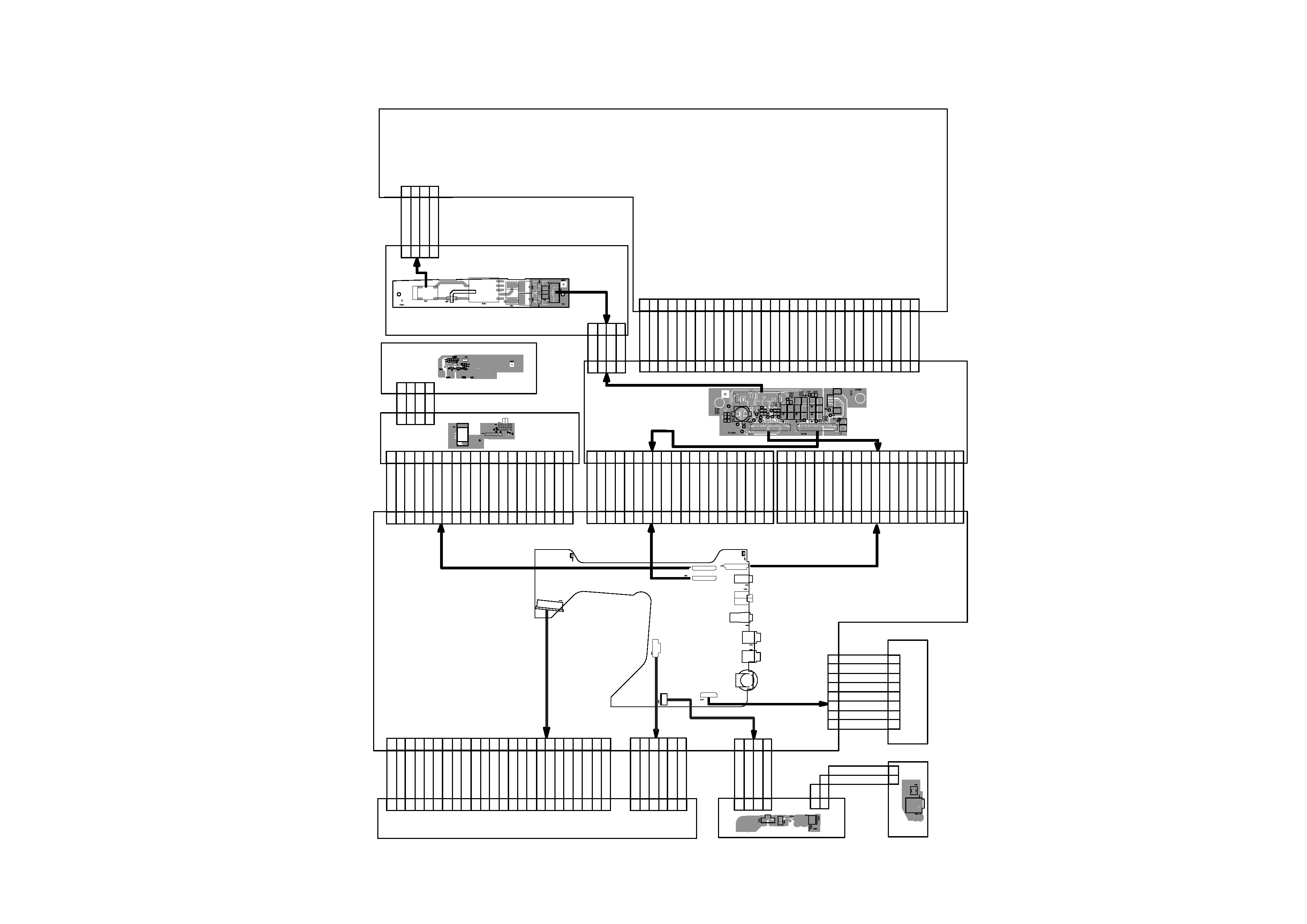
XS402
XS401
XS403
FUNCTION BUTTON PCB
MECHANISM
MAIN PCB
IF PCB
LCD
HIGH VOLTAGE PCB
SWITCH PCB
JS103
JS102
JS104
JS105
XS302
XS303
XS301
XS304
XS102
XS101
COMS
-16V
SPIO
NC
NC
CLD
MODE1
GND
3.3V
GND
SPOI
GND
R
G
B
TF +5V
TF +5V
GND
GND
+13V
I23
GND
GND
MODE2
CLS
SPS
3.3V
GND
3.3V
3.3V
GND
GND
GND
-14.5V
GND
+16.5V
GND
GND
VDD1-3V
VDD1-3V
GND
GND
GND
GND
GND
BRIGHT-CO
TFT ON/OFF
TFT-HV
TFT-HV
TFT-HV
VCOMS
GND
GND
GND
G
B
R
GND
MODE2
MODE1
SPOI
SPIO
SPS
CLD
CTR
CLS
GND
GND
TF +5V
TF +5V
HV CRITICAL
NC
HV~
HV~
POWER PCB B
POWER PCB A
DC
DCIN
POWERSW
GND
1
2
3
4
1
2
3
4
1
2
1
2
DC
GND
XS101
SW101
XS104
1
2
3
4
5
6
7
8
9
10
11
12
13
14
15
16
17
18
19
20
1
2
3
4
5
6
7
8
9
10
11
12
13
14
15
16
17
18
19
20
LI-DC
LI-DC
LI-DC
GND
GND
GND
TS
GND
AUXSW
GND
Y1+
Y1-
C-OUT
GND
Y2+
Y2-
Y-OUT
Y3+
Y3-
VIDEO OUT
1
2
3
4
1
2
3
4
GND
GND
RT1
B+1
JS106
BATTERY PCB
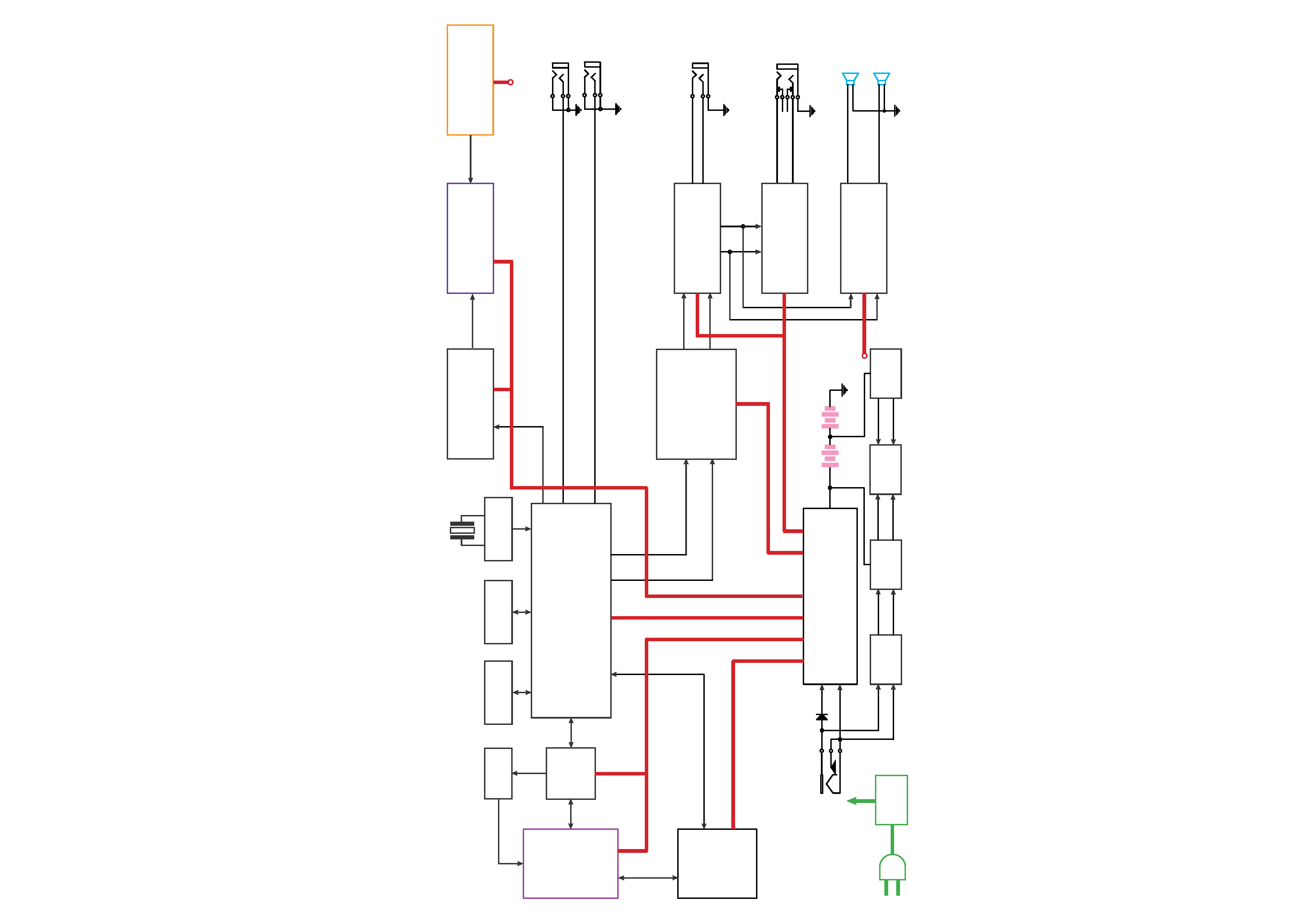
SERVO & DVD PROCESSOR
MPEG-2 DECODER
& VIDEO ENCODER
D2881
OVERALL BLOCK DIAGRAM
AC
Adapter
DC IN +12V
DC / DC
(R1224)
DC / DC
(R1224)
(TPS5100)
(BQ2057C)
(TPC8207)
(VG202C)
110~240V
50/60Hz
BATTERY
DV23
PU mechanism
DRIVER
(BA5954FP)
RF AMP
D2891
8M FlashROM
MX29LV008TTC-70
64M SDRAM
NT56V6620C0T-75S
TC4W53
27MHz
AUDIO D/A
(PCM1742)
UPD5100
TFT MONITOR
AUDIO AMP
(JRC4558)
PHONE AMP
(JRC4580)
SPEAKER AMP
(D2822)
HIGH VOLTAGE ASS'Y
74HCU04
27MHz
VIDEO OUT
AUDIO OUT
PHONE OUT
SPEAKER LOUT
SPEAKER ROUT
L
R
L
R
R
L
DRIVER +5V
+5V
AUDIO +/-5V
+3.3V
AUDIO +5V
TFT POWER
+5V -14.5V +16V
S-VIDEO OUT
DC 12V
DC 12V