DVD VIDEO PLAYER
SERVICE MANUAL
Jun., 2002 5
FILE NO. 810-200207
SD-2550A
SD-2550H
SD-2550T
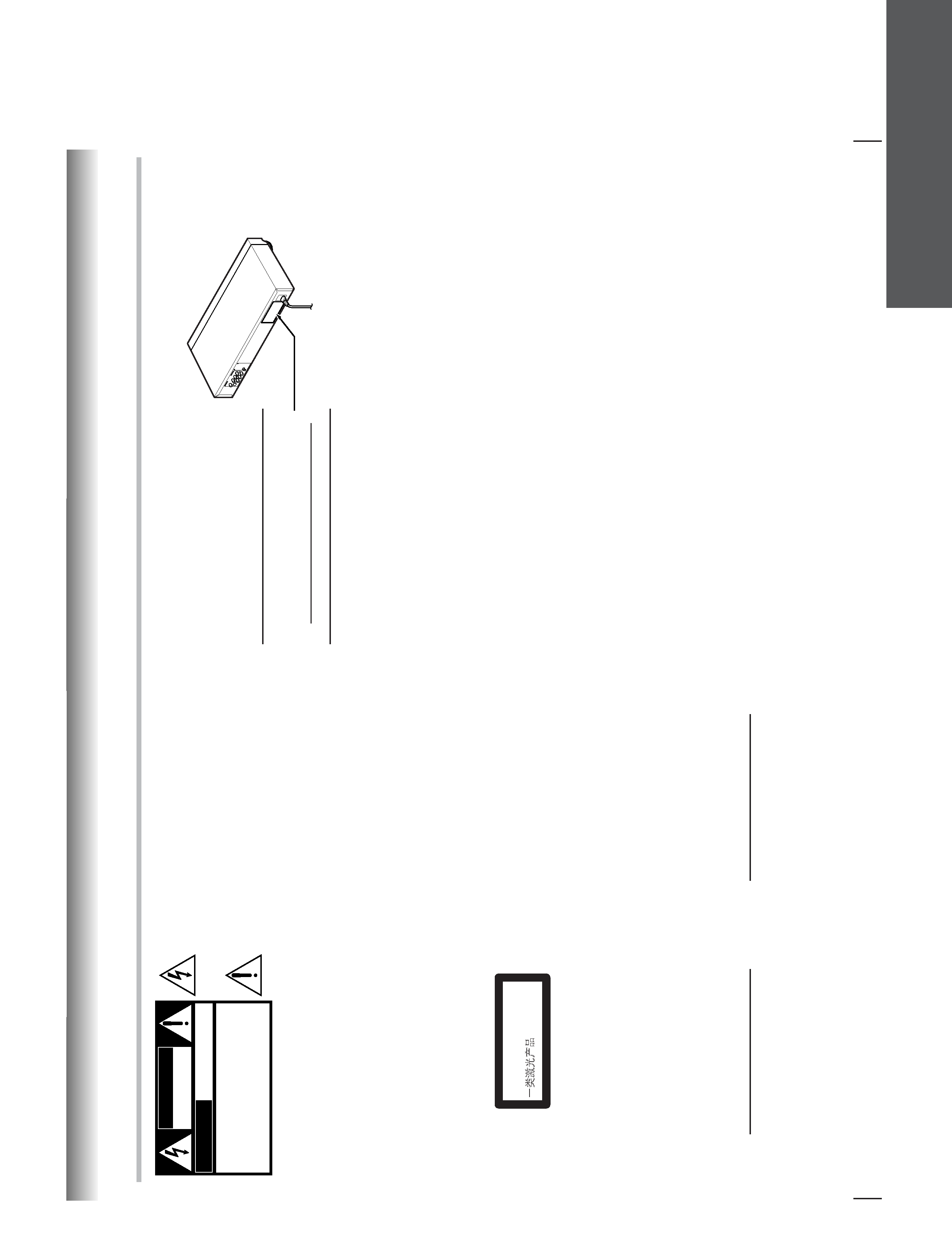
LASER BEAM CAUTION LABEL
When the power supply is being turned on, you may not remove this laser cautions label. If it removes, radiation of a laser
may be recceived.
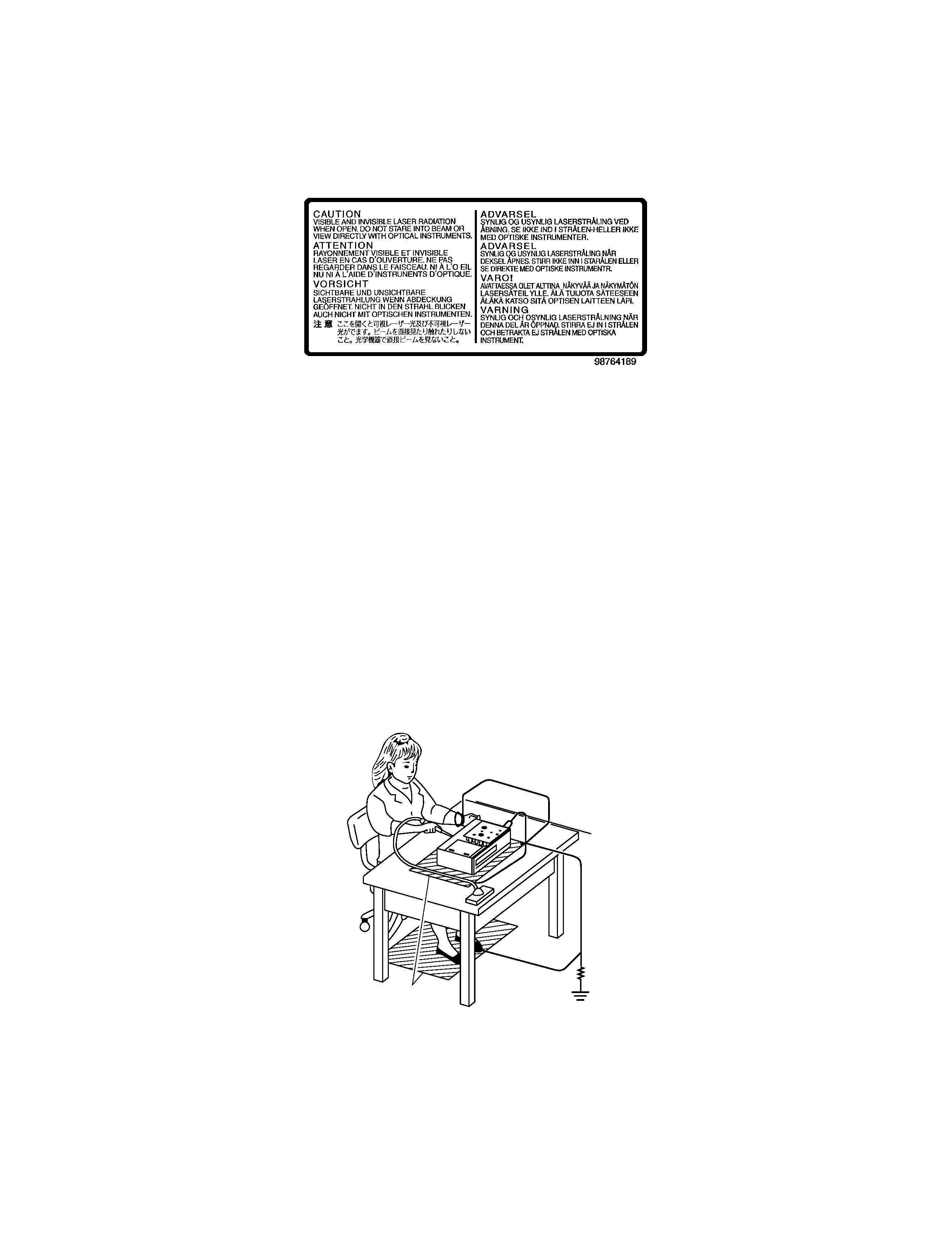
PREPARATION OF SERVICING
Pickup Head consists of a laser diode that is very susceptible to external static electricity.
Although it operates properly after replacement, if it was subject to electrostatic discharge during replacement,
its life might be shortened. When replacing, use a conductive mat, soldering iron with ground wire, etc. to
protect the laser diode from damage by static electricity.
And also, the LSI and IC are same as above.
1M9
Ground conductive
wrist strap for body.
Soldering iron
with ground wire
or ceramic type
Conductive mat
The ground resistance
between the ground line
and the ground is less than 109.

SECTION 2
PART REPLACEMENT AND ADJUSTMENT PROCEDURES
SECTION 3
SERVICING DIAGRAMS
1. STANDING PC BOARDS FOR SERVICING ......................... 3-1
2. CIRCUIT SYMBOLS AND
SUPPLEMENTARY EXPLANATION ..................................... 3-2
2-1. Precautions for Part Replacement ..................................... 3-2
2-2. Solid Resistor Indication ..................................................... 3-2
2-3. Capacitance Indication ....................................................... 3-2
2-4. Inductor Indication ............................................................. 3-3
2-5. Waveform and Voltage Measurement .............................. 3-3
2-6. Others ................................................................................... 3-3
3. PRINTED WIRING BOARD AND
SCHEMATIC DIAGRAM .......................................................... 3-4
4. BLOCK DIAGRAMS .................................................................. 3-5
4-1. Overall Block Diagram ....................................................... 3-5
4-2. Power Supply Block Diagram ............................................ 3-7
4-3. Front Display, Power Switch Block Diagram ................... 3-8
4-4. Main Block Diagrams ....................................................... 3-11
5. CIRCUIT DIAGRAMS ............................................................. 3-15
5-1. Power Supply Circuit Diagram ........................................ 3-15
5-2. Front Display, Power Switch Circuit Diagram .............. 3-18
5-3. Main Circuit Diagram ...................................................... 3-21
5-4. Motor System Circuit Diagrams ...................................... 3-33
6. PC BOARDS .............................................................................. 3-35
6-1. Power Supply PC Board ................................................... 3-35
6-2. Power Switch PC Board ................................................... 3-36
6-3. Front Display PC Board ................................................... 3-37
6-4. Main PC Board .................................................................. 3-39
CONTENTS
SECTION 1
GENERAL DESCRIPTIONS
1. OPERATING INSTRUCTIONS ................................................ 1-1
2. LOCATION OF MAIN PARTS AND
MECHANISM PARTS ............................................................. 1-30
2-1. Location of Main Parts ..................................................... 1-30
2-2. Location of Mechanism Parts .......................................... 1-31
2-2-1. Type A ............................................................................ 1-31
2-2-2. Type B ............................................................................ 1-34
1. REPLACEMENT OF MECHANICAL PARTS (TYPE A) .... 2-1
1-1. Cabinet Replacement .......................................................... 2-1
1-1-1. Top Cover ........................................................................ 2-1
1-1-2. Tray Panel ....................................................................... 2-1
1-1-3. Front Panel ...................................................................... 2-2
1-1-4. Tray .................................................................................. 2-2
1-1-5. Rear Panel ........................................................................ 2-2
1-2. PC Board Replacement ....................................................... 2-3
1-2-1. Main PC Board ............................................................... 2-3
1-2-2. Power PC board .............................................................. 2-3
1-2-3. Front PC Board ............................................................... 2-4
1-3. Mechanism Parts ................................................................. 2-4
1-3-1. Mechanism Chassis Assembly ........................................ 2-4
2. REPLACEMENT OF MECHANICAL PARTS (TYPE B) .... 2-5
2-1. Cabinet Replacement .......................................................... 2-5
2-1-1. Top Cover ........................................................................ 2-5
2-1-2. Clamper Stay ................................................................... 2-5
2-1-3. Tray Panel ....................................................................... 2-6
2-1-4. Front Panel and Tray ..................................................... 2-6
2-1-5. Rear Panel ........................................................................ 2-7
2-2. PC Board Replacement ....................................................... 2-7
2-2-1. Main PC Board ............................................................... 2-7
2-2-2. Power PC board .............................................................. 2-8
2-2-3. Front PC Board ............................................................... 2-8
2-3. Mechanism Parts ................................................................. 2-8
2-3-1. Mechanism Chassis Assembly ........................................ 2-8
3. TROUBLESHOOTING ............................................................ 1-37
3-1. Main Circuit ....................................................................... 1-37
3-1-1. Servo System .................................................................. 1-37
3-1-2. Location Diagram of Servo Test Point ........................ 1-44
SECTION 4
PARTS LIST
SAFETY PRECAUTION ................................................................. 4-1
NOTICE ............................................................................................. 4-1
ABBREVIATIONS ........................................................................... 4-1
1. Integrated Circuit (IC) ............................................................ 4-1
2. Capacitor (Cap) ....................................................................... 4-1
3. Resistor (Res) ........................................................................... 4-1
4. EXPLODED VIEWS ................................................................... 4-2
4-1. Packing Assembly ................................................................ 4-2
4-2. Chassis Assembly (Type A) ................................................ 4-3
4-3. Mechanism Assembly (Type A) ......................................... 4-4
4-4. Chassis Assembly (Type B) ................................................ 4-5
4-5. Mechanism Assembly (Type B) ......................................... 4-6
5. PARTS LIST ................................................................................ 4-7
Specifications

This page is not printed.
1-1
SECTION
1
GENERAL
DESCRIPTIONS
2
Introduction
W
ARNING:
T
O
REDUCE
THE
RISK
OF
FIRE
OR
ELECTRIC
SHOCK,
DO
NOT
EXPOSE
THIS
APPLIANCE
T
O
RAIN
OR
MOISTURE.
DANGEROUS
HIGH
VOL
T
AGES
ARE
PRESENT
INSIDE
THE
ENCLOSURE.
DO
NOT
OPEN
THE
CABINET
.REFER
SER
VICING
T
O
QUALIFIED
PERSONNEL
ONL
Y
.
CAUTION:
This
Digital
Video
Disc
Pla
y
er
emplo
ys
a
Laser
System.
T
o
ensure
proper
use
of
this
product,
please
read
this
o
wner'
s
man
ual
carefully
and
retain
f
o
r
future
ref
erence
.Should
the
unit
require
maintenance
,contact
an
author
iz
ed
ser
vice
location
-
see
ser
vice
procedure
.
Use
of
controls
or
adjustments
or
perf
or
mance
of
procedures
other
than
those
specified
herein
ma
y
result
in
hazardous
r
adiation
e
xposure
.
T
o
pre
v
ent
direct
e
xposure
to
laser
beam,
do
not
tr
y
to
open
the
enclosure
.
Visib
le
and
in
visib
le
laser
radiation
when
open
and
inter
loc
ks
def
eated.
DO
NO
T
ST
ARE
INT
O
BEAM.
In
the
spaces
pro
vided
belo
w
,record
the
Model
and
Ser
ial
No
.located
on
the
rear
panel
of
y
our
D
VD
video
pla
y
e
r.
Model
No
.
Ser
ial
No
.
Retain
this
inf
or
mation
f
or
future
ref
erence
.
The
lightning
flash
with
arro
whead
symbol,
within
an
equilat-
er
al
tr
iangle
,is
intended
to
aler
tthe
user
to
the
presence
of
uninsulated
"dangerous
v
oltage"
within
the
product'
s
enclo-
sure
that
ma
y
be
of
sufficient
magnitude
to
constitute
a
r
isk
of
electr
ic
shoc
k
to
persons
.
The
e
xclamation
point
within
an
equilater
al
tr
iangle
is
in-
tended
to
aler
tthe
user
to
the
presence
of
impor
tant
oper
at-
ing
and
maintenance
(ser
vicing)
instr
uctions
in
the
liter
ature
accompan
ying
the
appliance
.
WARNING
RISK
OF
ELECTRIC
SHOCK
DO
NOT
OPEN
AVIS
RISQUE
DE
CHOC
ELECTRIQUE
NE
PAS
OUVRIR
WARNING
:
TO
REDUCE
THE
RISK
OF
ELECTRIC
SHOCK,
DO
NOT
REMOVE
COVER
(OR
BACK).
NO
USERSERVICEABLE
PARTS
INSIDE.
REFER
SERVICING
TO
QUALIFIED
SERVICE
PERSONNEL.
SAFETY
PRECAUTIONS
CLASS1
LASER
PR
ODUCT
3
Location
of
the
required
label
WARNING
TO
REDUCE
THE
RISK
OF
ELECTRIC
SHOCK.
DO
NOT
REMOVE
COVER.
REFER
SERVICING
TO
QUALIFIED
SERVICE
PERSONNEL.
TOSHIBA
CORPORATION
SECTION 1
GENERAL DESCRIPTIONS
1. OPERATING INSTRUCTIONS (SD-2550A/H)