DVD VIDEO PLAYER
SERVICE MANUAL
May, 2002
5
FILE NO. 810-200202
SD-220EB
SD-220EE
SD-220EL
SD-120EB
SD-120EE
SD-120EL
SD-222EE
D I G I TA L
V I D E O
SD-220EB
LASER BEAM CAUTION LABEL
When the power supply is being turned on, you may not remove this laser cautions label. If it removes, radiation of a laser
may be recceived.
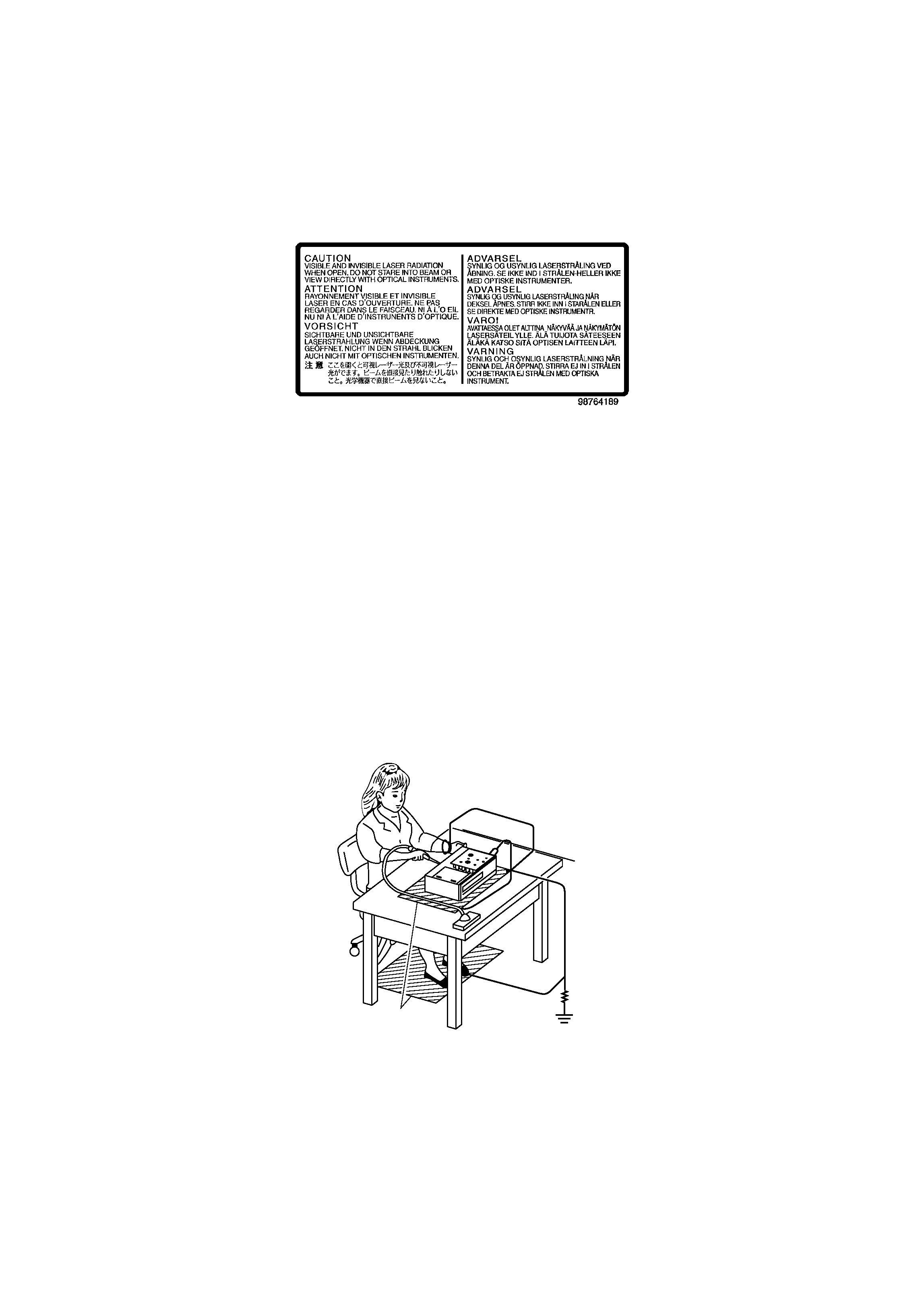
PREPARATION OF SERVICING
Pickup Head consists of a laser diode that is very susceptible to external static electricity.
Although it operates properly after replacement, if it was subject to electrostatic discharge during replacement,
its life might be shortened. When replacing, use a conductive mat, soldering iron with ground wire, etc. to
protect the laser diode from damage by static electricity.
And also, the LSI and IC are same as above.
1M9
Ground conductive
wrist strap for body.
Soldering iron
with ground wire
or ceramic type
Conductive mat
The ground resistance
between the ground line
and the ground is less than 109.

SECTION 2
PART REPLACEMENT AND ADJUSTMENT PROCEDURES
SECTION 3
SERVICING DIAGRAMS
1. STANDING PC BOARDS FOR SERVICING
2. CIRCUIT SYMBOLS AND
SUPPLEMENTARY EXPLANATION
2-1. Precautions for Part Replacement
2-2. Solid Resistor Indication
2-3. Capacitance Indication
2-4. Inductor Indication
2-5. Waveform and Voltage Measurement
2-6. Others
3. PRINTED WIRING BOARD AND
SCHEMATIC DIAGRAM
4. BLOCK DIAGRAMS
4-1. Overall Block Diagram
4-2. Power Supply Block Diagram
4-3. Front Display, Power Switch Block Diagram
4-4. Main Block Diagrams
5. CIRCUIT DIAGRAMS
5-1. Power Supply Circuit Diagram
5-2. Front Display, Power Switch Circuit Diagram
5-3. Main Circuit Diagram
5-4. Output-RGB Circuit Diagram
5-5. Motor System Circuit Diagrams
6. PC BOARDS
6-1. Power Supply PC Board
6-2. Output-RGB PC Board
6-3. Main PC Board
6-4. Front Display PC Board
CONTENTS
SECTION 1
GENERAL DESCRIPTIONS
1. OPERATING INSTRUCTIONS (SD-220EB)
Specifications
2. LOCATION OF MAIN PARTS AND
MECHANISM PARTS
2-1. Location of Main Parts
2-2. Location of Mechanism Parts
2-2-1. Type A
2-2-2. Type B
1. Replacement of Mechanical Parts (Type A)
1-1. Cabinet Replacement
1-1-1. Top Cover
1-1-2. Tray Panel
1-1-3. Front Panel
1-1-4. Tray
1-1-5. Rear Panel
1-2. PC Board Replacement
1-2-1. Main PC Board
1-2-2. Power PC board
1-2-3. Output PC Board
1-2-4. Front PC Board (SD-220)
1-2-5. Front PC Board (SD-120)
1-3. Mechanism Parts
1-3-1. Mechanism Chassis Assembly
2.
Replacement of Mechanical Parts (Type B)
2-1. Cabinet Replacement
2-1-1. Top Cover
2-1-2. Clamper Stay
2-1-3. Tray Panel
2-1-4. Front Panel and Tray
2-1-5. Rear Panel
2-2. PC Board Replacement
2-2-1. Main PC Board
2-2-2. Power PC board
2-2-3. Output PC Board
2-2-4. Front PC Board (SD-220)
2-2-5. Front PC Board (SD-120)
2-3. Mechanism Parts
2-3-1. Mechanism Chassis Assembly
3. TROUBLESHOOTING
3-1. Main Circuit
3-1-1. Servo System
3-1-2. Location Diagram of Servo Test Point
SECTION 4
PARTS LIST
SAFETY PRECAUTION
NOTICE
ABBREVIATIONS
1. Integrated Circuit (IC)
2. Capacitor (Cap)
3. Resistor (Res)
4. EXPLODED VIEWS
4-1. Packing Assembly
4-2. Chassis Assembly (SD-220: Type A)
4-3. Chassis Assembly (SD-120: Type A)
4-4. Mechanism Assembly (Type A)
4-5. Chassis Assembly (SD-220: Type B)
4-6. Chassis Assembly (SD-120:Type B)
4-7. Mechanism Assembly (Type B)
5. PARTS LIST

SECTION 1
GENERAL DESCRIPTIONS
1. OPERATING INSTRUCTIONS (SD-220EB)
SECTION
1
GENERAL
DESCRIPTIONS
2
Introduction
SAFETY PRECAUTIONS
WARNING:
TO REDUCE THE RISK OF FIRE OR ELECTRIC SHOCK, DO NOT EXPOSE THIS APPLIANCE
TO RAIN OR MOISTURE. DANGEROUS HIGH VOLTAGES ARE PRESENT INSIDE THE
ENCLOSURE. DO NOT OPEN THE CABINET. REFER SERVICING TO QUALIFIED PERSONNEL
ONLY.
CAUTION:
This Digital Video Disc Player employs a Laser System.
To ensure proper use of this product, please read this owner's manual carefully and retain for
future reference. Should the unit require maintenance, contact an authorized service location -
see service procedure.
Use of controls or adjustments or performance of procedures other than those specified herein
may result in hazardous radiation exposure.
To prevent direct exposure to laser beam, do not try to open the enclosure.
Visible and invisible laser radiation when open and interlocks defeated.
DO NOT STARE INTO BEAM.
CLASS 1
LASER PRODUCT
In the spaces provided below, record the Model and Serial No. located on the rear panel of your DVD video
player.
Model No.
Serial No.
Retain this information for future reference.
The following information applies only to the model for U.K.
General Information
If the socket outlets in your home are not suitable for the plug supplied with this
unit, the plug must be cut off and an appropriate one fitted.
The plug severed from this mains lead must be destroyed as it is hazardous if
inserted into a live socket.
IMPORTANT
The wires in this mains lead are coloured in accordance with the following code:
BLUE: NEUTRAL
BROWN: LIVE
As the colours of the wires in the mains lead of this unit may not correspond
with the coloured markings identifying the terminals in your plug, proceed as
follows:
The wire that is coloured blue must be connected to the terminal in the plug
which is marked with the letter N or coloured black.
The wire that is coloured brown must be connected to the terminal which is
marked with the letter L or coloured red.
Do not connect either wire to the earth terminal which is marked by the letter E
or by the safety earth symbol
or coloured green or green-and-yellow.
Use a 5A fuse which is approved by ASTA or BSI to BS1362.
Always replace the fuse cover after changing the fuse.