DVD VIDEO PLAYER
SERVICE MANUAL
Nov., 2000 s
FILE NO. 810-200011
SD-2150
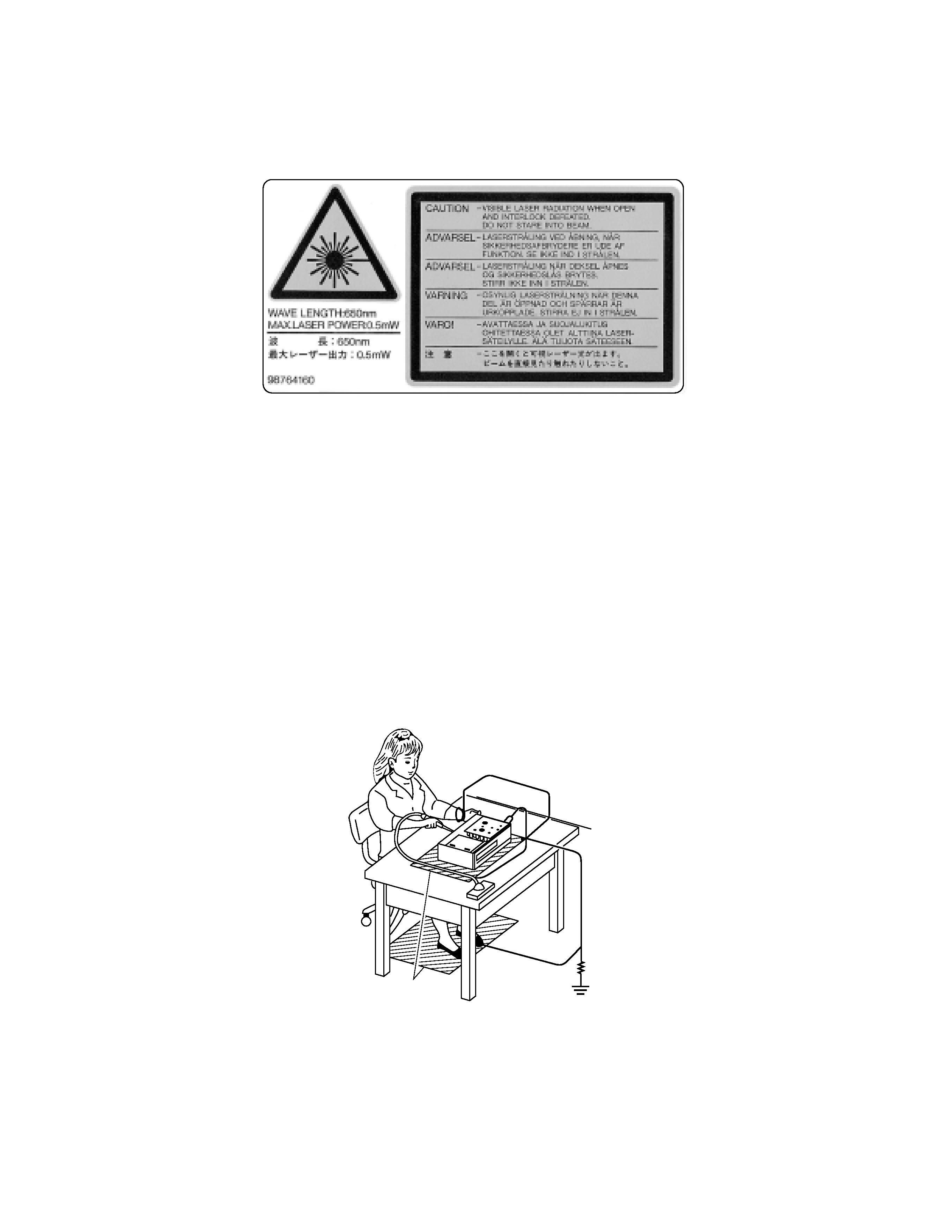
LASER BEAM CAUTION LABEL
When the power supply is being turned on, you may not remove this laser cautions label. If it removes, radiation of a laser
may be recceived.
PREPARATION OF SERVICING
Pickup Head consists of a laser diode that is very susceptible to external static electricity.
Although it operates properly after replacement, if it was subject to electrostatic discharge during replacement,
its life might be shortened. When replacing, use a conductive mat, soldering iron with ground wire, etc. to
protect the laser diode from damage by static electricity.
And also, the LSI and IC are same as above.
1M
Ground conductive
wrist strap for body.
Soldering iron
with ground wire
or ceramic type
Conductive mat
The ground resistance
between the ground line
and the ground is less than 10
.
SAFETY NOTICE
SAFETY PRECAUTIONS
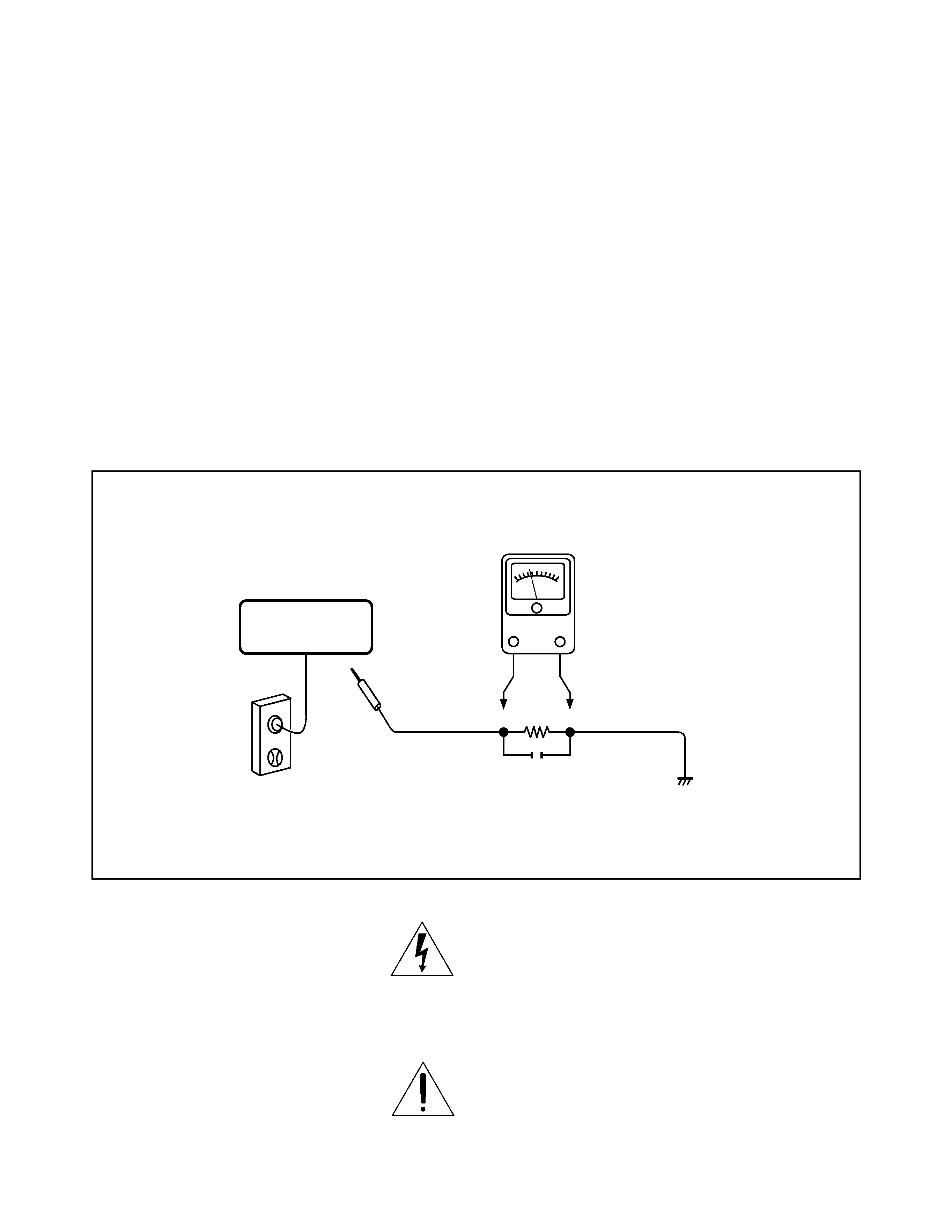
LEAKAGE CURRENT CHECK
Plug the AC line cord directly into a 120V AC outlet (do
not use an isolation transformer for this check). Use an
AC voltmeter, having 5000
per volt or more sensitivity.
Connect a 1500
10 W resistor, paralleled by a 0.15 µF
150V AC capacitor between a known good earth ground
(water pipe, conduit, etc.) and all exposed metal parts of
cabinet (antennas, handle bracket, metal cabinet
screwheads, metal overlays, control shafts, etc.).
Measure the AC voltage across the 1500
resistor.
The test must be conducted with the AC switch on and
then repeated with the AC switch off. The AC voltage
indicated by the meter may not exceed 0.3 V. A reading
exceeding 0.3 V indicates that a dangerous potential
exists, the fault must be located and corrected.
Repeat the above test with the DVD VIDEO PLAYER
power plug reversed.
NEVER RETURN A DVD VIDEO PLAYER TO THE
CUSTOMER WITHOUT TAKING NECESSARY
CORRECTIVE ACTION.
READING SHOULD NOT EXCEED 0.3V
The lightning flash with arrowhead symbol, within an
equilateral triangle, is intended to alert the user to the
presence of uninsulated "dangerous voltage" within the
product's enclosure that may be of sufficient magnitude to
constitute a risk of electric shock to persons.
The exclamation point within an equilateral triangle is
intended to alert the user to the presence of important
operating and maintenance (servicing) instructions in the
literature accompanying the appliance.
DVD VIDEO PLAYER
AC VOLTMETER
(5000
9 per volt
or more sensitivity)
Good earth ground
such as a water pipe,
conduit, etc.
1500
9
10 W
0.15
µF 150V AC
AC OUTLET
Test all exposed metal.
Voltmeter Hook-up for Leakage Current Check

SECTION 2
PART REPLACEMENT AND ADJUSTMENT PROCEDURES
SECTION 3
SERVICING DIAGRAMS
1. STANDING PC BOARDS FOR SERVICING
2. CIRCUIT SYMBOLS AND
SUPPLEMENTARY EXPLANATION
2-1. Precautions for Part Replacement
2-2. Solid Resistor Indication
2-3. Capacitance Indication
2-4. Inductor Indication
2-5. Waveform and Voltage Measurement
3. PRINTED WIRING BOARD AND
SCHEMATIC DIAGRAM
4. BLOCK DIAGRAMS
4-1. Overall Block Diagram
4-2. Power Supply Block Diagram
4-3. Front Display, Power Switch Block Diagram
4-4. Main Block Diagrams
4-5. Output Block Diagram
5. CIRCUIT DIAGRAMS
5-1. Power Supply Circuit Diagram
5-2. Front Display, Power Switch Circuit Diagram
5-3. Main Circuit Diagram
5-4. Output Circuit Diagram
5-5. Motor System Circuit Diagrams
6. PC BOARDS
6-1. Power Supply PC Board
6-2. Power Switch PC Board
6-3. Disc LED PC Board
6-4. Main PC Board
6-5. Output PC Board
6-6. Front Display PC Board
CONTENTS
SECTION 1
GENERAL DESCRIPTIONS
1. OPERATING INSTRUCTIONS
Specifications
2. LOCATION OF MAIN PARTS AND
MECHANISM PARTS
2-1. Location of Main Parts
2-2. Location of Mechanism Parts
1. REPLACEMENT OF MECHANICAL PARTS
1-1. Cabinet Replacement
1-1-1. Top Cover
1-1-2. Tray Panel
1-1-3. Front Panel
1-1-4. Rear Panel
1-2. PC Board Replacement
1-2-1. Main PC Board
1-2-2. Output PC Board
1-2-3. Power Supply PC board
1-2-4. Front Display and Power SW PC Boards
1-3. Mechanism Parts Replacement
1-3-1. Mechanism Chassis Assembly
1-3-2. Loading Belt
1-3-3. Loading Motor
1-3-4. Pickup Mechanism Assembly
1-3-5. Gear B Assembly, Gear A and
Rack Gear Assembly
1-3-6. Feed Motor
1-4. Tray Replacement
1-4-1. Tray Removal
1-4-2. Tray Mounting
3. TROUBLESHOOTING
3-1. Main Circuit
3-1-1. Servo System
3-1-2. Location Diagram of Servo Test Point
SECTION 4
PARTS LIST
SAFETY PRECAUTION
NOTICE
ABBREVIATIONS
1. Integrated Circuit (IC)
2. Capacitor (Cap)
3. Resistor (Res)
4. EXPLODED VIEWS
4-1. Packing Assembly
4-2. Chassis Assembly
4-3. Mechanism Assembly
5. PARTS LIST

SECTION 1
GENERAL DESCRIPTIONS
1. OPERATING INSTRUCTIONS
SECTION
1
GENERAL
DESCRIPTIONS