DVD VIDEO PLAYER
SERVICE MANUAL
Apr., 2001 5
FILE NO. 810-200013
SD-100X
D I G I TA L
V I D E O
Revised Edition
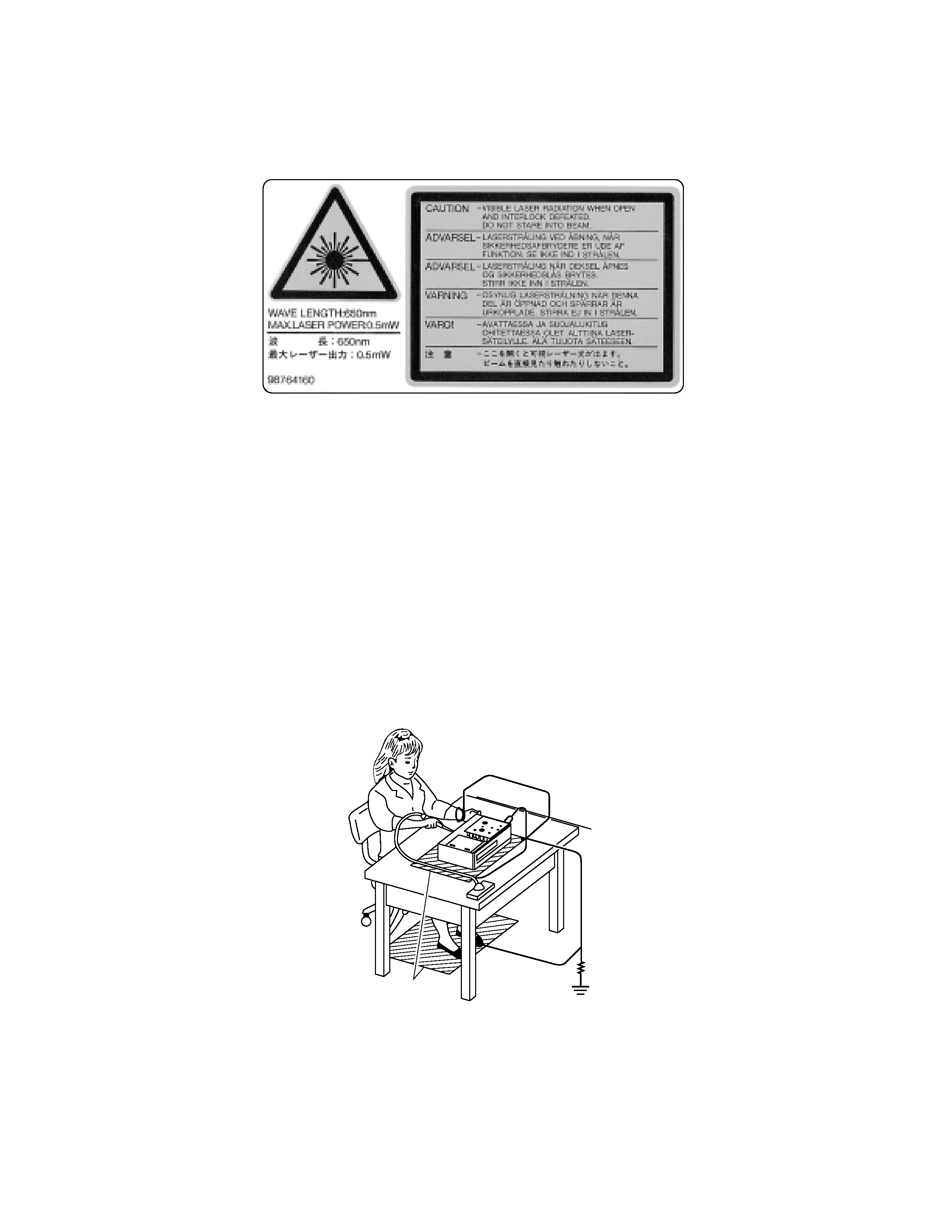
LASER BEA( CA*T,ON LABEL
When the power supply is being turned on, you may not remove this laser cautions label. If it removes, radiation of a laser
may be recceived.
PREPARAT,ON OF SER1,C,NG
Pi"#$p %e&d "onsists o' & (&ser diode t)&t is ver* s$s"epti+(e to e,tern&( st&ti" e(e"tri"it*.
A(t)o$-) it oper&tes proper(* &'ter rep(&"e.ent, i' it /&s s$+0e"t to e(e"trost&ti" dis")&r-e d$rin- rep(&"e.ent,
its (i'e .i-)t +e s)ortened. 1)en rep(&"in-, $se & "ond$"tive .&t, so(derin- iron /it) -ro$nd /ire, et". to
prote"t t)e (&ser diode 'ro. d&.&-e +* st&ti" e(e"tri"it*.
And &(so, t)e L34 &nd 4C &re s&.e &s &+ove.
1M9
Ground conductive
wrist strap for body.
Soldering iron
with ground wire
or ceramic type
Conductive mat
The ground resistance
between the ground line
and the ground is less than 109.

SECTION 2
PART REPLACEMENT AND ADJUSTMENT PROCEDURES
SECTION 3
SERVICING DIAGRAMS
1. STANDING PC BOARDS FOR SERVICING
2. CIRCUIT SYMBOLS AND
SUPPLEMENTARY EXPLANATION
2-1. Precautions for Part Replacement
2-2. Solid Resistor Indication
2-3. Capacitance Indication
2-4. Inductor Indication
2-5. Waveform and Voltage Measurement
2-6. Others
3. PRINTED WIRING BOARD AND
SCHEMATIC DIAGRAM
4. BLOCK DIAGRAMS
4-1. Overall Block Diagram
4-2. Power Supply Block Diagram
4-3. Front Display, Power Switch Block Diagram
4-4. Main Block Diagrams
4-5. Output Block Diagram
5. CIRCUIT DIAGRAMS
5-1. Power Supply Circuit Diagram
5-2. Front Display, Power Switch Circuit Diagram
5-3. Main Circuit Diagram
5-4. Output Circuit Diagram
5-5. Motor System Circuit Diagrams
6. PC BOARDS
6-1. Power Supply PC Board
6-2. Power Switch PC Board
6-3. Main PC Board
6-4. Output PC Board
6-5. Front Display PC Board
CONTENTS
SECTION 1
GENERAL DESCRIPTIONS
1. OPERATING INSTRUCTIONS
Specifications
2. LOCATION OF MAIN PARTS AND
MECHANISM PARTS
2-1. Location of Main Parts
2-2. Location of Mechanism Parts
1. REPLACEMENT OF MECHANICAL PARTS
1-1. Cabinet Replacement
1-1-1. Top Cover
1-1-2. Clamper Stay
1-1-3. Tray Panel
1-1-4. Front Panel and Tray
1-1-5. Rear Panel
1-2. PC Board Replacement
1-2-1. Main PC Board
1-2-2. Output PC Board
1-2-3. Power PC board
1-2-4. Front PC Board
1-3. Mechanism Parts
1-3-1. Mechanism Chassis Assembly
1-3-2. Loading Belt
1-3-3. Loading Motor
1-3-4. Sub Chassis (with a pickup mechanism)
1-3-5. Pickup Mechanism Assembly
1-3-6. Gear A Assembly, Gear B and
Rack Gear Assembly
1-3-7. Feed Motor
3. TROUBLESHOOTING
3-1. Main Circuit
3-1-1. Servo System
3-1-2. Location Diagram of Servo Test Point
SECTION 4
PARTS LIST
SAFETY PRECAUTION
NOTICE
ABBREVIATIONS
1. Integrated Circuit (IC)
2. Capacitor (Cap)
3. Resistor (Res)
4. EXPLODED VIEWS
4-1. Packing Assembly
4-2. Chassis Assembly
4-3. Mechanism Assembly
5. PARTS LIST
Note:
The power supply circuit is available in two types and their usage
differs depending on parts, Q826 and Q827.
For maintenance services, when replacing Q826 and/or Q827, use
new parts of their same corresponding type.
When replacing a power supply unit, only Type A parts will be
supplied.

SECTION 1
GENERAL DESCRIPTIONS
1. OPERATING INSTRUCTIONS
SECTION
1
GENERAL
DESCRIPTIONS
2
Introduction
SAFETY PRECAUTIONS
WARNING:
TO REDUCE THE RISK OF FIRE OR ELECTRIC SHOCK, DO NOT EXPOSE THIS APPLIANCE
TO RAIN OR MOISTURE. DANGEROUS HIGH VOLTAGES ARE PRESENT INSIDE THE
ENCLOSURE. DO NOT OPEN THE CABINET. REFER SERVICING TO QUALIFIED PERSONNEL
ONLY.
CAUTION:
TO PREVENT ELECTRIC SHOCK, MATCH WIDE BLADE OF PLUG TO WIDE SLOT, FULLY
INSERT.
ATTENTION:
POUR EVITER LES CHOCS ELECTRIQUES, INTRODUIRE LA LAME LA PLUS LARGE DE LA
FICHE DANS LA BORNE CORRESPONDANTE DE LA PRISE ET POUSSER JUSQU'AU FOND.
CAUTION:
This Digital Video Disc Player employs a Laser System.
To ensure proper use of this product, please read this owner's manual carefully and retain for
future reference. Should the unit require maintenance, contact an authorized service location -
see service procedure.
Use of controls or adjustments or performance of procedures other than those specified herein
may result in hazardous radiation exposure.
To prevent direct exposure to laser beam, do not try to open the enclosure.
Visible laser radiation when open and interlocks defeated.
DO NOT STARE INTO BEAM.
FCC NOTICE: This equipment has been tested and found to comply with the limits for a Class B digital device,
pursuant to part 15 of the FCC Rule. These limits are designed to provide reasonable protection
against harmful interference in a residential installation.
This equipment generates, uses, and can radiate radio frequency energy and, if not installed
and used in accordance with the instructions, may cause harmful interference to radio
communications.
However, there is no guarantee that interference will not occur in a particular installation.
If this equipment does cause harmful interference to radio or television reception, which can be
determined by turning the equipment off and on, the user is encouraged to try to correct the
interference by one or more of the following measures:
- Reorient or relocate the receiving antenna.
- Increase the separation between the equipment and receiver.
- Connect the equipment into an outlet on a circuit different from that to which the receiver is
connected.
- Consult the dealer or an experienced radio/TV technician for help.
WARNING:
Changes or modifications made to this equipment, not expressly approved by Toshiba, or parties
authorized by Toshiba, could void the user's authority to operate the equipment.
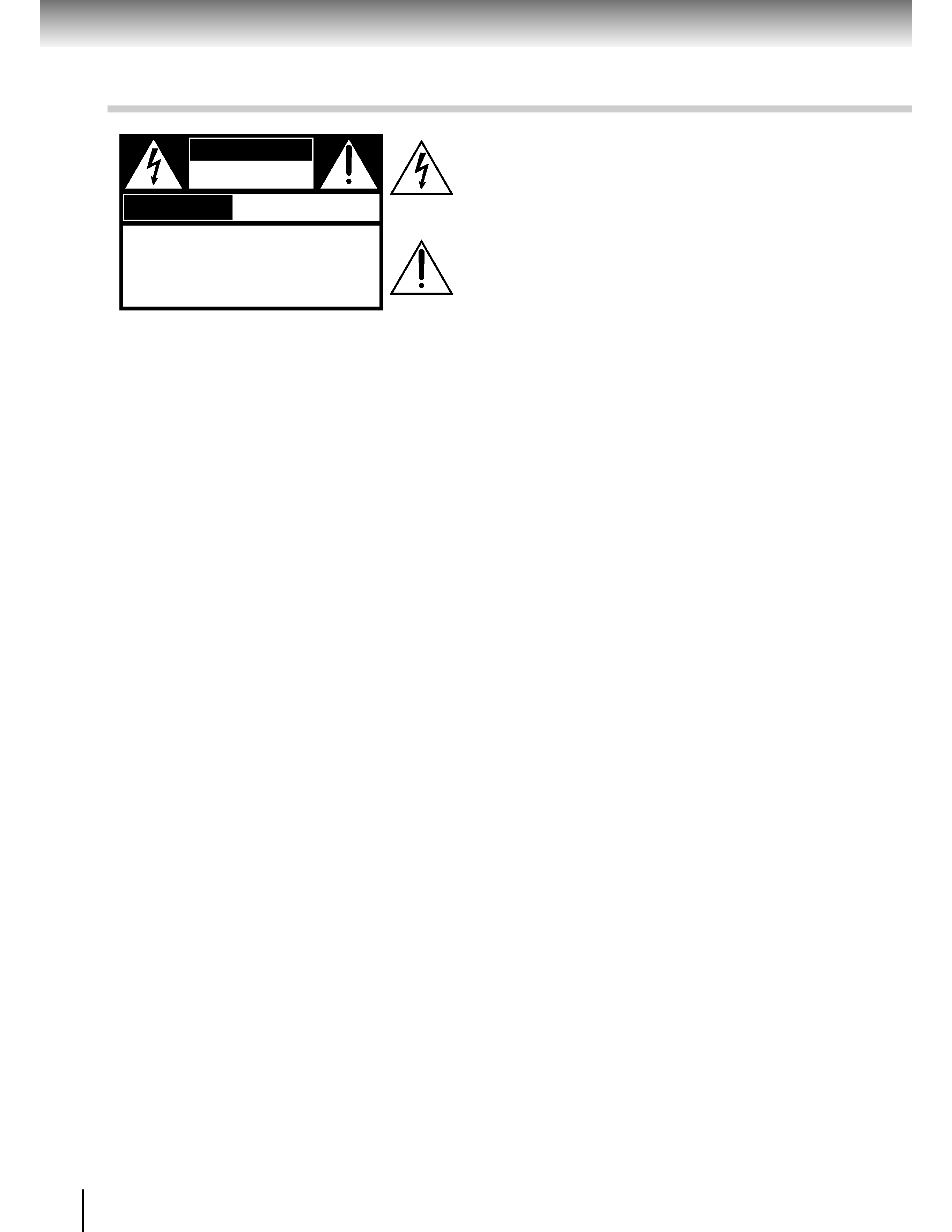
The lightning flash with arrowhead symbol, within an equilat-
eral triangle, is intended to alert the user to the presence of
uninsulated "dangerous voltage" within the product's enclo-
sure that may be of sufficient magnitude to constitute a risk
of electric shock to persons.
The exclamation point within an equilateral triangle is in-
tended to alert the user to the presence of important operat-
ing and maintenance (servicing) instructions in the literature
accompanying the appliance.
WARNING
RISK OF ELECTRIC SHOCK
DO NOT OPEN
AVIS
RISQUE DE CHOC ELECTRIQUE NE
PAS OUVRIR
WARNING :
TO REDUCE THE RISK OF
ELECTRIC SHOCK,
DO NOT REMOVE
COVER (OR BACK). NO USERSERVICEABLE
PARTS INSIDE.
REFER SERVICING TO
QUALIFIED SERVICE PERSONNEL.