DIGITAL STILL CAMERA
SERVICE MANUAL
PDR-M60
PRINTED IN JAPAN, Mar., 2001 5
PDR-M60
FILE NO. 210-200101

CONTENTS
1. DISASSEMBLING PROCEDURES ................................................................................... 1
1-1. Disassembling Procedures .................................................................................................................. 1
1-2. Notes on Assembling and Disassembling ......................................................................................... 1
2. OUTLINE OF ELECTRICAL CIRCUIT .............................................................................. 2
2-1. System Over View ................................................................................................................................. 2
2-2. Boot up Sequence ................................................................................................................................ 5
2-3. OFF Mode .............................................................................................................................................. 5
2-4. Image Capturing .................................................................................................................................... 5
2-5. LCD ......................................................................................................................................................... 6
2-6 Monitor Out ............................................................................................................................................ 6
2-7. Lens Control .......................................................................................................................................... 6
2-8. AF&AE .................................................................................................................................................... 6
2-9. Zoom ...................................................................................................................................................... 6
2-10. Card Access ....................................................................................................................................... 6
2-11. Strobe Control .................................................................................................................................... 6
2-12. Power Supply ..................................................................................................................................... 6
2-13. Alignment Data................................................................................................................................... 6
3. ELECTRICAL ADJUSTMENT ........................................................................................... 7
4. CIRCUIT DIAGRAM ........................................................................................................ 16
4-1. Logic Unit Circuit Diagram................................................................................................................. 16
4-2. Power Unit Circuit Diagram ............................................................................................................... 18
4-3. Microprocessor Unit Circuit Diagram ............................................................................................... 20
4-4. Lens Unit Circuit Diagram .................................................................................................................. 22
4-5. Switch Unit Circuit Diagram .............................................................................................................. 23
5. CHASSIS ASSEMBLY .................................................................................................... 24
6. PARTS LIST ....................................................................................................................25

1. DISASSEMBLING PROCEDURES
1-1. Disassembling Procedures
1. Remove the battery and the SmartMedia.
2. Remove five screws and two tripod fixing screws.
Open the DC jack cover and remove the rear cover
pushing the DC jack to the front.
3. Remove the FPC located on the switch PC board,
remove one screw of the wiring fixed to the rear
cover and peel off the adhesive tape.
4. Front Cover Parts Removal
1) Remove the color LCD block from the lens
backside.
Peel off the adhesive tape fixing the color LCD
block and remove one fixing screw of lens after
separating the block from the lens.
2) Remove the unit block from the front cover.
5. Unit Block Disassembling Procedures
1) Disconnect the microprocessor PC board from
the logic PC board.
2) Disconnect the lens PC board from the logic PC
board.
3) Remove the lens FPC from the logic PC board.
4) Remove two screws fixed to the carriage to
separate the lens block.
5) Remove two fixing screws of logic PC board
fixed to the carriage.
6) Disconnect the logic PC board from power PC
board.
7) Remove the wiring of the color LCD block to
separate it from the unit block.
Disconnect two FPCs on the logic PC board and
disconnect the power PC board.
8) Remove three screws fixed to the carriage.
Remove the strobe from the carriage.
6. Removal of REAR-COVER part
1) Remove the FPC for the mode dial from the
switch PC board.
2) Remove two fixing screws of switch PC board to
separate the switch PC board. Do not damage
the button when removing the fixing screws.
3) Remove two fixing screws for the mode dial to
separate the mode dial.
1-2. Notes on Assembling and Disas-
sembling
1. Be sure to discharge the condenser of strobe to
prevent electric shock.
2. Note the breaking of wires because a lot of connec-
tions are done by FPC and wirings.
3. Some parts and wirings are protected with adhe-
sive tapes. So, when peeling off the adhesive
tape(s), do it carefully.
1

2. OUTLINE OF ELECTRICAL CIR-
CUIT
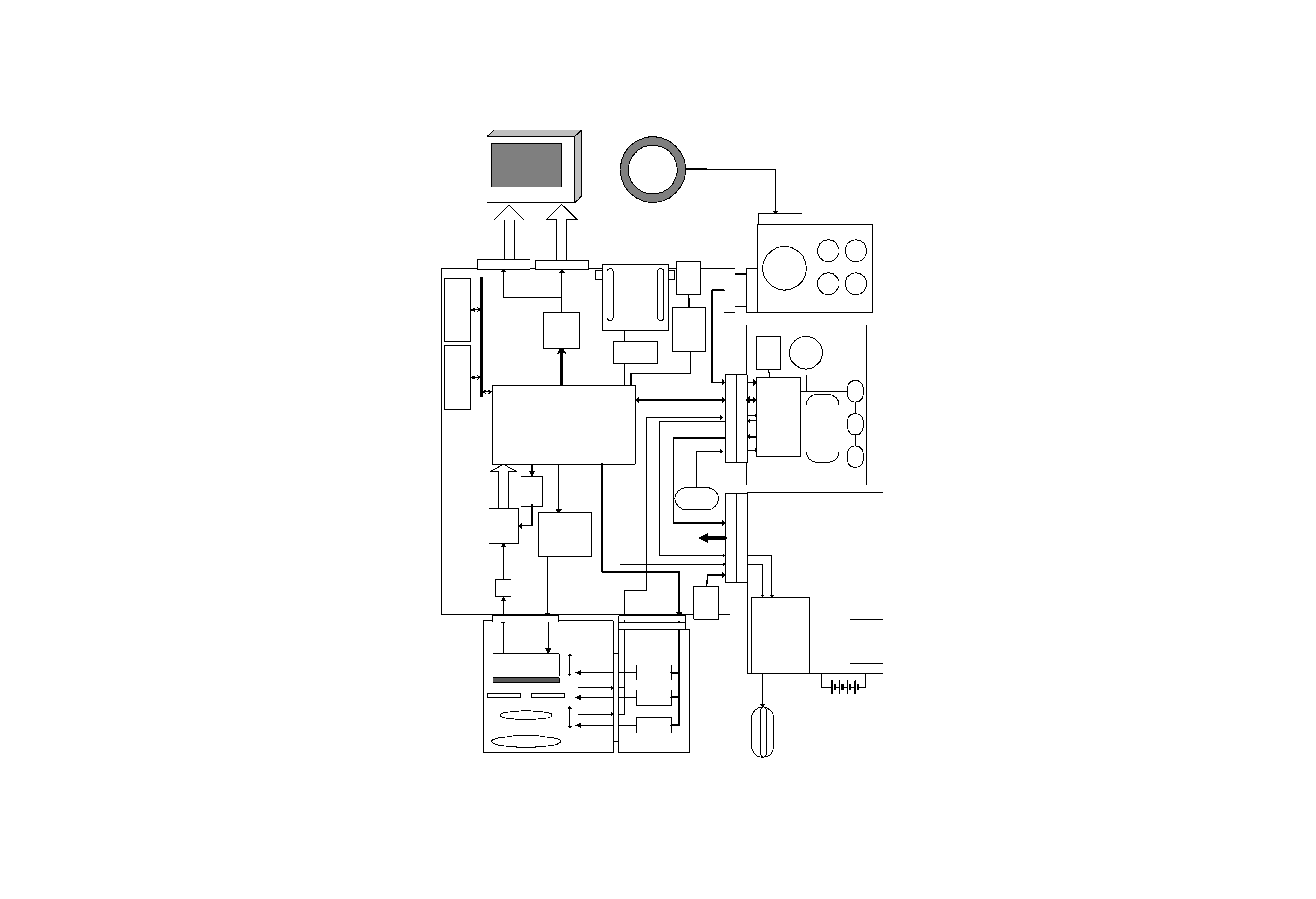
2-1. System Over View
It consists of 5 PC boards, lens module, color LCD and
mode dial.
Microprocessor unit detects the power management
and key operation and functions as a slave microproc-
essor of DSP (Raptor) in the Logic unit. Logic unit
covers all functions of signal processing and camera
functions.
2
U100
Logic Unit
OS
Color LCD
Drive
Drive
Drive
U2
FLASH RAM
(M29W400BT90)
U21
SD RAM
(HY57V651620)
CDS/AD
U24
LCD_Data
Q38
TR
V&HDriver
PU1,PU2
U25B
U20
DSP
(MB87J33020)
U25A
Buffer
U3
LCD Drv
(EM1812B)
I_Data(10bit)
J3
USB CNT
U1
USB Driver
USB6B1
U26,27
BusBuffer
J15
SM socket
CN015P-2103-1
SW11,12
Zoom
Key
CCD control
J4A
CCD
Zoom
Focus
Iris
IR filter
Sence
OS
Sence
H001
Lens Module
U400
Lens Unit
U401
LB1848M
U402
LB1848M
U403
LB1848M
J0402
J18
J19
J14
J2A
J1A
A240
Mode Dial
U500
Switch
J10
U200
MPU Unit
U23
MPU
(MB89P165PFV-G-255)
U301
Reset
SW304
Shutter
BW LCD
U300
Power Unit
Strobe
J23
J502
FPC
J201A
J401A
Flash
UIO_SDATA,SDIR,TIMER_INT
FLASH_ENb
FLASH
DC_IN
POWER_EN,BACK_CUR,etc
SW301,302,303
2.5V
3.3V
3.3V_UC
5V
6V
15V
J501
Video Buffer
3
4