DIGITAL STILL CAMERA
SERVICE MANUAL
PDR-M25
CREATED IN JAPAN, Nov., 2001
PDR-M25
FILE No. 210 - 200107
TOSHIBA PDR-M25
Service Manual
Topics
Description
Pages
1.
System Overview
Camera system introduction
2-5
Operation Steps of Disassembly
6-8
2.
Disassembly /Assembly
Operation Steps of Assembly
10-12
3.
Calibration
Camera Calibration
13-18
4.
Troubleshooting
19
5.
Service Parts
Explode Diagram
Screw List
20
21
6.
Packing Parts
Packing Explode Diagram
Part List for Packing Accessory
22
23
Updated : Dec. 08 2001
Prepared by Premier Image Technology Corp.
2
Section
1. System Overview

3
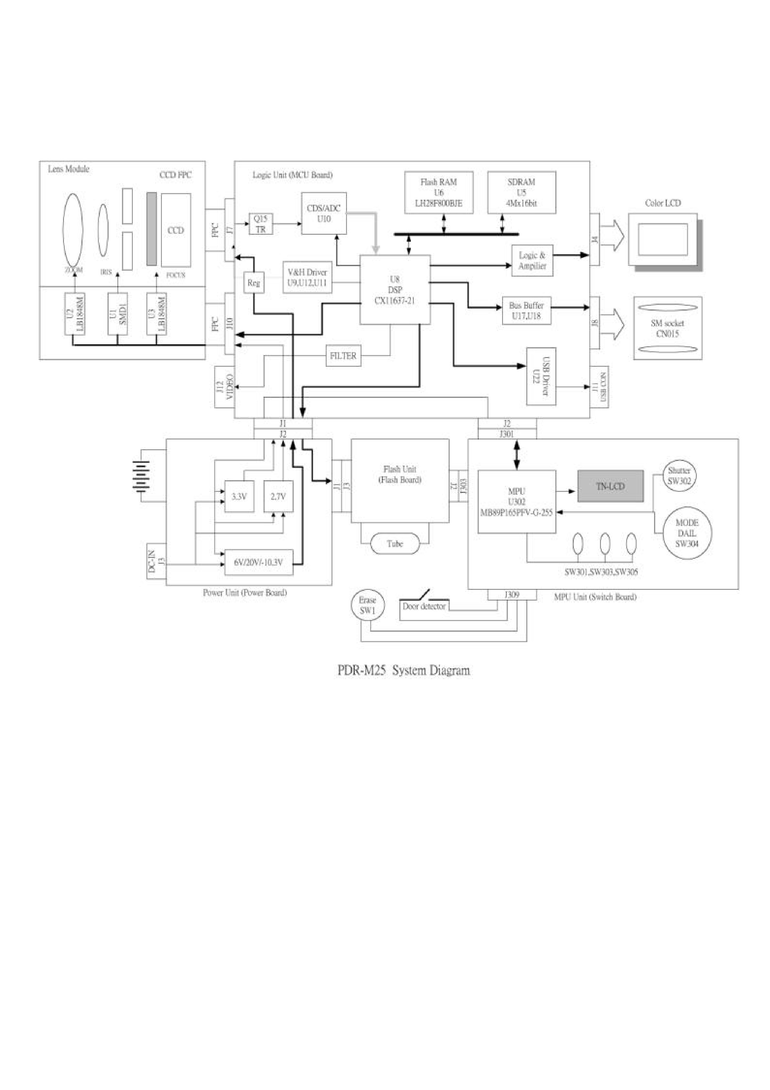
1-1 System Overview
It consists of 4 PC boards, lens module, color LCD and Smart Media Connector etc.
Microprocessor unit detects the power management and key operation and functions as a slave microprocessor of DSP(Raptor ) in
the Logic unit. Logic unit covers all function of signal processing and camera functions.
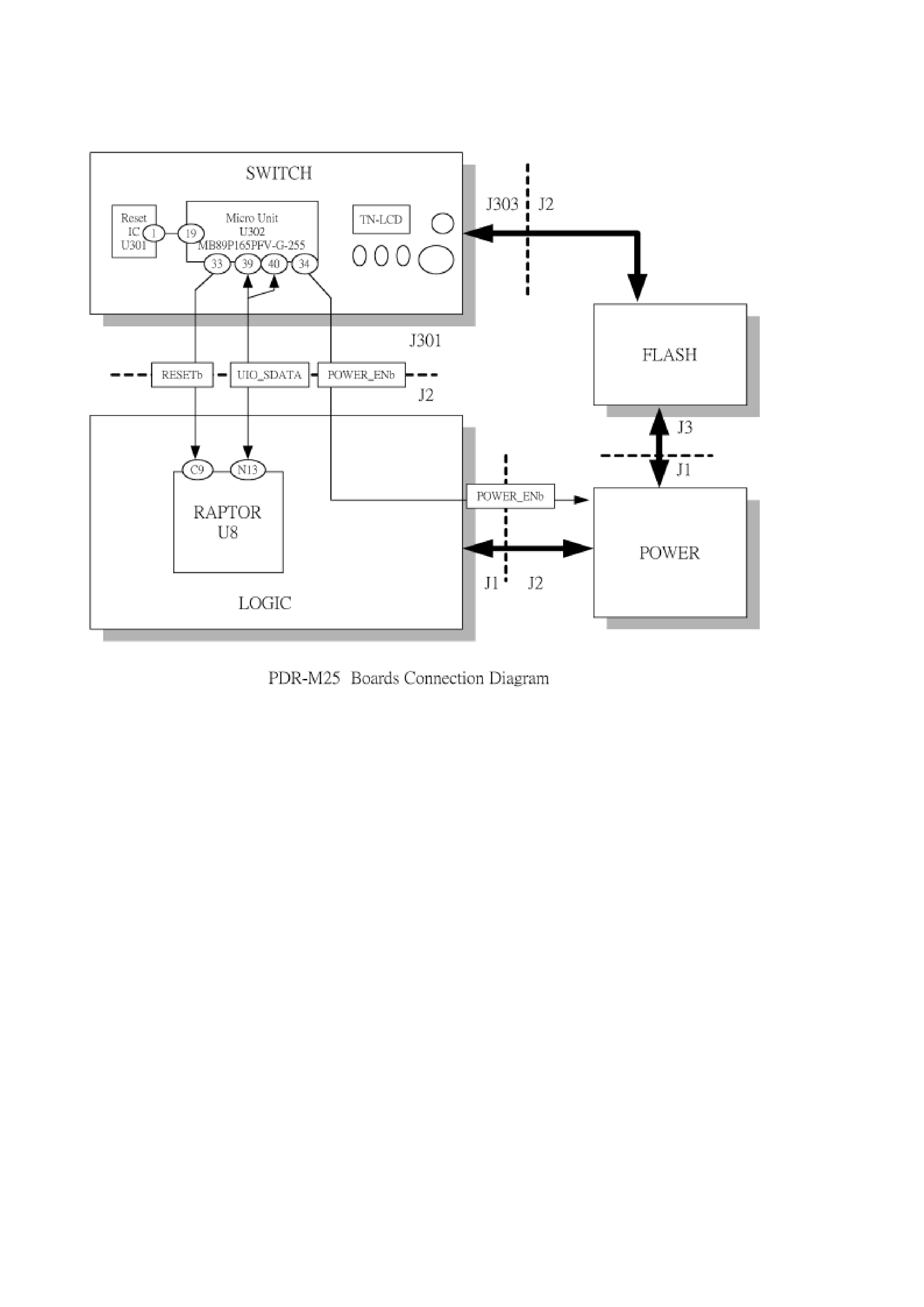
1-2 Boot up Sequence
The voltage of 3.3V_UC is supplied by a battery insertion or DC input. The microprocessor (U302) is reset and starts the boot-up
operation of DSP (logic board - U8 ). Also, the microprocessor performs the boot-up operation of DSP when detecting DC JACK of
battery insertion/extraction. The boot-up procedures are as follows:
1.The microprocessor asserts the POWER_ENb signal (switch board - U302 pin34) to LOW and turns the power on.
2.The microprocessor(switch board - U302) sends a reset signal to the microprocessor DSP ( U8 ) and checks whether the status
signal from UIO_SDATA is returned. When the normal signal does not return, the reset signal is sent again. The microprocessor
starts Key scan. DSP starts to perform the designated processes after receiving the mode information from the microprocessor.
1-3 OFF Mode
When Pin26 (SW board - J301)POWER_SW signal (SW board-U302,Pin24) of the ON/OFF switch (Logic board - J1,Sw2) asserts
signal to high, the microprocessor enters OFF mode.
In this case, the microprocessor turns all the power off and performs Key scan by every 250 ms. After 10 seconds of entering the
OFF mode, the microprocessor enters the power saving mode (Deep sleep mode) and all functions except for the Timer are set to
OFF. When sliding the POWER knob to turn on the power again, the microprocessor restarts.
1-4 Image Capturing
The CCD driving signal (TG) is generated by the programmable timing generator (PTG)in DSP(Logic board -U8), which is
converted into appropriate voltage to drive the CCD through buffers(U17,U18). The output from the lens module enters the logic
board through connector J10. The OS output is A/D-converted in CDS through TR(Q15) and then entered DSP(U8). The color
separation is carried out inside the DSP and the processed signal(data)is stored inside the SDRAM(U5) .
1-5 LCD
After the images stored on the SDRAM(logic board - U5) are processed inside DSP (U8) again, they are modified to the appropriate
size, bit width(6bit per each RGB) and sent to the LCD driver with the driving signal required.
1-6 Monitor Out
In the same way as described in the LCD section after the images are modified to the appropriate size, the Video player(VP)inside U8
develops a signal modulated to NTSC and PAL format by DA output(pin K14) of U8.The image signal passes through the 75ohm
driver circuit inside the logic unit and develops from the connector(J12)
1-7 Lens Control
The lens module controls the step motor control signal(Logic board - J10)input for Zoom, Focus and Iris & shutter, the focus position
switch output(J10,pin1)for the focus position detection and the potentiometer output(J10,pin4)for the zoom position detection Each
motor control signal is converted to 2-sphase excitation signal in the motor driver by using the PWM output (J10, pin14, pin15)of
DSP and sent to the motor.
4
1-8 AF & AE
The captured images are processed by shifting the iris and focus position inside DSP(U8)to obtain the best iris & focus position.
Only when using a half-shutter function, AE&AF operation is carried out.
1-9 Zoom
Zoom key -> detection of potentiometer alignment by a sub-microprocessor -> Raptor PWM output -> Control by a motor. The fine
adjustment of focus is carried out by every position at Zoom.
1-10 Card Access
The data stored on a SDRAM(logic board U5) is compressed inside DSP(U8) and recorded in a SM card . The Gate (logic board -
U17,U18) is inserted to protect for a damage by insertion /extraction of a card. The gate is forcedly opened /closed by a card
detection signal (logic board , J8 pin12)of socket the presence or absence of the card is detected according to the detection of the door
opened/closed signal .
1-11 Strobe Control
Strobe charge is controlled by a sub microprocessor (switch board, U302) and the light emission is controlled by DSP (U8)
corresponding to the CCD output amount. The sub microprocessor detects a charge voltage by turning STROBE_V(switch board ,