SERVICE MANUAL
COLOR TELEVISION/
VIDEO CASSETTE
RECORDER
MV13N2
FILE NO. 140-200213
DOCUMENT CREATED IN JAPAN, Dec., 2002
SERVICING NOTICES ON CHECKING
6. AVOID AN X-RAY
1. KEEP THE NOTICES
As for the places which need special attentions,
they are indicated with the labels or seals on the
cabinet, chassis and parts. Make sure to keep the
indications and notices in the operation manual.
3. USE THE DESIGNATED PARTS
5. TAKE CARE TO DEAL WITH THE
CATHODE-RAY TUBE
In the condition that an explosion-proof cathode-
ray tube is set in this equipment, safety is
secured against implosion. However, when
removing it or serving from backward, it is
dangerous to give a shock. Take enough care to
deal with it.
Safety is secured against an X-ray by consider-
ing about the cathode-ray tube and the high
voltage peripheral circuit, etc.
Therefore, when repairing the high voltage pe-
ripheral circuit, use the designated parts and
make sure not modify the circuit.
Repairing except indicates causes rising of high
voltage, and it emits an X-ray from the cathode-
ray tube.
Please include the following informations when you order parts. (Particularly the VERSION LETTER.)
1. MODEL NUMBER and VERSION LETTER
The MODEL NUMBER can be found on the back of each product and the VERSION LETTER can be
found at the end of the SERIAL NUMBER.
2. PART NO. and DESCRIPTION
You can find it in your SERVICE MANUAL.
HOW TO ORDER PARTS
PERFORM A SAFETY CHECK AFTER
SERVICING
7.
Confirm that the screws, parts and wiring which
were removed in order to service are put in the
original positions, or whether there are the
portions which are deteriorated around the
serviced places serviced or not. Check the
insulation between the antenna terminal or
external metal and the AC cord plug blades.
And be sure the safety of that.
(INSULATION CHECK PROCEDURE)
1.
2.
3.
4.
Unplug the plug from the AC outlet.
Remove the antenna terminal on TV and turn
on the TV.
Insulation resistance between the cord plug
terminals and the eternal exposure metal
[Note 2] should be more than 1M ohm by
using the 500V insulation resistance meter
[Note 1].
If the insulation resistance is less than 1M
ohm, the inspection repair should be
required.
[Note 1]
If you have not the 500V insulation
resistance meter, use a Tester.
[Note 2]
External exposure metal: Antenna terminal
2. AVOID AN ELECTRIC SHOCK
There is a high voltage part inside. Avoid an
electric shock while the electric current is
flowing.
The parts in this equipment have the specific
characters of incombustibility and withstand
voltage for safety. Therefore, the part which is
replaced should be used the part which has
the same character.
Especially as to the important parts for safety
which is indicated in the circuit diagram or the
table of parts as a
mark, the designated
parts must be used.
4. PUT PARTS AND WIRES IN THE
ORIGINAL POSITION AFTER
ASSEMBLING OR WIRING
There are parts which use the insulation
material such as a tube or tape for safety, or
which are assembled in the condition that
these do not contact with the printed board.
The inside wiring is designed not to get closer
to the pyrogenic parts and high voltage parts.
Therefore, put these parts in the original
positions.
A1-1

TABLE OF CONTENTS
SERVICING NOTICES ON CHECKING .....................................................................................
HOW TO ORDER PARTS ..........................................................................................................
TABLE OF CONTENTS ..............................................................................................................
GENERAL SPECIFICATIONS ...................................................................................................
DISASSEMBLY INSTRUCTIONS
1. REMOVAL OF MECHANICAL PARTS AND P. C. BOARDS ............................................
2. REMOVAL OF VCR DECK PARTS ...................................................................................
3. REMOVAL OF ANODE CAP ..............................................................................................
4. REMOVAL AND INSTALLATION OF FLAT PACKAGE IC ...............................................
KEY TO ABBREVIATIONS ........................................................................................................
SERVICE MODE LIST ................................................................................................................
PREVENTIVE CHECKS AND SERVICE INTERVALS ..............................................................
WHEN REPLACING EEPROM (MEMORY) IC ..........................................................................
SERVICING FIXTURES AND TOOLS .......................................................................................
PREPARATION FOR SERVICING .............................................................................................
MECHANICAL ADJUSTMENTS ................................................................................................
ELECTRICAL ADJUSTMENTS ..................................................................................................
BLOCK DIAGRAMS
TV ............................................................................................................................................
Y/C/AUDIO/HEAD AMP ..........................................................................................................
MICON/IN/OUT/AV .................................................................................................................
PRINTED CIRCUIT BOARDS
SYSCON/CRT .........................................................................................................................
SCHEMATIC DIAGRAMS
Y/C/AUDIO/HEAD AMP ..........................................................................................................
MICON .....................................................................................................................................
IN/OUT .....................................................................................................................................
AV ............................................................................................................................................
CHROMA/IF .............................................................................................................................
SOUND AMP ...........................................................................................................................
TV POWER .............................................................................................................................
DEFLECTION ..........................................................................................................................
CRT ..........................................................................................................................................
INTERCONNECTION DIAGRAM ...............................................................................................
WAVEFORMS .............................................................................................................................
MECHANICAL EXPLODED VIEWS ...........................................................................................
CHASSIS EXPLODED VIEWS ...................................................................................................
MECHANICAL REPLACEMENT PARTS LIST .........................................................................
CHASSIS REPLACEMENT PARTS LIST ..................................................................................
ELECTRICAL REPLACEMENT PARTS LIST ...........................................................................
A1-1
A1-1
A2-1
A3-1~A3-5
B1-1
B2-1~B2-6
B3-1
B4-1, B4-2
C1-1, C1-2
C2-1
C3-1, C3-2
C4-1
D1-1
D1-1
D2-1~D2-4
D3-1~D3-6
E-1, E-2
E-3, E-4
E-5, E-6
F-1~F-4
G-1, G-2
G-3, G-4
G-5, G-6
G-7, G-8
G-9, G-10
G-11, G-12
G-13, G-14
G-15, G-16
G-17, G-18
G-19, G-20
H-1, H-2
I1-1, I1-2
I2-1, I2-2
J1-1
J2-1
J3-1~J3-4
A2-1
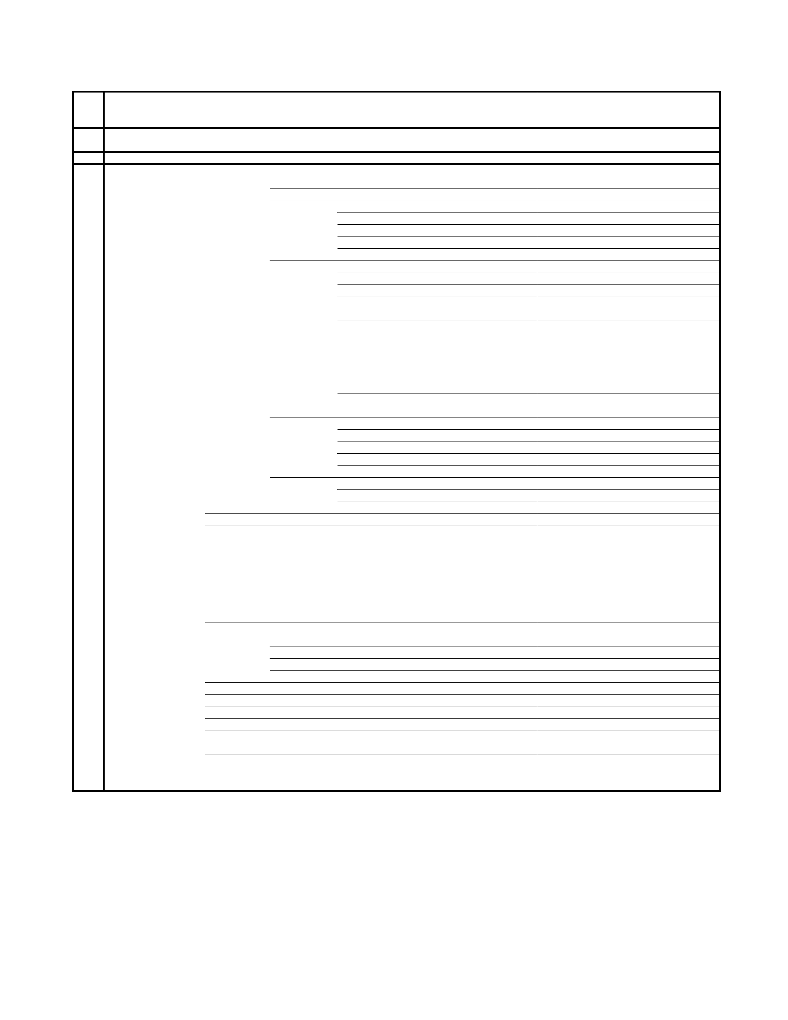
GENERAL SPECIFICATIONS
G-1
TV
CRT
CRT Size / Visual Size
13 inch / 335.4mmV
System
CRT Type
Normal
Deflection
90
degree
Magnetic Field
BV/BH
+0.45G / 0.18G
Color System
NTSC
Speaker
1Speaker
Position
Front
Size
1.5
x 2.5 Inch
Impedance
8
ohm
Sound Output
MAX
1.5
W
10%(Typical)
1.0
W
G-2
VCR
System
VHS Player / Recorder
System
Video System
NTSC
Hi-Fi STEREO
No
NTSC PB
-
Deck
DECK
OVD-7
Loading System
Front
Motor
3
Heads
Video Head
2 Head
FM Audio Head
No
Audio /Control
Mono/Yes
Erase(Full Track Erase)
Yes
Tape
Rec
PAL
-
Speed
NTSC
SP/SLP
Play
PAL
-
NTSC
SP/SLP
Fast Forward / Rewind Time (Approx.) at 25oC
FF:4'50"/REW:2'30"
with Cassette
T-120
Forward/Reverse
NTSC or PAL-M
SP/SLP=3x,5x/9x,15x
Picture Search
PAL or SECAM
-
Frame Advance
-
Slow Speed
-
G-3
Tuning
Broadcasting System
US System M
System
Tuner and
System
1Tuner
Receive CH
Destination
US(w/CATV)
Tuning System
F-Synth
Input Impedance
VHF/UHF 75 ohm
CH Coverage
2~69, 4A,A-5~A-1, A~I,
J~W,W+1~W+84
Intermediate
Picture(FP)
45.75MHz
Frequency
Sound(FS)
41.25MHz
FP-FS
4.5MHz
Preset CH
No
Stereo/Dual TV Sound
No
Tuner Sound Muting
Yes
G-4
Signal
Video Signal
Input Level
1 V p-p/75 ohm
Output Level
-
S/N Ratio (Weighted)
50dB
Horizontal Resolution at SP Mode
220Lines
Audio Signal
Input Level
-8dBm/50k ohm
Output Level
-
S/N Ratio at SP (Weighted)
38dB
Harmonic Distortion at SP (1KHz)
Typical
1.5
%
Frequency Response
at SP
100Hz - 10kHz
at LP
-
at SLP
100Hz - 4kHz
Hi-Fi Audio Signal
Dynamic Range : More than
-
Frequency Response
-
Wow And Flutter : Less than
-
Channel Separation : More than
-
Harmonic Distortion : Less than
-
G-5
Power
Power Source
AC
120V 60Hz
DC
-
Power Consumption
at AC
65 W at 120V 60Hz
at DC
-
Stand by (at AC)
5 W at 120V 60 Hz
Per Year
-
Protector
Power Fuse
Yes
Dew Sensor
No
A3-1
GENERAL SPECIFICATIONS
G-6
Regulation
Safety
UL
Radiation
FCC
X-Radiation
DHHS
G-7
Temperature
Operation
+5oC ~ +40oC
Storage
-20oC ~ +60oC
G-8
Operating Humidity
Less than 80% RH
G-9
On Screen
Menu
Yes
Display
Menu
Type
Character
Timer Rec Set
Yes
Channel Setup
Yes
TV/CATV
Yes
Auto CH Memory
Yes
Add/ Delete
Yes
Guide CH Set
No
TV Setup
Yes
V-chip Set
Yes
On/Off Timer Set
Yes
Picture
Yes
Audio
No
Sap On/Off
No
Auto Repeat On/Off
Yes
System Setup
Yes
Clock Set
Yes
Language
Yes
Auto Clock On/Off
Yes
Standard Time
Yes
Daylight Saving Time
Yes
Commercial Advance
No
Marking On/Off
No
Blueback On/Off
No
Playback Auto/Manual
No
Unmarked Tape
No
Movie Advance
No
Go To Movie
No
Go To Preview
No
G-CODE(or SHOWVIEW or PLUSCODE)No. Entry
No
Clock
Yes
CH/AV
Yes
Tape Counter(Linear Counter)
Yes
Tape Speed
Yes
Sleep Time
Yes
Stereo/Audio Output
No
Bilingual
No
SAP
No
Control
Volume
Yes
Level
Bright / Contrast / Sharpness / Color
Yes
Tint
Yes
Bass/Treble/Balance
No
Manual Tracking
Yes
Play/Stop/FF/Rew/Rec/OTR/T-Rec/Pause/Eject/Tape In
(Symbol Mark)
Yes
Auto Tracking/Manual Tracking
Yes
Caption / Text
Yes
Index
No
Mute
Yes
Hi-Fi
No
Repeat
Yes
Zero Return
Yes
DEW
No
A3-2