TOSHIBA
FILE NO. 120-9601
RDER
M-672, M-672C
M-65, M-65C
PRINTED IN KOREA, MAY, 1996
2. DISASSEMBLY & REASSEMBLY
2-1. INSTRUMENT DISASSEMBLY
2-l-l. Bottom Cover Removal
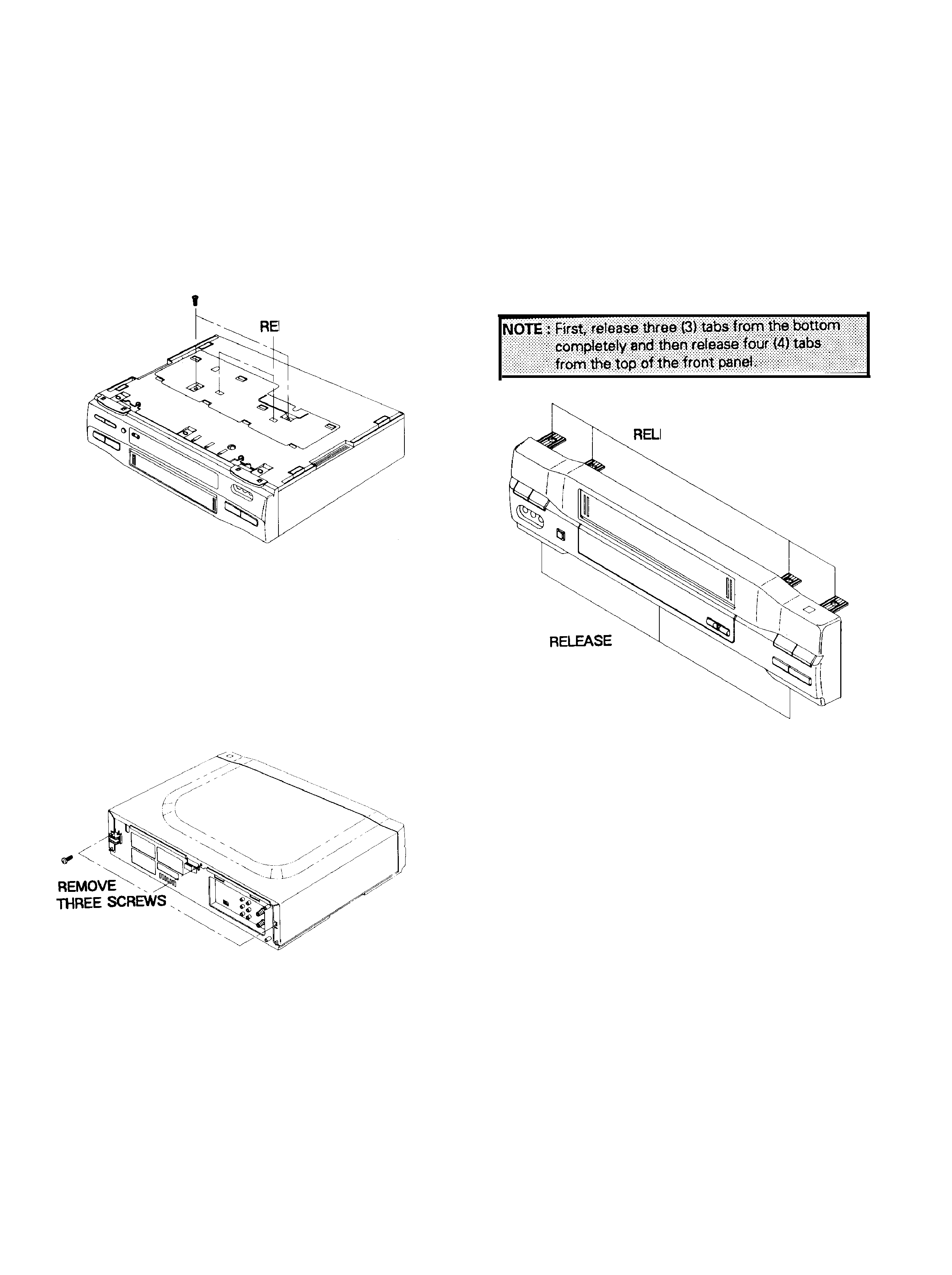
1. Remove two (2) screws holding the bottom cover.
2. Release two (2) tabs from the bottom cover.
REMOVE TWO SCREWS
LEASE TWO TABS
Fig. 1 Bottom Cover Removal
2-l-2.Top Cabinet Removal
1. Remove three(3)screws located at the rear of the top
cabinet.
2. Carefully lift the back of the top cabinet and slide it to
the rear to remove.
2-l-3. Front Panel Removal
1. Remove bottom cover and top cabinet (See Fig. 1 to
2).
2. Release three (3) tabs from the bottom of the front
panel.
3. Release four (4) tabs from the top of the front panel.
4. Tilt the front panel forward to remove.
EASE FOUR TABS
THREE TABS
Fig. 3 Front Panel Removal
Fig. 2 Top Cover Removal
2-1
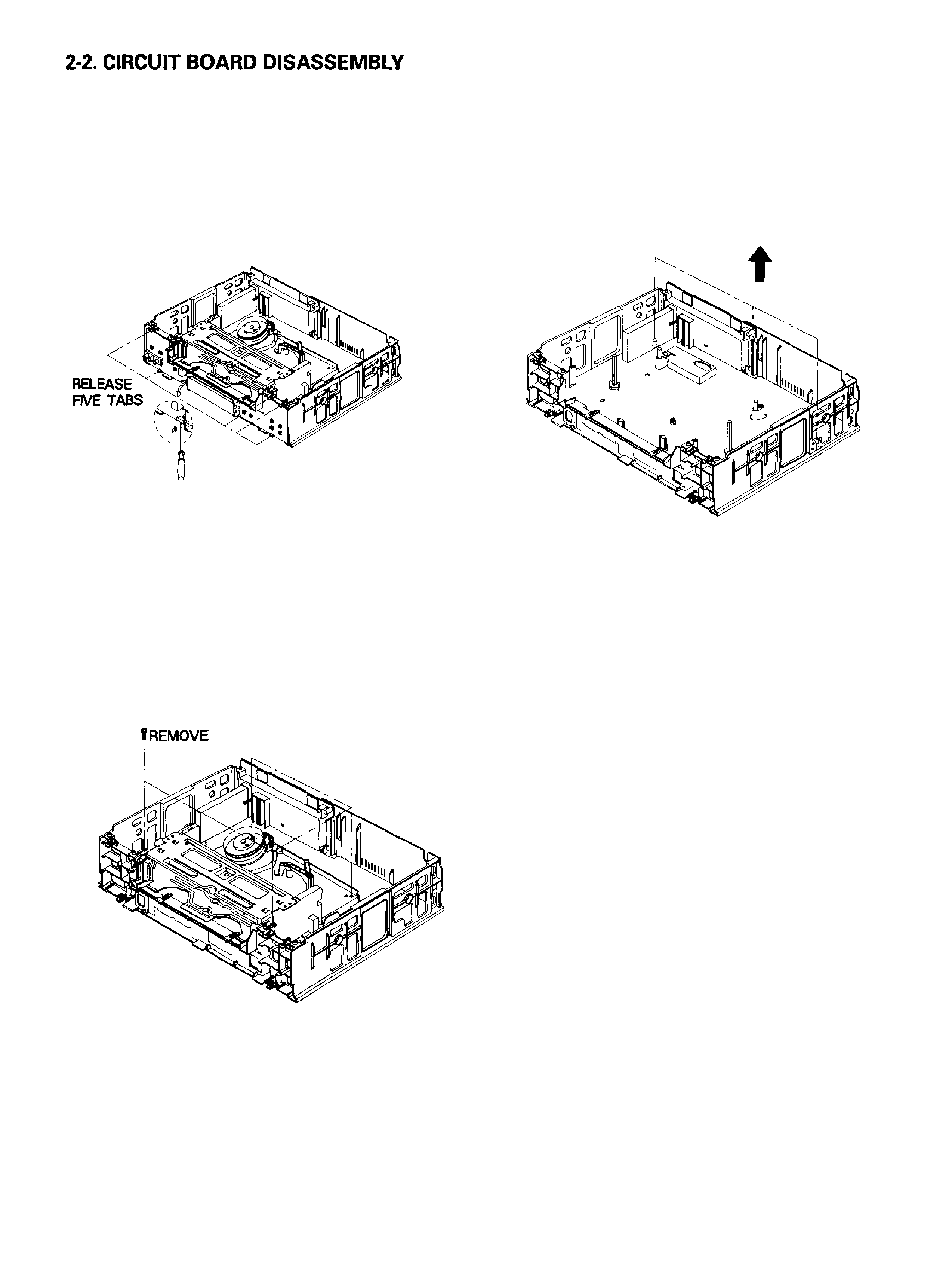
2-2-l. Function PCB Removal
1. Follow the procedures for removing the bottom cover,
the top cabinet and the panel front. (See Fig.1 to 3)
2. Release five (5) tabs on the function board.
3. Release connector(CN701)
gently with using the Driver
as shown Fig. 4
2-2-3. Main circuit board Removal
Fig. 4 Function PCB Removal
2-2-2. Deck Ass'y Removal
1. Follow the procedures for removing the bottom cover,
top cabinet and the front panel ass'y (See Fig.1 to 3)
2. Remove four (4) screws from the bottom and top of the
deck ass'y.
3. Remove two (2) screws from the bottom of the frame.
4. Lift the deck ass'y upward to remove.
FOUR SCREWS
1 .Follow the procedures for removing Fig. 1 to 6
2.Release three (3) tabs from the frame.
3.Pull out the main circuit board in the direction of the
arrow.
RELEASE THREE
TABS
Fig. 6 Main Circuit Board Removal
Fig. 5 Deck ass'y Removal
2-2
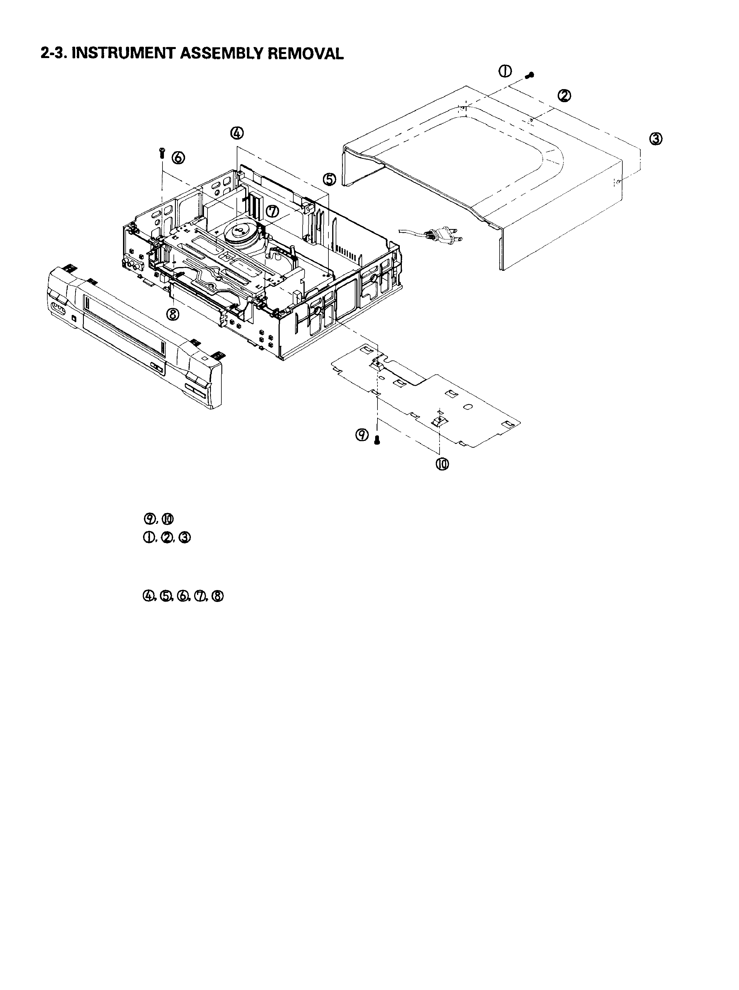
Fig. 7 Instrument Assembly Removal
1. Remove screws
(
1 and release the bottom cover.
2. Remove screws
(
1 and release the top cover.
3. Release the front panel as shown in Fig. 3
4. Release connector (CN701) gently with using the Driver
as shown Fig. 4
5. Remove screws
(
) holding the deck and
follow the procedures on next page.
2-3
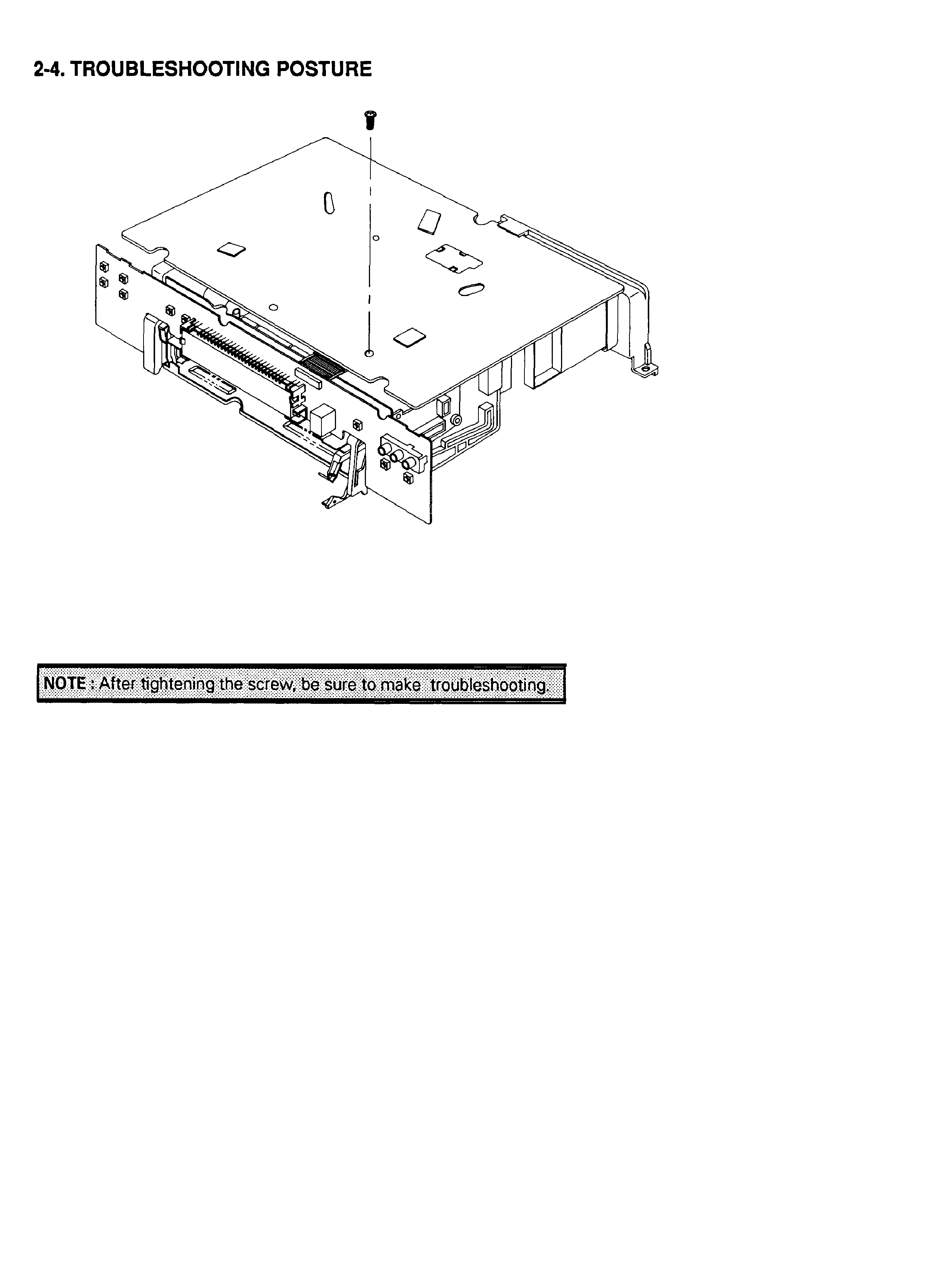
TIGHTEN THE SCREW
Fig. 8 Trouble Shooting Posture
1. Set the main PCB & DECK ass'y as shown in Fig. 8.
2. Tighten the screw.
3. Install the Function PCB to Main PCB
2-4