
SERVICE MANUAL
CORDLESS TELEPHONE
PRINTED IN CHINA, JUNE,1999
FILE NO. 2B0-9805
FT-3808BK

1
CONTENTS
SAFETY PRECAUTIONS-------------------------------------------------------------------------- 1
OPERATING CONTROLS ------------------------------------------------------------------------ 2
ALIGNMENT PROCEDURE --------------------------------------------------------------------- 4
BLOCK DIAGRAM ------------------------------------------------------------------------------- 11
SCHEMATIC DIAGRAMS ---------------------------------------------------------------------- 13
TROUBLESHOOTING HINTS ------------------------------------------------------------------ 15
FREQUENCY CHART ---------------------------------------------------------------------------- 21
IC AND TRANSISTOR VOLTAGE CHART ------------------------------------------------- 22
SEMICONDUCTOR LEAD IDENTIFICATION --------------------------------------------- 28
ELECTRICAL PARTS LOCATION ------------------------------------------------------------ 30
WIRING DIAGRAMS -----------------------------------------------------------------------------3 2
EXPLODED VIEW AND MECHANICAL PARTS LIST ---------------------------------- 34
COMPONENT LIST -------------------------------------------------------------------------------3 8
PACKING PARTS LIST---------------------------------------------------------------------------5 4
SPECIFICATIONS ---------------------------------------------------------------------------------5 5
SAFETY PRECAUTIONS
Before returning any TOSHIBA FT-3808BK to the customer, a safety check of the entire
instrument should be made. The service technician must be sure that no protective device
built into the instrument by the manufacturer has become defective or inadvertently
degraded during servicing.
1. WARNING:
Alterations of the design or circuitry of these models should not be made.
Any design changes or additions such as, but not limited to, circuit modifications, auxiliary
speaker jacks, switches, grounding, active or passive circuitry, etc. may alter the safety
characteristics of these models and potentially create a hazardous situation for the user.
Any design alterations or additions will void the manufacturer's warranty and will further
relieve the manufacturer of responsibility for personal injury or property damage resulting
therefrom.
2. PRODUCT SAFETY NOTICE
Many electrical and mechanical parts in this chassis have special characteristics. These
characteristics often pass unnoticed and the protection afforded by them cannot necessarily
be obtained by using replacement component rated for higher voltage, wattage, etc.
Replacement parts that have these special safety characteristics are identified in this
manual and its supplements; electrical components having such features are identified by a
! in the schematic diagram and the parts list. Before replacing any of these components
read the parts list in this manual carefully. The use of substitute replacement parts that do
not have the same safety characteristics as specified in the parts list may create shock, fire
or other hazards.
2
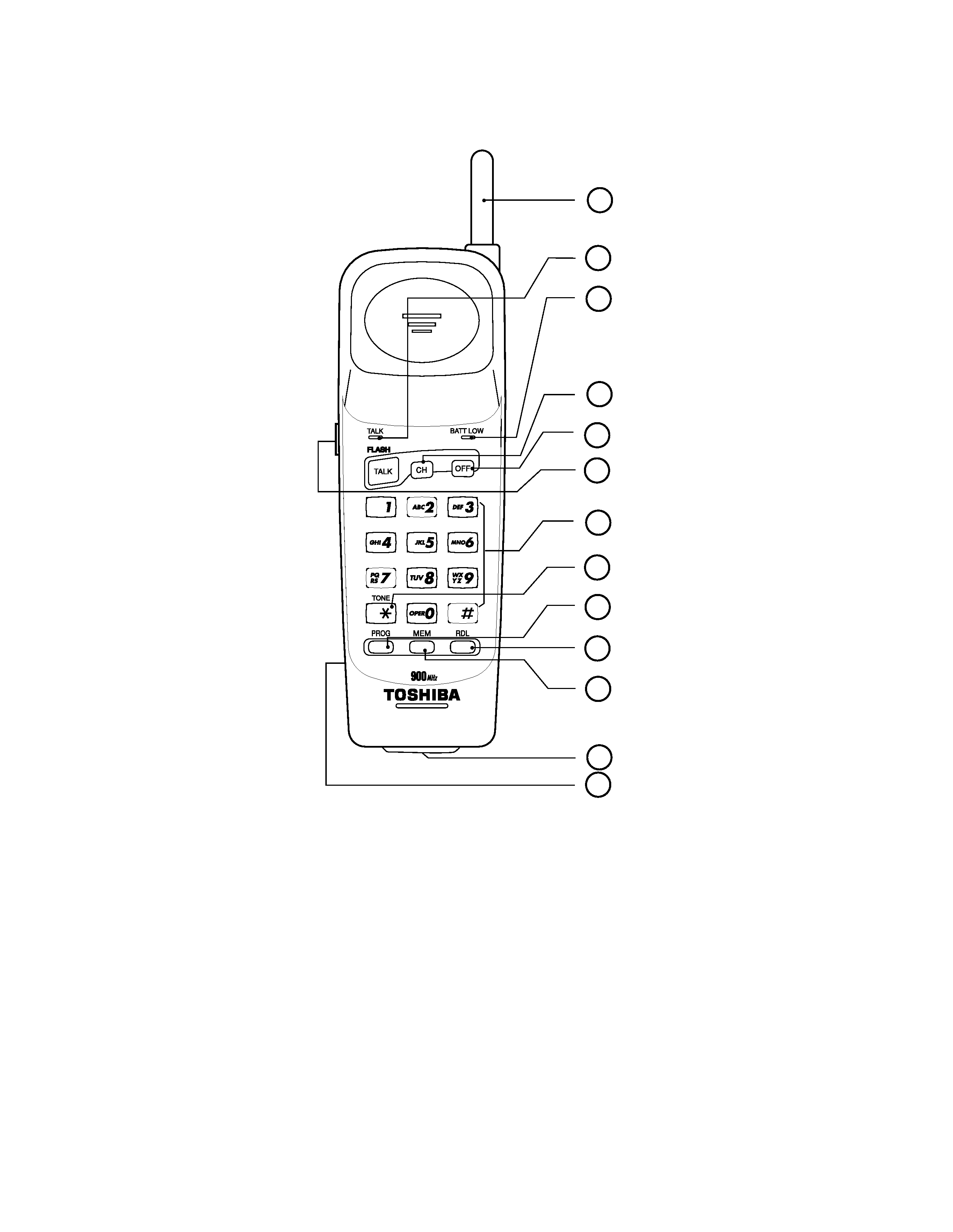
MAIN FEATURES ON HANDSET
1. Helical Antenna - Durable high -gain helical antenna.
2. TALK / FLASH Key & Indicator - Places the handset into talk mode when used away from the base unit/Access
Services such as Call Waiting and Call Forwarding . The indicator lights when the handset is in talk mode.
3. BATT LOW & Indicator - Blinks on and off when the handset battery needs to be charged.
4. CHANNEL CHANGE - Switch to a new channel during conversation.
5. OFF Key - Places the handset into standby mode.
6. Volume H/L Control - Control the loudness of the receiver.
7. Dialing Keys - Used for dialing numbers, storing numbers in memory.
8. TONE - Temporary set the telephone into TONE mode.
9. PROGRAM - Used when storing numbers in the memory.
10. REDIAL - Redial the last number dialed.
11. MEMORY - To dial a number from memory.
12. Charging Contacts - Provides power to charge the handset when it is placed on the base unit.
13. BATTERY PACK (BACK)
2
3
1
4
5
6
7
8
9
10
11
12
OPERATING CONTROLS
13
3
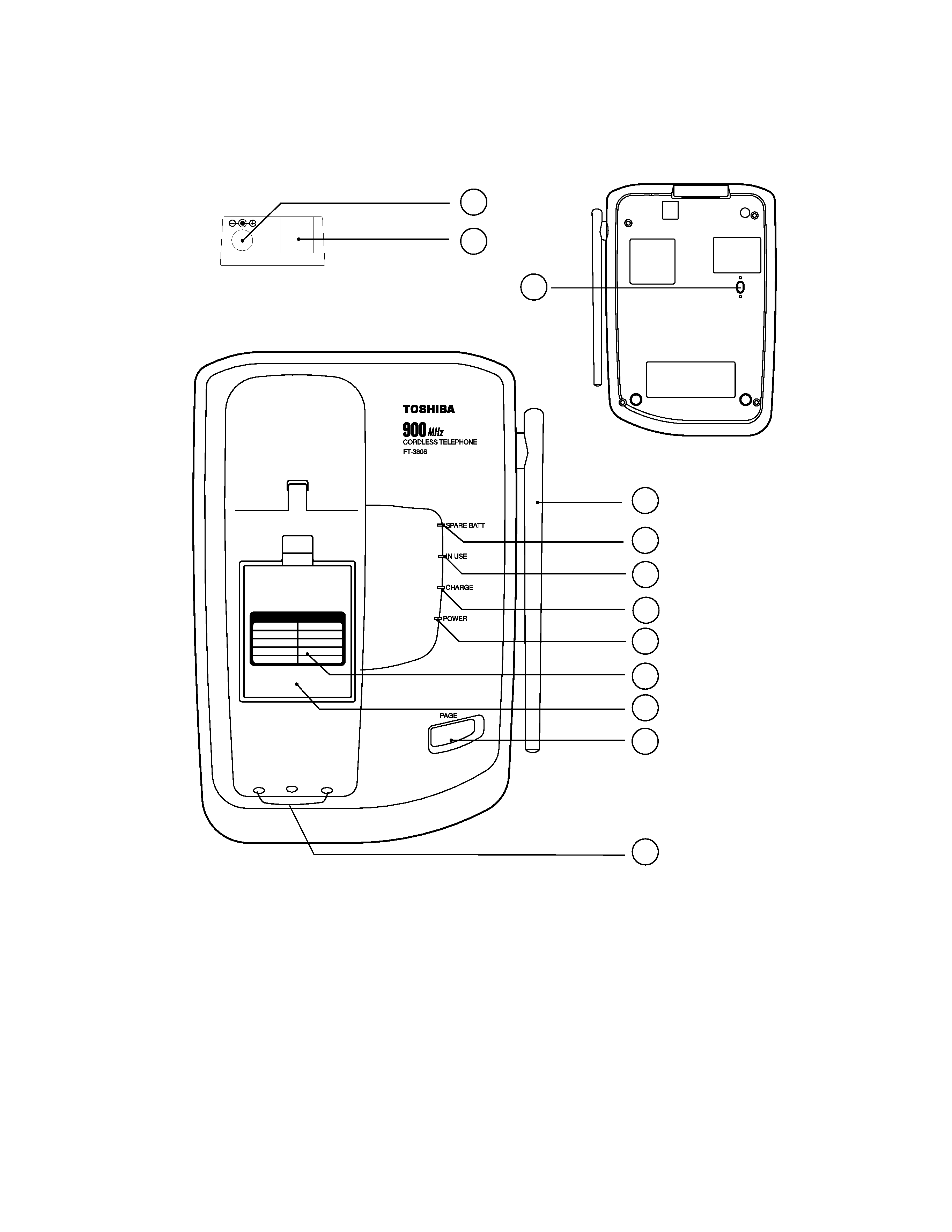
1. Phone Cord Jack -Plugs one end of the telephone line cord into standard RJ11C telephone line jack and the other end into
this jack for connecting the base unit to the telephone line.
2. Antenna - Durable high-fain rod antenna.
3. SPARE BATT Indicator - Illuminates steadily when a battery is placed in the base unit charge cradle.
4. IN-USE Indicator - Illuminates when handset is off hook (line engaged).
5. CHARGE Indicator - Goes on when the handset is in the cradle and the battery is charging.
6. POWER Indicator - Illuminates when power is applied to base unit.
7. Memory Dialing cord - Memeory location recording.
8. PAGE - To page the handset, press page key once. Pressing the PAGE a second time will cancel the page.
9. Charging Contacts - Provides power to charge the handset when it is placed onthe base unit.
10. TONE/PULSE Switch - Set the dialing mode between DTMF and PULSE.
11. POWER ADAPTOR JACK - Insert one of the plugs into the jack.
12. SPARE BATTERY DOOR - Install the spare battery pack.
MAIN FEATURES ON BASE UNIT
BACK SIDE OF BASE UNIT
TEL.LINE
DC 9V
REAR SIDE OF BASE UNIT
11
2
3
4
5
6
7
8
1
1
2
3
4
5
6
7
8
9
0
SPEED DIAL INDEX
12
9
10

4
ALIGNMENT PROCEDURE
Perform the alignment of the Handset & Base using the test mode described below:
1. Test mode for Handset unit:
1.1 Connecting the 3.6VDC power supply to the battery contact.
1.2 Pressing the "#" and "3" keys at the same time, both "IN_USE LED" and
"LOW_ BATT LED" will be on.
1.3 To change channel, press the CHANNEL key.
1.4 To toggle TX power , press the PROG key.
1.5 To toggle RX power, press the MEM key.
1.6 To toggle TX attenuater, press the REDIAL key.
1.7 To change PLL gain mode, lowest (4 steps) ! highest, Press the PHONE key.
1.8 Pressing OFF key to exit from test mode.
1.9 LED indication.
IN USE LED "ON"
LOW BATT LED "ON"
TX power on
RX Power on
2. Test mode for Base unit:
2.1 Apply AC power by connecting the AC adaptor to Base unit, The POWER LED
will illuminate.
2.2 Pressing and hold the PAGE button, then, slide the TONE/PULSE switch from
PULSE to TONE to enter test mode, The IN_USE LED and the CHARGE LED
will illuminate.
2.3 Change Mode:
Press and hold the PAGE button for 1-2 seconds. You will change to the next mode.
once the charge LED change state (1! 0 or 0 ! 1).
MODE
Charge LED
Function
Press PAGE button
1
ON
Change RF channel
0-9 (default 5)
2
OFF
Toggle RF transmitter power
Default on
3
ON
Unused
4
OFF
Generate single tone from
DTMF table for 3 seconds,
There are 8 tones in the table.
697, 770, 852, 941, 1209,
1336, 1477, 1633 Hz default
is 697Hz.