
SERVICE MANUAL
Projection Television
56HM195
62HM195
72HM195
FILE NO. 020-200523GR
Published in Japan Sep. 2005 (YC)
TOSHIBA CORPORATION 2005
The above models are classified as green products (*1), as indicated by the underlined serial numbers. This Service Manual
describes replacement parts for the green products. When repairing these green products, use the parts described in this
manual and lead-free solder (*2).
For (*1) and (*2), see the next page.

- 2 -
TABLE OF CONTENTS
SAFETY INSTRUCTIONS .............................................................................................................................................. 3
SERVICE MODE ............................................................................................................................................................ 4
SETTING & ADJUSTING DATA ...................................................................................................................................... 9
LAMP UNIT REPLACEMENT ....................................................................................................................................... 10
PARTS REPLACEMENT IN LIGHT ENGINE.................................................................................. .............................
13
LIGHT ENGINE REPLACEMANT.................................................................................................................................
14
EXPLODED VIEW ........................................................................................................................................ ................ 17
MECHANICAL DISASSEMBLY .................................................................................................................................... 18
CHASSIS REPLACEMENT PARTS LIST ..................................................................................................................... 19
PC BOARDS TOP AND BOTTOM VIEW ..................................................................................................................... 29
TERMINAL VIEW OF TRANSISTORS ......................................................................................................................... 47
CIRCUIT BLOCK DIAGRAM ........................................................................................................................................ 52
APPENDIX:
CIRCUIT DIAGRAM
(*1)
GREEN PRODUCT PROCUREMENT
The EC is actively promoting the WEEE & RoHS Directives that define standards for recycling
and reuse of Waste Electrical and Electronic Equipment and for the Restriction of the use of
certain Hazardous Substances. From July 1, 2006, the RoHS Directive will prohibit any
marketing of new products containing the restricted substances.
Increasing attention is given to issues related to the global environmental. Toshiba Corporation
recognizes environmental protection as a key management tasks, and is doing its utmost to
enhance and improve the quality and scope of its environmental activities. In line with this,
Toshiba proactively promotes Green Procurement, and seeks to purchase and use products,
parts and materials that have low environmental impacts.
Green procurement of parts is not only confined to manufacture. The same green parts used in
manufacture must also be used as replacement parts.
(*2)
LEAD-FREE SOLDER
This product is manufactured using lead-free solder as a part of a movement within the consumer
products industry at large to be environmentally responsible. Lead-free solder must be used in the
servicing and repair of this product.
WARNING
This product is manufactured using lead free solder.
DO NOT USE LEAD BASED SOLDER TO REPAIR THIS PRODUCT !
The melting temperature of lead-free solder is higher than that of leaded solder by 86
°F to 104°F
(30
°C to 40°C). Use of a soldering iron designed for lead-based solders to repair product made
with lead-free solder may result in damage to the component and or PCB being soldered. Great
care should be made to ensure high-quality soldering when servicing this product
especially
when soldering large components, through-hole pins, and on PCBs
as the level of heat
required to melt lead-free solder is high.
- 3 -
Many electrical and mechanical parts in this chassis have special safety-related characteristics. These characteristics are
often passed unnoticed by a visual inspection and the protection afforded by them cannot necessarily be obtained by using
replacement components rated for higher voltage, wattage, etc. Replacement parts which have these special safety charac-
teristics are identified in this manual and its supplements; electrical components having such features are identified by the
international hazard symbols on the schematic diagram and the parts list.
Before replacing any of these components, read the parts list in this manual carefully. The use of substitute replacement
parts which do not have the same safety character istics as specified in the parts list may create shock, fire, or other hazards.
PRODUCT SAFETY NOTICE
SAFETY INSTRUCTIONS
WARNING: Service should not be attempted by anyone unfamiliar with the necessary precautions on this receiver.The following
are the necessary precautions to be observed before servicing this chassis.
1. An isolation transformer should be connected in the power line between the receiver and the AC line before any service is
performed on the receiver.
2. When replacing a chassis in the cabinet, always be certain that all the prospective devices are put back in place, such as;
non-metallic control knobs, insulating covers, shields, isolation resistor-capacitor network etc.
SAFETY PRECAUTION
- 4 -
3. SELECTING THE ADJUSTING ITEMS
1) Every pressing of CHANNEL
button in the service mode changes the adjustment items in the order of table-2.
(
button for reverse order)
Refer to table-1 for preset data of adjustment mode.
(See SETTING & ADJUSTING DATA on page 9)
4. ADJUSTING THE DATA
1) Pressing of VOLUME
or
button will change the value of data in the range from 00H to FFH. The variable range
depends on the adjusting item.
5. EXIT FROM SERVICE MODE
1) Pressing POWER button to turn off the TV once.
SERVICE MODE
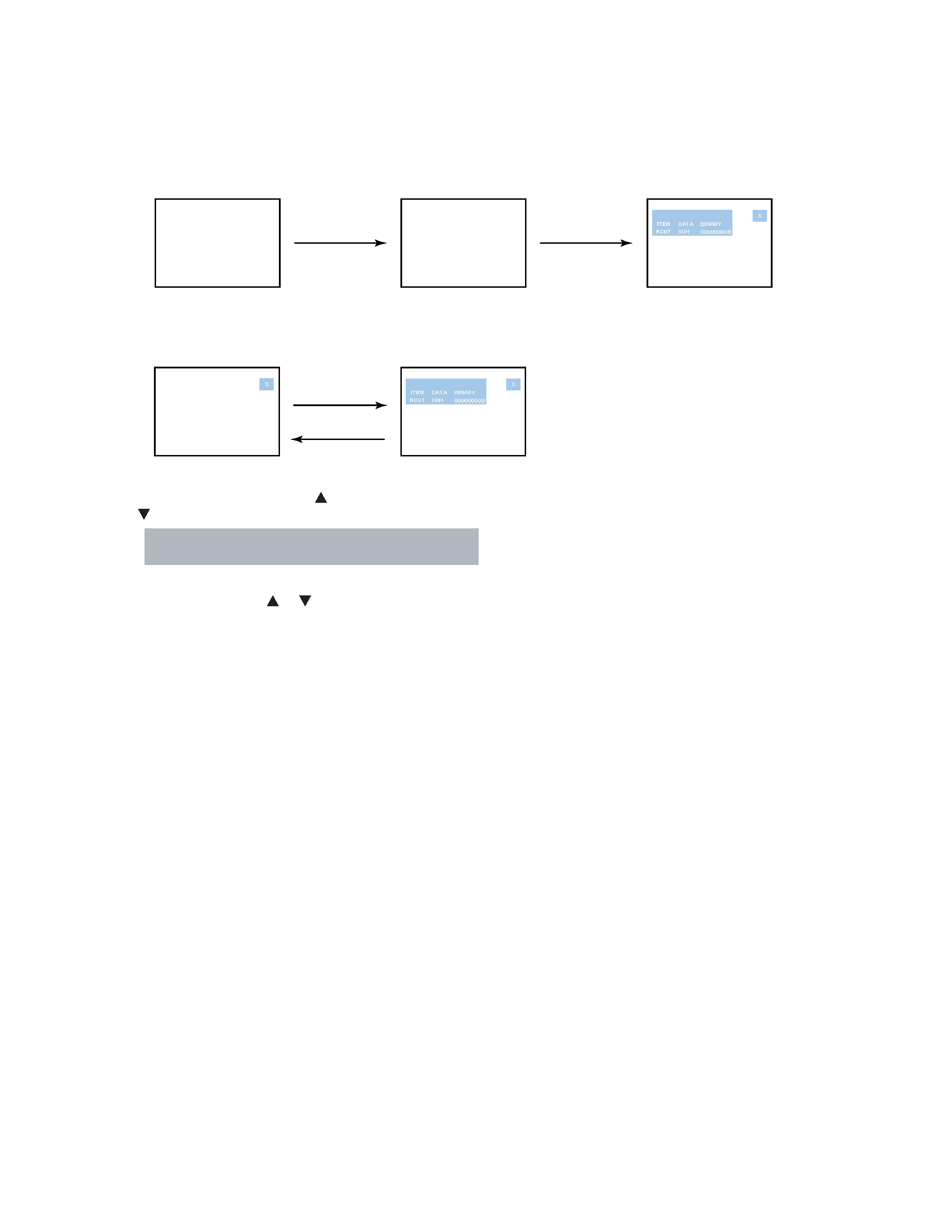
1. ENTERING SERVICE MODE
MUTE
(Service mode display)
3) While pressing the MUTE button,
press MENU button on TV set.
2) Press MUTE button
again and keep pressing.
1) Press MUTE button twice
on Remote Control.
2. DISPLAYING THE ADJUSTMENT MENU
Adjustment mode
Press
Press
Service mode
1) Press MENU button on Remote Control.
- 5 -
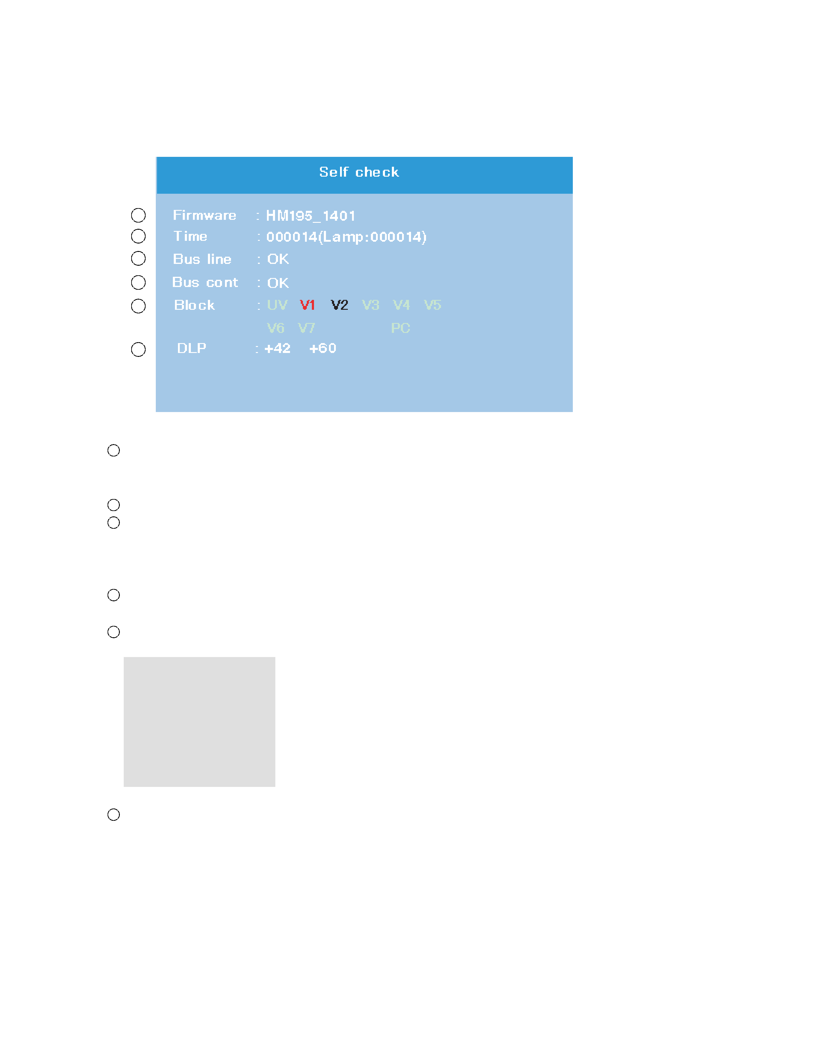
6. SELF DIAGNOSTIC FUNCTION
1)
Press "9" button on Remote Control during display of adjustment menu in the service mode.
The diagnosis will begin to check if interface among IC's is executed properly.
2)
During diagnosis, the following displays are shown.
Firmware :
Version information of microprocessor
In case of file name :
HM195 and Version : 1401 indicates[HM195_1401].
Time :
Total brightness hour of the projection lamp. (Unit : H)
Bus line : --"OK" is normal
"SCL-GND"(Red indication) : SCL-GND short circuit
"SDA-GND"(Red indication) : SDA-GND short circuit
"SCL-SDA"(Red indication) : SCL-SDA short circuit
Bus cont : --- "OK" is normal.
NG is abnormal(Red indication), when type name of semiconductor indicates.
Block
UV : TV reception mode
V1 : VIDEO 1 input mode
V2 : VIDEO 2 input mode
V3 :
VIDEO 3 input mode
V4 :
ColorStream HD-1 IN
V
5 : ColorStream HD-2 IN
V
6 : HDMI IN 1
V
7 : HDMI IN 2
microprocessor into the unit.
DLP : Thermal sensor values information that indicates both of nearby the projection lamp and DMD
1
2
3
4
5
6
1
2
3
4
5
6