
TOSHIBA CORPORATION
1-1, SHIBAURA 1- CHOME, MINATO-KU, TOKYO 105-8001, JAPAN
FILE NO. 020-200227
SERVICE MANUAL
PUBLISHED IN JAPAN,
Dec. 2002
So
COLOR TELEVISION
N2PSL Chassis
57HLX82
(TAC0291)

2
GENERAL
ADJUSTMENTS
SPECIFIC
INFORMATIONS
TABLE OF CONTENTS
CHAPTER 1 GENERAL ADJUSTMENTS
SAFETY INSTRUCTIONS .............................................................................................................................................. 3
SERVICE MODE ............................................................................................................................................................ 4
ELECTRICAL ADJUSTMENT ........................................................................................................................................ 5
CONVERGENCE ADJUSTMENT .................................................................................................................................. 8
CIRCUIT CHECKS ....................................................................................................................................................... 11
CHAPTER 2 SPECIFIC INFORMATIONS
SETTING & ADJUSTING DATA .................................................................................................................................... 12
LOCATION OF CONTROLS ......................................................................................................................................... 13
PROGRAMMING CHANNEL MEMORY ....................................................................................................................... 15
LAMP UNIT REPLACEMENT ....................................................................................................................................... 16
CLEANING THE AIR FILTER ....................................................................................................................................... 20
MECHANICAL DISASSEMBLY .................................................................................................................................... 23
CHASSIS REPLACEMENT PARTS LIST ..................................................................................................................... 27
PC BOARDS BOTTOM VIEW ....................................................................................................................................... 57
TERMINAL VIEW OF TRANSISTORS ......................................................................................................................... 64
SPECIFICATIONS .................................................................................................................................................... END
APPENDIX:
CIRCUIT DIAGRAM
3
GENERAL
ADJUSTMENTS
SPECIFIC
INFORMATIONS
Many electrical and mechanical parts in this chassis have special safety-related characteristics. These characteristics are
often passed unnoticed by a visual inspection and the protection afforded by them cannot necessarily be obtained by using
replacement components rated for higher voltage, wattage, etc. Replacement parts which have these special safety charac-
teristics are identified in this manual and its supplements; electrical components having such features are identified by the
international hazard symbols on the schematic diagram and the parts list.
Before replacing any of these components, read the parts list in this manual carefully. The use of substitute replacement
parts which do not have the same safety characteristics as specified in the parts list may create shock, fire, X-ray radia-
tion or other hazards.
PRODUCT SAFETY NOTICE
CHAPTER 1 GENERAL ADJUSTMENTS
SAFETY INSTRUCTIONS
WARNING: Service should not be attempted by anyone unfamiliar with the necessary precautions on this receiver. The following
are the necessary precautions to be observed before servicing this chassis.
1. An isolation transformer should be connected in the power line between the receiver and the AC line before any service is
performed on the receiver.
2. When the replacing a chassis in the cabinet, always be certain that all the prospective devices are put back in place, such
as; non-metallic control knobs,insulating covers, shields, isolation resistor-capacitor network etc.
SAFETY PRECAUTION
4
GENERAL
ADJUSTMENTS
SPECIFIC
INFORMATIONS
4. SELECTING THE ADJUSTING ITEMS
1) Every pressing of CHANNEL s button in the service mode changes the adjustment items in the order of table-2.
(t button for reverse order)
Refer to table-1 for preset data of adjustment mode.
(See SETTING & ADJUSTING DATA on page 12)
5. ADJUSTING THE DATA
1) Pressing of VOLUME s or t button will change the value of data in the range from 00H to FFH. The variable range
depends on the adjusting item.
6. EXIT FROM SERVICE MODE
1) Pressing POWER button to turn off the TV once.
I INITIALIZATION OF MEMORY DATA OF QA02
After replacing QA02, the following initialization is required.
1. Enter the service mode, then select any register item.
2. Press and hold the RECALL button on the Remote, then press the CHANNEL s button on the TV. The initialization of
QA02 has been complated.
3. Check the picture carefully. If necessary, adjust any adjustment item above.
Perform "Programming Channel Memory" on the owner's manual.
CAUTION: Never attempt to initialize the data unless QA02 has been replaced.
SERVICE MODE
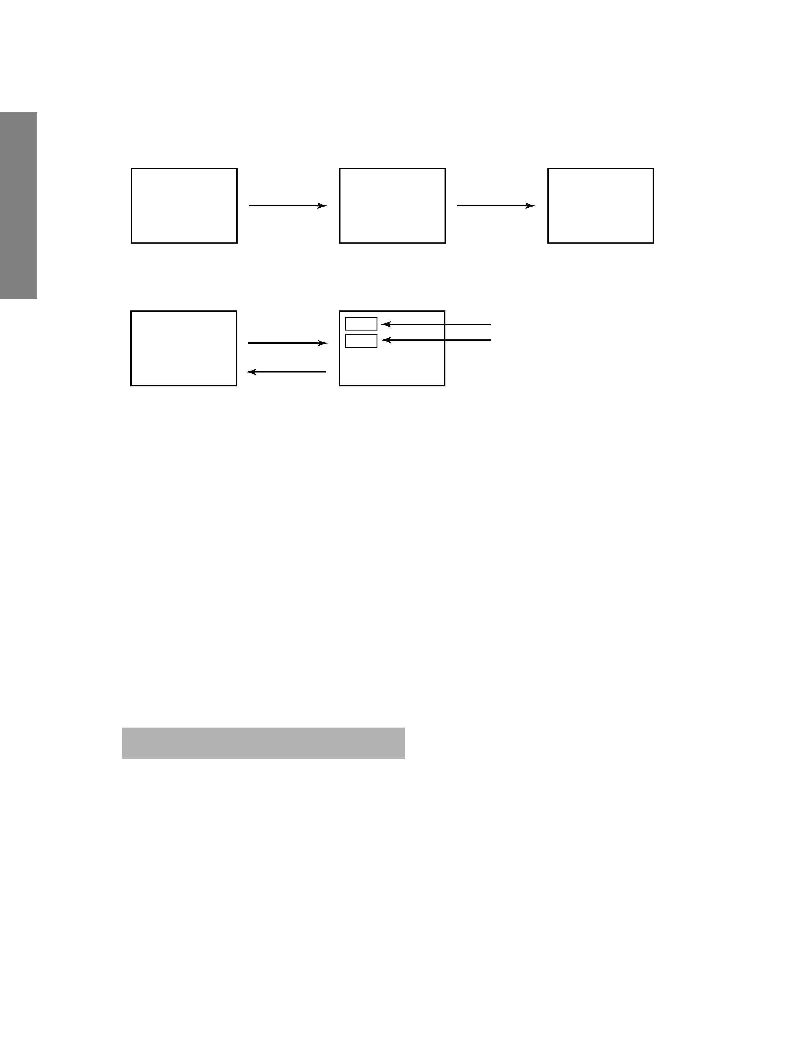
1. ENTERING TO SERVICE MODE
MUTE
S
(Service mode display)
3) While pressing the MUTE button,
press MENU button on TV set.
2) Press MUTE button
again to keep pressing.
1) Press MUTE button twice
on Remote Control.
2. DISPLAYING THE ADJUSTMENT MENU
Adjustment mode
Press
Press
Service mode
Item
Data
S
3. KEY FUNCTION IN THE SERVICE MODE
The following key entry during display of adjustment menu provides special functions.
Screen adjustment mode ON/OFF:
TV (ANT)/VIDEO button (on TV)
Selection of the adjustment items :
Channel s/t (on TV or Remote)
Change of the data value :
Volume s/t (on TV or Remote)
Adjustment menu mode ON/OFF :
MENU button (on TV)
Initialization of the memory (QA02) :
RECALL + Channel button on TV (s)
Initialization of the self diagnostic data:
RECALL + Channel button on TV (t)
Bus OFF:
RECALL + Vol :
"RCUT" selection :
1 button
"GCUT" selection :
2 button
"BCUT" selection :
3 button
"SCNT" selection :
4 button
"SCOL" selection :
5 button
"TNTC" selection :
6 button
Convergence adj :
7 button
Self diagnostic display :
9 button
1) Press MENU button on TV.
5
GENERAL
ADJUSTMENTS
SPECIFIC
INFORMATIONS
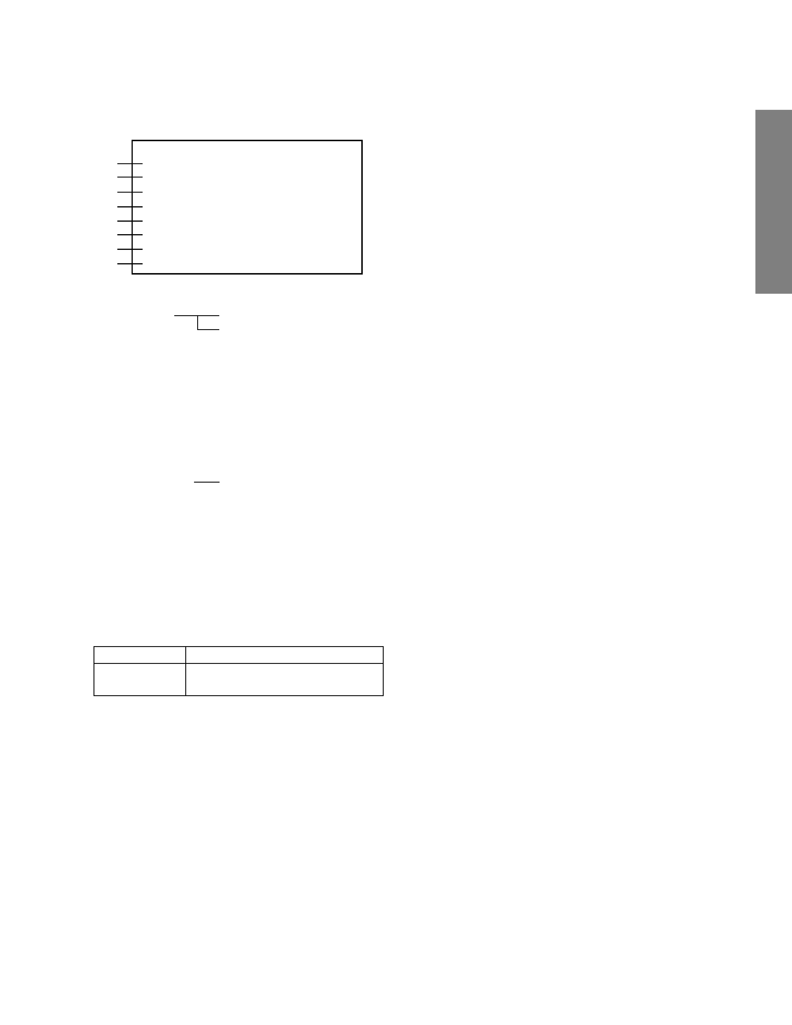
7. SELF DIAGNOSTIC FUNCTION
1) Press "9" button on Remote Control during display of adjustment menu in the service mode.
The diagnosis will begin to check if interface among IC's are executed properly.
2) During diagnosis, the following displays are shown.
Part number of microprocessor (QA01)
Operation number of protection circuit (current limiter) . . . . "000" is normal.
BUS line check
"OK" ................... Normal
"SCL-GND" or "NG" ........... SCL-GND short circuit
"SDA-GND" or "NG" ........... SDA-GND short circuit
"SCL-SDA" or "NG" ............ SCL-SDA short circuit
BUS line ACK (acknowledge) check
"OK" ................... Normal
Display of Location Number . . . . NG
(Display example)
"QA02 NG", "H001 NG", "Q501 NG" etc.
Note: The indication of failure place is only one place though failure places are plural. When
repair of a failure place finishes, the next failure place is indicated. (The order of priority of
indication is left side.)
Sync. signal check
Green display ..... Normal
Red display ........ NG
MAIN ........ Main sync
SUB .......... Sub sync (when turn on the PIP)
ID code for TV Set
Version of "EEP"
Data for "OPT"
SELF CHECK
NO. 23 * * * * * *
POWER
: 000
BUS LINE : OK
BUS CONT : OK
BLOCK : MAIN SUB
SET ID : 01
EEP VER : 02
OPT1 : 05
OPT2 : 70
8. Selection of test signal
1) The SGA terminal (Pin 21) should be 1-kHz rectangular wave when the test voice signal is OFF.
2) The selection of video test signals is shifted cyclicly by a VIDEO key (remote control)
Test signal No.
Name of Pattern
0
Signal OFF
5
Total white signal
The video test signals are output by a convergence IC for PJ and by OSD for direct monitoring.
3) Test signal No. and video mode are last memorized for factory shipping mode.
Note: The test signal is not output when an input is made for a pin (pins) of the VIDEO 1 terminal.
9. Power control and current limiter detection (self diagnosis)
9-1 Power control
1) During STANBY: Set the POWER terminal (Pin15) to "L".
LED terminal (Pin 16)
2) During SET ON: Set the POWER terminal to Hi-z (input mode).
Set the LED terminal to "H".
9-2 Current limiter detection
1) When "L" is detected for 2 seconds or more after monitoring the POWER terminal during SET ON, it is jugded that the
current limiter is operated.
2) Turn ON/OFF the LED terminal every 0.5 second.
3) Make increment for the number of the current limiter detection times during "SELF CHECK".