
SERVICE MANUAL
Projection Television
52HMX94
62HMX94
Published in Japan, Jan. 2005 (YC)
FILE NO. 020-200423
REVISION 2
DOCUMENT CREATED IN JAPAN, Jan., 2005

- 2 -
TABLE OF CONTENTS
CHAPTER 1 GENERAL ADJUSTMENTS
SAFETY INSTRUCTIONS .............................................................................................................................................. 3
SERVICE MODE ............................................................................................................................................................ 4
CHAPTER 2 SPECIFIC INFORMATIONS
SETTING & ADJUSTING DATA ...................................................................................................................................... 7
LAMP UNIT REPLACEMENT ......................................................................................................................................... 8
PARTS REPLACEMENT IN LIGHT ENGINE.................................................................................. .............................
11
LIGHT ENGINE REPLACEMANT.................................................................................................................................
13
EXPLODED VIEW ........................................................................................................................................ ................ 15
MECHANICAL DISASSEMBLY .................................................................................................................................... 16
CHASSIS REPLACEMENT PARTS LIST ..................................................................................................................... 17
PC BOARDS TOP AND BOTTOM VIEW ..................................................................................................................... 26
CIRCUIT BLOCK DIAGRAM ........................................................................................................................................ 47
APPENDIX:
CIRCUIT DIAGRAM
- 3 -
Many electrical and mechanical parts in this chassis have special safety-related characteristics. These characteristics are
often passed unnoticed by a visual inspection and the protection afforded by them cannot necessarily be obtained by using
replacement components rated for higher voltage, wattage, etc. Replacement parts which have these special safety charac-
teristics are identified in this manual and its supplements; electrical components having such features are identified by the
international hazard symbols on the schematic diagram and the parts list.
Before replacing any of these components, read the parts list in this manual carefully. The use of substitute replacement
parts which do not have the same safety character istics as specified in the parts list may create shock, fire, or other hazards.
PRODUCT SAFETY NOTICE
CHAPTER 1 GENERAL ADJUSTMENTS
SAFETY INSTRUCTIONS
WARNING: Service should not be attempted by anyone unfamiliar with the necessary precautions on this receiver.The following
are the necessary precautions to be observed before servicing this chassis.
1. An isolation transformer should be connected in the power line between the receiver and the AC line before any service is
performed on the receiver.
2. When replacing a chassis in the cabinet, always be certain that all the prospective devices are put back in place, such as;
non-metallic control knobs, insulating covers, shields, isolation resistor-capacitor network etc.
SAFETY PRECAUTION
- 4 -
3. SELECTING THE ADJUSTING ITEMS
1) Every pressing of CHANNEL
button in the service mode changes the adjustment items in the order of table-2.
(
button for reverse order)
Refer to table-1 for preset data of adjustment mode.
(See SETTING & ADJUSTING DATA on page 8)
4. ADJUSTING THE DATA
1) Pressing of VOLUME
or
button will change the value of data in the range from 00H to FFH. The variable range
depends on the adjusting item.
5. EXIT FROM SERVICE MODE
1) Pressing POWER button to turn off the TV once.
SERVICE MODE
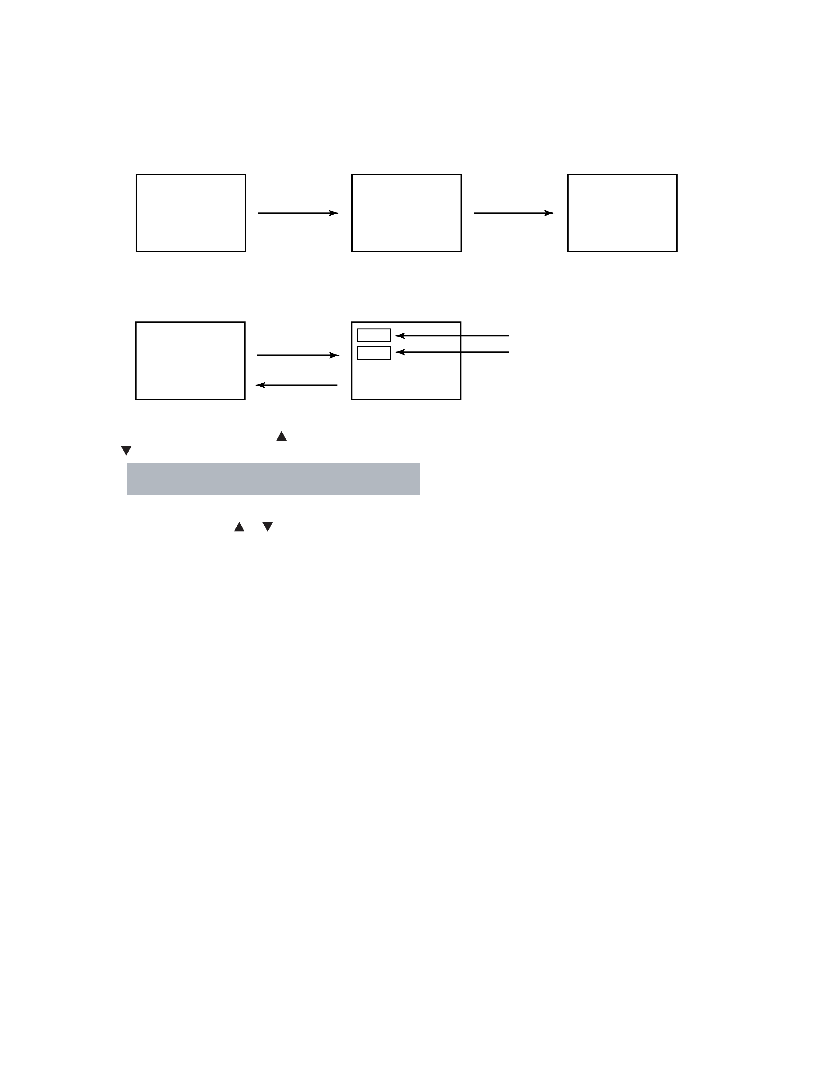
1. ENTERING SERVICE MODE
MUTE
S
(Service mode display)
3) While pressing the MUTE button,
press MENU button on TV set.
2) Press MUTE button
again and keep pressing.
1) Press MUTE button twice
on Remote Control.
2. DISPLAYING THE ADJUSTMENT MENU
Adjustment mode
Press
Press
Service mode
Item
Data
S
1) Press MENU button on TV.
- 5 -
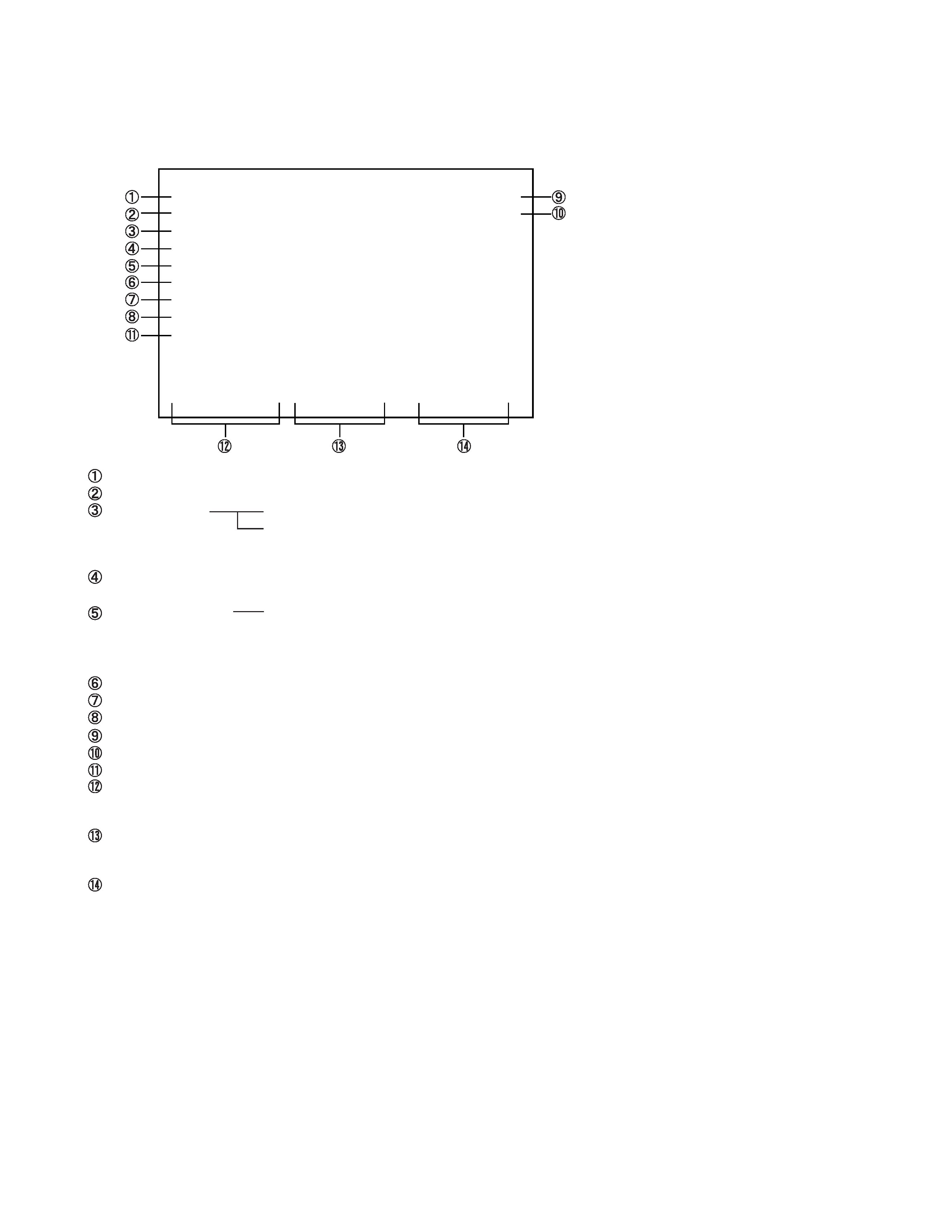
6. SELF DIAGNOSTIC FUNCTION
1) Press "9" button on Remote Control during display of adjustment menu in the service mode.
The diagnosis will begin to check if interface among IC's is executed properly.
2) During diagnosis, the following displays are shown.
Part number of microprocessor (IC609)
Operation number of protection circuit (The number of times of the power supply OFF by fan stop) . . . . "000" is normal.
BUS line check
"OK" ................... Normal
"SCL-GND" or "NG" ........... SCL-GND short circuit
"SDA-GND" or "NG" ........... SDA-GND short circuit
"SCL-SDA" or "NG" ............ SCL-SDA short circuit
BUS line ACK (acknowledge) check
"OK" ................... Normal
Sync. signal check
Green display ..... Normal
Red display ........ NG
MAIN ........ Main sync
SUB .......... Sub sync (when turn on the PIP)
ID code for TV Set
Version of "EEP"
Data for "OPT"
SELF CHECK
NO. 23 * * * * * *
POWER
: 000
BUS LINE : OK
BUS CONT : OK
BLOCK : MAIN SUB
SET ID : 80
E2P VER : 08
OPT1 : 00
OPT2 : A0
SW VER : DLE May 13 2004 17:**:**
HDMI
NO
********
ERR CDDE : 00
BEP
SW VER : 42
E2R VER : 02
TIME
TV
: ******
LAMP :
****
Thermo1 : +51
Thermo2 : +50
Temperature of DMD
Temperature of the color wheel neighborhood
Software version history
HDMI Software
NO *****
.....Serial No.
ERR CODE .....Error Code
BEP Software Version
SW VER : **..... Version
E2P VER : **
EEP ROM Version
Use time
TV
.....TV set on time (hour)
LAMP .....LAMP set on time (hour)
(It may shift from TV set on time.)