TOSHIBA CORPORATION
1-1, SHIBAURA 1- CHOME, MINATO-KU, TOKYO 105-8001, JAPAN
FILE NO. 030-200209
SERVICE MANUAL
COLOUR TELEVISION
C01P Chassis
50PH18Q
PUBLISHED IN JAPAN
Apr. 2002 So

2
GENERAL
ADJUSTMENTS
TABLE OF CONTENTS
CHAPTER 1 GENERAL ADJUSTMENTS
SAFETY INSTRUCTIONS ........................................................................................................................................ 3
CRT ASSEMBLY REPLACEMENT AND MOUNTING .............................................................................................. 4
PICTURE TUBE COMPONENTS ADJUSTMENT .................................................................................................... 6
SERVICE POSITION ................................................................................................................................................ 9
SERVICE MODE .................................................................................................................................................... 10
DESIGN MODE ...................................................................................................................................................... 13
ELECTRICAL ADJUSTMENT ................................................................................................................................. 14
CONVERGENCE ADJUSTMENT .......................................................................................................................... 15
SCREEN AND MIRROR ALIGNMENTS ................................................................................................................ 20
CIRCUIT CHECKS ................................................................................................................................................. 21
CHAPTER 2 SPECIFIC INFORMATIONS
SETTING & ADJUSTING DATA .............................................................................................................................. 22
LOCATION OF CONTROLS ................................................................................................................................... 23
MECHANICAL DISASSEMBLY .............................................................................................................................. 25
CHASSIS AND CABINET REPLACEMENT PARTS LIST ......................................................................................29
PC BOARDS LAYOUT TOP VIEW .......................................................................................................................... 55
PC BOARDS BOTTOM VIEW ................................................................................................................................. 57
TERMINAL VIEW OF TRANSISTORS ................................................................................................................... 70
CIRCUIT BLOCK DIAGRAM .................................................................................................................................. 72
SPECIFICATIONS .............................................................................................................................................. END
APPENDIX:
CIRCUIT DIAGRAM
3
GENERAL
ADJUSTMENTS
CHAPTER 1 GENERAL ADJUSTMENTS
SAFETY INSTRUCTIONS
WARNING: BEFORE SERVICING THIS CHASSIS, READ THE "X-RAY RADIATION PRECAUTION", "SAFETY
PRECAUTION" AND "PRODUCT SAFETY NOTICE" INSTRUCTIONS BELOW.
X-RAY RADIATION PRECAUTION
1. Excessive high voltage can produce potentially hazard-
ous X-RAY RADIATION. To avoid such hazards, the high
voltage must not be above the specified limit. The nominal
value of the high voltage of this receiver is (A) kV at zero
beam current (minimum brightness) under a (C) V AC power
source. The high voltage must not, under any circum-
stances, exceed (B) kV.
Refer to table-1 for high voltage (A), (B) & AC voltage (C).
(See SETTING & ADJUSTING DATA on page 22)
Each time a receiver requires servicing, the high
voltage should be checked following the HIGH
VOLTAGE CHECK procedure in this manual. It is
recommended that the reading of the high voltage
be recorded as a part of the service record. It is
important to use an accurate and reliable high voltage
meter.
2 . The only source of X-RAY RADIATION in this TV
receiver is the picture tube. For continued X-RAY RA-
DIATION protection, the replacement tube must be
exactly the same type tube as specified in the parts
list.
3. Some part in this receiver have special safety-related
characteristics for X-RAY RADIATION protection. For
continued safety, parts replacement should be under-
taken only after referring to the PRODUCT SAFETY
NOTICE below.
SAFETY PRECAUTION
WARNING : Service should not be attempted by anyone unfamiliar with the necessary precautions on this receiver. The
following are the necessary precautions to be observed before servicing this chassis.
1. An isolation transformer should be connected in the power line between the receiver and the AC line before any service
is performed on the receiver.
2. Always discharge the picture tube anode to the CRT conductive coating before handling the picture tube. The picture
tube is highly evacuated and if broken, glass fragments will be violently expelled. Use shatter proof goggles and keep
picture tube away from the unprotected body while handling.
3. When replacing a chassis in the cabinet, always be certain that all the protective devices are put back in place, such as;
non-metallic control knobs, insulating covers, shields, isolation resistor-capacitor network etc.
PRODUCT SAFETY NOTICE
Many electrical and mechanical parts in this chassis have special safety-related characteristics. These characteristics
are often passed unnoticed by a visual inspection and the protection afforded by them cannot necessarily be obtained
by using replacement components rated for higher voltage, wattage, etc. Replacement parts which have these special
safety characteristics are identified in this manual and its supplements; electrical components having such features are
identified by the international hazard symbols on the schematic diagram and the parts list.
Before replacing any of these components, read the parts list in this manual carefully. The use of substitute
replacement parts which do not have the same safety characteristics as specified in the parts list may create shock,
fire, X-ray radiation or other hazards.
4
GENERAL
ADJUSTMENTS
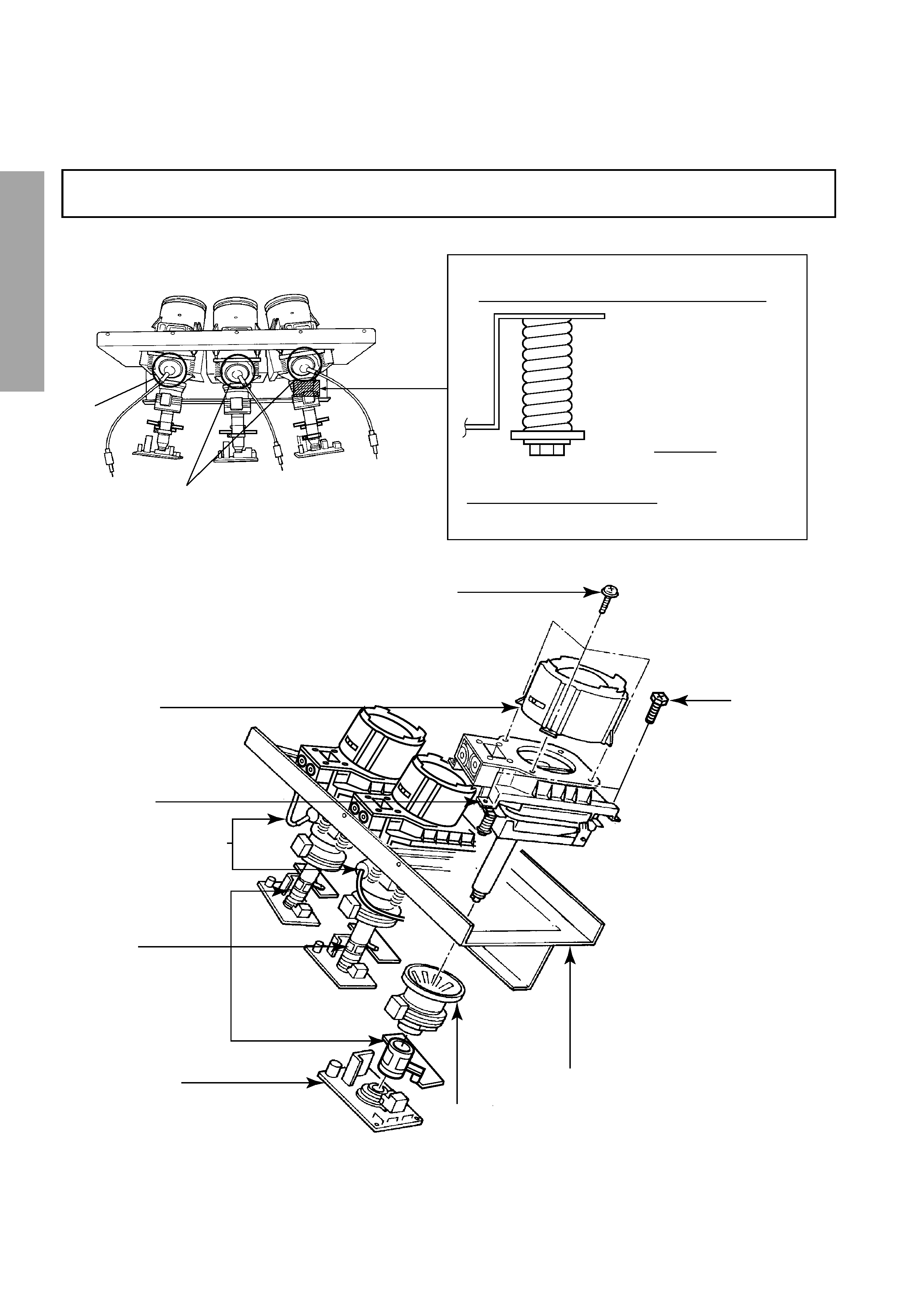
CRT ASSEMBLY REPLACEMENT AND MOUNTING
CAUTION :
DO NOT LOOSEN THE HEX HEAD BOLTS WITH SPRINGS (12 PCS), BECAUSE THOSE ARE FOR
SEALING OF CRT COOLANT.
Lens and Neck Components View
4 Screws
CRT Anode Cap Assembly
S.V.M. Coil
CRT DRIVE Board
Lens Assembly
CRT Assembly
Deflection Yoke and Conver Yoke
CRT Mounting
4 Screws
Attention Serviceman
The Hex Head
Bolts with
Springs. (see
sketch) used on
CRT assembly,
are "NOT"
Adjustment Screws
DO NOT LOOSEN-FLUID
LEAKAGE WILL OCCUR.
5
GENERAL
ADJUSTMENTS
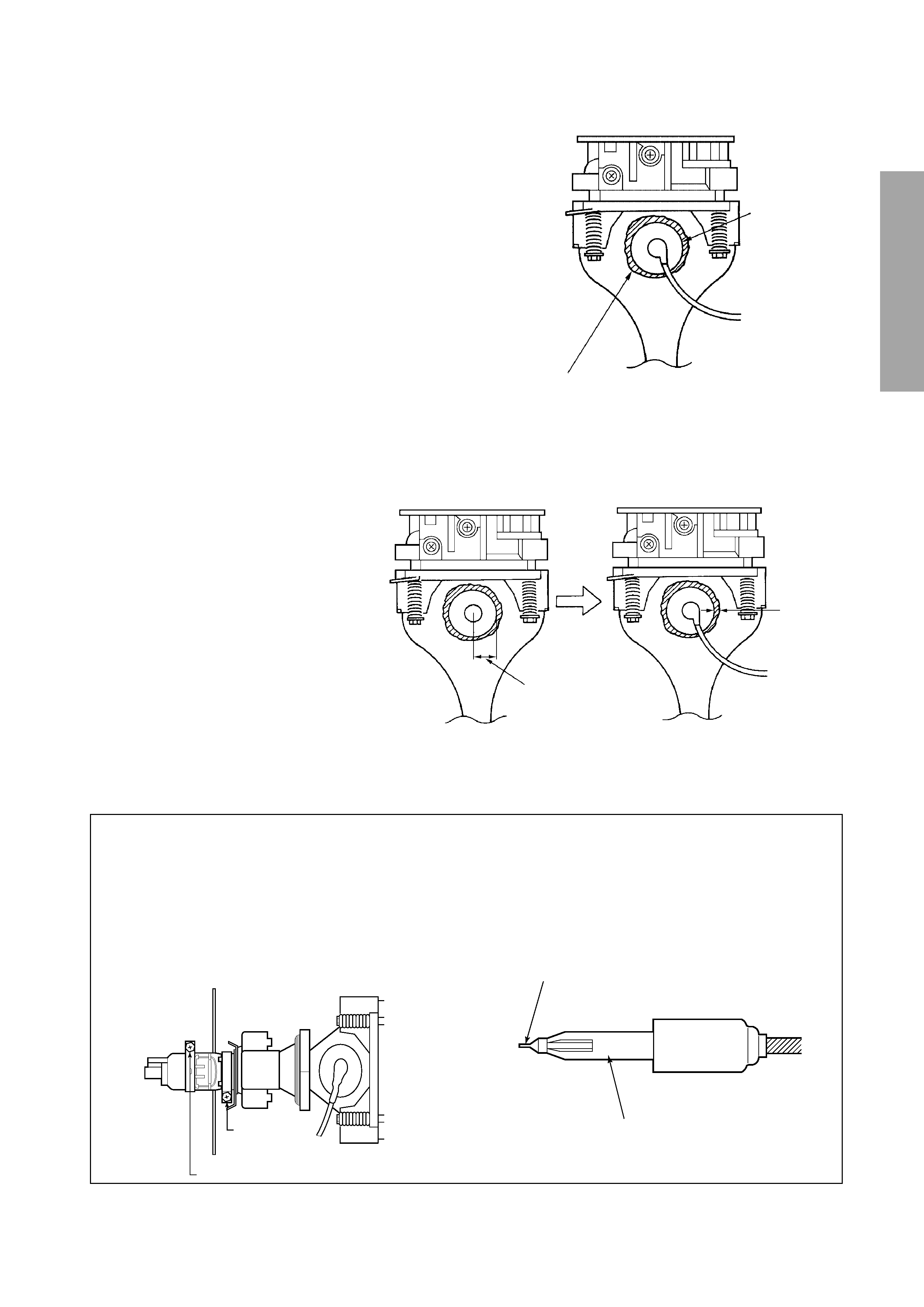
SERVICING PRECAUTIONS
s Check the point of anode lead in a straight
line, if it is winding, please revise it.
Anode lead holder
s Do not use a magnetized screw driver for screws
of Deflection Yoke and Velocity Modulation Coil to
avoid magnetization of electron gun.
Magnetization of electron gun will degrade basic
function and result in unbalance of right and left
shift of user static convergence, and result in no
variable quantity.
s When replacing the anode cap assembly (CRT) or
anode lead assembly (F.B.T.), remove the anode
lead holder from old one and attach the holder
again to new anode lead.
Screw
for D.Y
Screw for SVM coil
Silicon
(On shaded area)
TSE3843W #23960136
2 ~ 5 mm
15 ~ 25 mm
Anode Cap
TO REMOVE CRT (Same procedure for R, G, B)
1. Remove CRT DRIVE Board, S. V. M.
COIL and DEF. YOKE from CRT.
2. Remove Lens Assembly.
3. Detach CRT Anode Cap from CRT.
4. Remove CRT Assembly from CRT
Mounting.
CRT REPLACEMENT (Same procedure for R,
G, B)
Reverse the removal procedures except the
followings.
1. Anode Cable should be replaced with new
one.
See "SERVICING PRECAUTIONS" shown
below.
2. Install silicon (T461B) to the CRT, replace the
Anode cable and put enough silicon again on
around the Anode Cap as illustrated.
CAUTION: Align the Anode cable as illustrated
on page 4.
ADJUSTING PROCEDURE IN REPLACING CRT
1. R.G.B. CUTOFF (SCREEN VR) ADJUSTMENT
(page 6.)
2. R.G.B. FOCUS ADJUSTMENT (page 6.)
3. PICTURE TILT ADJUSTMENT (page 7.)
4. USER CONVERGENCE CENTER CHECK
(Refer to owner's manual.)
5. CENTERING ADJUSTMENT (page 7.)
6. CONVERGENCE ADJUSTMENT (page 15.)
7. WHITE BALANCE ADJUSTMENT (page 14.)
Adjustments are complete.