
TOSHIBA CORPORATION
1-1, SHIBAURA 1- CHOME, MINATO-KU, TOKYO 105-8001, JAPAN
Mar., 2002
FILE NO. 010-200205
SERVICE MANUAL
COLOUR TELEVISION
F1LP Chassis
44A9UH, 44A9UR

2
GENERAL
ADJUSTMENTS
SPECIFIC
INFORMATIONS
TABLE OF CONTENTS
CHAPTER 1 GENERAL ADJUSTMENTS
SAFETY INSTRUCTIONS ........................................................................................................................................ 3
SERVICE MODE ...................................................................................................................................................... 4
DESIGN MODE ........................................................................................................................................................ 7
ELECTRICAL ADJUSTMENTS ................................................................................................................................ 8
SCREEN AND MIRROR ALIGNMENTS ................................................................................................................ 10
CHAPTER 2 SPECIFIC INFORMATIONS
SETTING & ADJUSTING DATA .............................................................................................................................. 11
LOCATION OF CONTROLS ................................................................................................................................... 12
PROGRAMMING CHANNEL MEMORY ................................................................................................................. 14
MECHANICAL DISASSEMBLY .............................................................................................................................. 17
CHASSIS AND CABINET REPLACEMENT PARTS LIST ......................................................................................21
PC BOARDS BOTTOM VIEW ................................................................................................................................. 43
TERMINAL VIEW OF TRANSISTORS ................................................................................................................... 51
CIRCUIT BLOCK DIAGRAM .................................................................................................................................. 53
SPECIFICATIONS .............................................................................................................................................. END
APPENDIX:
CIRCUIT DIAGRAM
3
GENERAL
ADJUSTMENTS
SPECIFIC
INFORMATIONS
CHAPTER 1 GENERAL ADJUSTMENTS
SAFETY INSTRUCTIONS
SAFETY PRECAUTION
WARNING : Service should not be attempted by anyone unfamiliar with the necessary precautions on this receiver. The
following are the necessary precautions to be observed before servicing this chassis.
1. An isolation transformer should be connected in the power line between the receiver and the AC line before any service
is performed on the receiver.
2. When replacing a chassis in the cabinet, always be certain that all the protective devices are put back in place, such as;
non-metallic control knobs, insulating covers, shields, isolation resistor-capacitor network etc.
PRODUCT SAFETY NOTICE
Many electrical and mechanical parts in this chassis have special safety-related characteristics. These characteristics
are often passed unnoticed by a visual inspection and the protection afforded by them cannot necessarily be obtained by
using replacement components rated for higher voltage, wattage, etc. Replacement parts which have these special
safety characteristics are identified in this manual and its supplements; electrical components having such features are
identified by the international hazard symbols on the schematic diagram and the parts list.
Before replacing any of these components, read the parts list in this manual carefully. The use of substitute replacement
parts which do not have the same safety characteristics as specified in the parts list may create shock, fire or other
hazards.
LAMP REPLACEMENT CAUTION
When replacing the lamp of LCD projection TV, use Lamp Module Kit.
Be sure to read the caution in the instruction manual before replacing.
4
GENERAL
ADJUSTMENTS
SPECIFIC
INFORMATIONS
SERVICE MODE
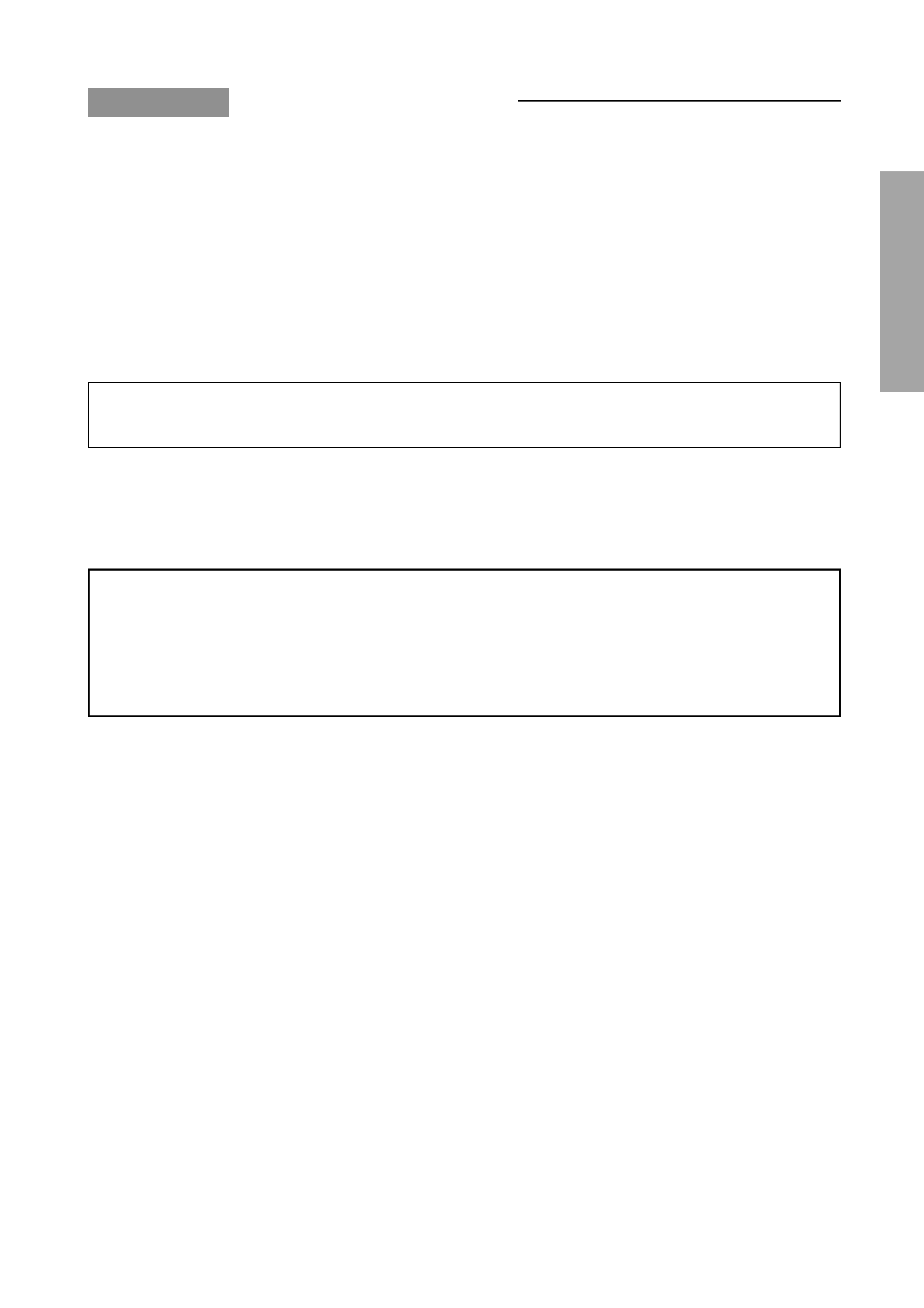
1. ENTERING TO SERVICE MODE
S
(Service mode display)
Item
Data
3) While pressing the o button,
press MENU button on TV set.
2) Press o button again to
keep pressing.
2. DISPLAYING THE ADJUSTMENT MENU
1) Press MENU button on TV.
3. KEY FUNCTION IN THE SERVICE MODE
The following key entry during display of adjustment menu provides special functions.
Frequency of lamp replacement
CALL + RGB button
Test signal selection :
a button (on Remote)
Selection of the adjustment items :
Channel s/t (on TV or Remote)
Change of the data value :
Volume ; +/ (on TV or Remote)
Adjustment menu mode ON/OFF :
MENU button (on TV)
Initialization of the memory (QA02) :
CALL + Channel button on TV (s)
Reset the count of operating protect
circuit to "00":
CALL + Channel button on TV (t)
"CSBRT" selection :
1 button
"SRY" selection :
2 button
"SBY" selection :
3 button
"CNTX" (or "SCNT") selection :
4 button
"COLP" (or "OTHER") selection :
5 button
"TNTC" or "TNTV"selection :
6 button
Test audio signal ON/OFF (1kHz) :
8 button
Self diagnostic display ON/OFF :
9 button
1) Press o button once on
Remote Control.
Adjustment mode
Press
Press
Service mode
Item
Data
S
Color thickness correction
note: Displayed differently as shown below, de-
pending on the setting of the receiving color
system.
COLP (PAL)
COLC (NTSC)
COLS (SECAM)
CAUTION : Never try to perform initialization unless you have changed the memory IC.
5
GENERAL
ADJUSTMENTS
SPECIFIC
INFORMATIONS
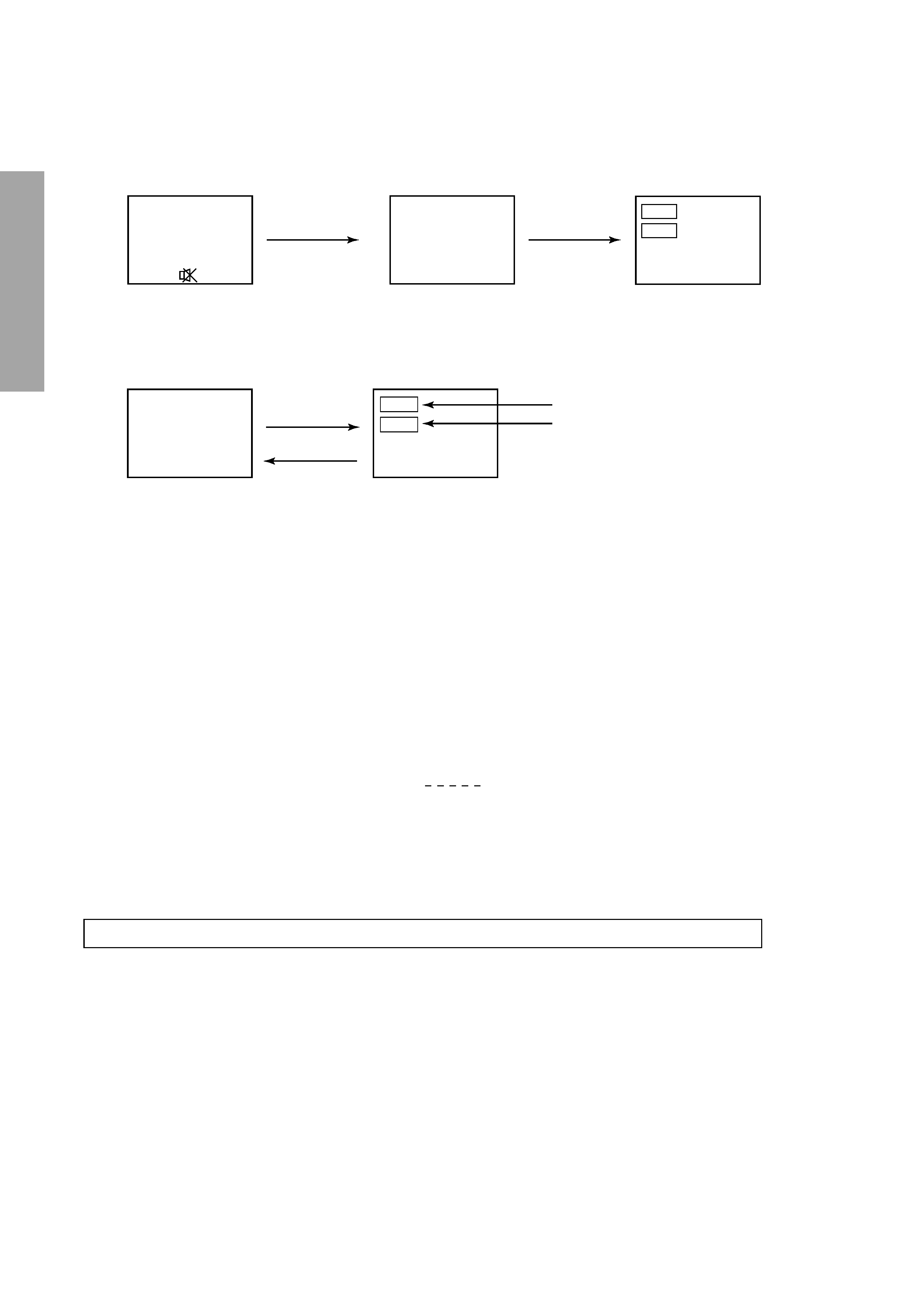
4. SELECTING THE ADJUSTING ITEMS
1) Every pressing of CHANNEL s button in the service mode changes the adjustment items in the order of table-2.
(t button for reverse order)
Refer to table-2 for preset data of adjustment mode.
(See SETTING & ADJUSTING DATA on page 11)
5. ADJUSTING THE DATA
1) Pressing of VOLUME ; +/ button will change the value of data in the range from 00H to FFH. The variable
range depends on the adjusting item.
6. EXIT FROM SERVICE MODE
1) Pressing POWER button to turn off the TV once.
s
INITIALIZATION OF MEMORY DATA OF QA02
After replacing QA02, the following initialization is required.
1. Enter the service mode, then select any register item.
2. Press and hold the CALL button on the Remote, then press the CHANNEL s button on the TV. The initialization of QA02
has been complated.
3. Check the picture carefully. If necessary, adjust any adjustment item above.
Perform "Auto search Memory" on the owner's manual.
CAUTION: Never attempt to initialize the data unless QA02 has been replaced.
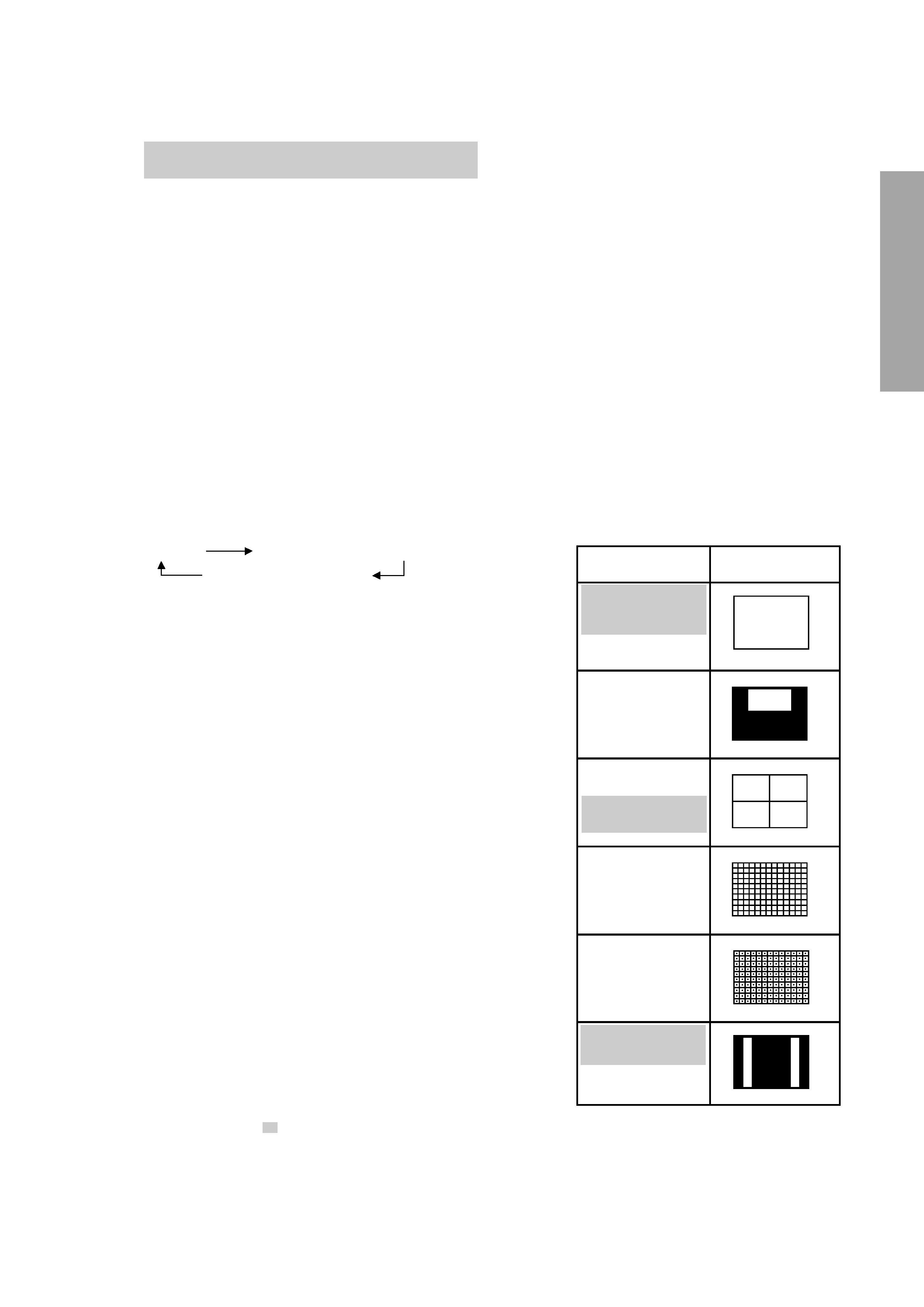
7. TEST SIGNAL SELECTION
1) Every pressing of a button on the Remote Control changes the built-in test patterns on screen as described
below in SERVICE MODE.
Signals
Picture
· Red raster
· Green raster
· Blue raster
· All Black
· All White
· Black & White
· Black cross-hatch
· White cross-hatch
· Black cross-dot
· White cross-dot
· Black cross-bar
· White cross-bar
· Black cross-bar
on green raster
· H signal (white)
· H signal (black)
* The signals marked with
are not usable to display in the Test signal for some model.
Signal off
NTSC signals (14 patterns)
PAL signals (14 patterns)