
FILE NO. 023-200214
SERVICE MANUAL
SUMMARY
N2PS Chassis
COLOR TELEVISION
PUBLISHED IN JAPAN,
Jul., 2002
So
36HF12
(TAC0131)
36HF12 is the same as 36HFX71 except for the parts tabled on back of this sheet.
Use this service manual together with the service manual of 36HFX71, 32HFX71 (File No. 020-
200116).
TOSHIBA CORPORATION
1-1, SHIBAURA 1-CHOME, MINATO-KU, TOKYO 105-8001, JAPAN
REPLACEMENT PARTS LIST DIFFERENCES
Location
No.
Part No.
Description
Location
No.
Part No.
Description
A211
23530412
Front Cover
A213
23428108
Door
A224
23445647
Button
A701
23064769
Carton
C673
24669100
EL, 10?F,
±20%, 50V
C678
24669100
EL, 10?F,
±20%, 50V
CA33
24100103
Chip, 0.01?F, +80%, -20%
CA95
24100103
Chip, 0.01?F, +80%, -20%
CA611
24100103
Chip, 0.01?F, +80%, -20%
CB90
24100103
Chip, 0.01?F, +80%, -20%
CD01
24797479
EL, 4.7?F,
±20%, 50V
CD15
24539104
PF, 0.1?F
CD17
24797479
EL, 4.7?F,
±20%, 50V
CD42
24797479
EL, 4.7?F,
±20%, 50V
CD44
24797479
EL, 4.7?F,
±20%, 50V
CD45
24503041
PF, 0.1?F, 63V
CD46
24567103
PF, 0.01?F
CD47
24797478
EL, 0.47?F,
±20%, 50V
CD48
24590472
PF, 4700pF
CD49
24797478
EL, 0.47?F,
±20%, 50V
CD60
24503041
PF, 0.1?F, 63V
CD61
24763221
EL, 220?F,
±20%, 16V
CD62
24232103
CD, 0.01?F, +80%, -20%
CD63
24762102
EL, 1000?F,
±20%, 10V
CD64
24797479
EL, 4.7?F,
±20%, 50V
CD65
24797100
EL, 10?F,
±20%, 50V
CD66
24797100
EL, 10?F,
±20%, 50V
CD70
24797100
EL, 10?F,
±20%, 50V
CD103
24797100
EL, 10?F,
±20%, 50V
CD107
24567823
PF, 0.082?F
CD123
24797100
EL, 10?F,
±20%, 50V
CD128
24797100
EL, 10?F,
±20%, 50V
CD129
24797100
EL, 10?F,
±20%, 50V
CD131
24797100
EL, 10?F,
±20%, 50V
K912
23306414
Remote Hand Unit, CT-90087
Q610
23906880
IC, TA8246AH
QD41
23000189
IC, TA2136N
R663
24011472
Chip, 4700 ohm, 1/20W
R664
24011472
Chip, 4700 ohm, 1/20W
R690
24011472
Chip, 4700 ohm, 1/20W
R691
24011472
Chip, 4700 ohm, 1/20W
RD41
24366102
CF, 1k ohm
RD42
24366432
CF, 4300 ohm
RD43
24366114
CF, 110k ohm
RD44
24366132
CF, 1300 ohm
RD45
24366473
CF, 47k ohm
RD46
24366513
CF, 51k ohm
RD47
24366392
CF, 3900 ohm
RD61
24366103
CF, 10k ohm
RD63
24366101
CF, 100 ohm
RD64
24366101
CF, 100 ohm
RD65
24366122
CF, 1200 ohm
RD66
24366821
CF, 820 ohm
RD67
24366152
CF, 1500 ohm
RD68
24366681
CF, 680 ohm
RD71
24366223
CF, 22k ohm
RD72
24366223
CF, 22k ohm
RD106
24366101
CF, 100 ohm
RD108
24366101
CF, 100 ohm
RD110
24366223
CF, 22k ohm
RD111
24366223
CF, 22k ohm
RD117
24366101
CF, 100 ohm
RD120
24366101
CF, 100 ohm
RS101
24011472
Chip, 4700 ohm, 1/20W
RS102
24011472
Chip, 4700 ohm, 1/20W
RS109
24011392
Chip, 3900 ohm, 1/20W
RS113
24011392
Chip, 3900 ohm, 1/20W
RS124
24011332
Chip, 3300 ohm, 1/20W
RS125
24011562
Chip, 5600 ohm, 1/20W
* U902
23786787
SIGNAL Board, PD0162B
* UD01
23786219
SRS-3D Board, PD0076A
W661
23351038
Speaker, SPK-1311, 60x120mm,
8 ohm
W662
23351038
Speaker, SPK-1311, 60x120mm,
8 ohm
TOSHIBA CORPORATION
1-1, SHIBAURA 1- CHOME, MINATO-KU, TOKYO 105-8001, JAPAN
FILE NO. 020-200116
SERVICE MANUAL
COLOR TELEVISION
N1PS Chassis
36HFX71, 32HFX71
PUBLISHED IN JAPAN.
Jul., 2001
So
(TAC0132)
(TAC0130)

2
GENERAL
ADJUSTMENTS
SPECIFIC
INFORMATIONS
TABLE OF CONTENTS
CHAPTER 1 GENERAL ADJUSTMENTS
SAFETY INSTRUCTIONS ........................................................................................................................................ 3
SET-UP ADJUSTMENT ............................................................................................................................................ 4
SERVICE MODE ...................................................................................................................................................... 8
ELECTRICAL ADJUSTMENTS .............................................................................................................................. 11
CIRCUIT CHECKS ................................................................................................................................................. 13
CHAPTER 2 SPECIFIC INFORMATIONS
SETTING & ADJUSTING DATA .............................................................................................................................. 14
LOCATION OF CONTROLS ................................................................................................................................... 15
PROGRAMMING CHANNEL MEMORY ................................................................................................................. 17
CIRCUIT BLOCK DIAGRAM .................................................................................................................................. 18
CHASSIS AND CABINET REPLACEMENT PARTS LIST ......................................................................................19
PC BOARDS BOTTOM VIEW ................................................................................................................................. 43
TERMINAL VIEW OF TRANSISTORS ................................................................................................................... 53
SPECIFICATIONS .................................................................................................................................................. 55
APPENDIX:
CIRCUIT DIAGRAM
3
GENERAL
ADJUSTMENTS
SPECIFIC
INFORMATIONS
CHAPTER 1 GENERAL ADJUSTMENTS
SAFETY INSTRUCTIONS
WARNING: BEFORE SERVICING THIS CHASSIS, READ THE "X-RAY RADIATION PRECAUTION", "SAFETY PRECAU-
TION" AND "PRODUCT SAFETY NOTICE" INSTRUCTIONS BELOW.
X-RAY RADIATION PRECAUTION
1. Excessive high voltage can produce potentially hazard-
ous X-RAY RADIATION. To avoid such hazards, the high
voltage must not be above the specified limit. The nominal
value of the high voltage of this receiver is (A) kV at zero
beam current (minimum brightness) under a 120V AC
power source. The high voltage must not, under any cir-
cumstances, exceed (B) kV.
Refer to table-1 for high voltage (A), (B).
(See SETTING & ADJUSTING DATA on page 14)
Each time a receiver requires servicing, the high voltage
should be checked following the HIGH VOLTAGE CHECK
procedure in this manual. It is recommended that the read-
ing of the high voltage be recorded as a part of the service
record. It is important to use an accurate and reliable high
voltage meter.
2. This receiver is equipped with a Fail Safe (FS) circuit which
prevents the receiver from producing an excessively high
voltage even if the B+ voltage increases abnormally. Each
time the receiver is serviced, the FS circuit must be checked
to determine that the circuit is properly functioning, follow-
ing the FS CIRCUIT CHECK procedure in this manual.
3. The only source of X-RAY RADIATION in this TV receiver
is the picture tube. For continued X-RAY RADIATION pro-
tection, the replacement tube must be exactly the same
type tube as specified in the parts list.
4. Some part in this receiver have special safety-related char-
acteristics for X-RAY RADIATION protection. For contin-
ued safety, parts replacement should be undertaken only
after referring to the PRODUCT SAFETY NOTICE below.
SAFETY PRECAUTION
Connect a 1500 ohm 10 watt resistor, paralleled by a 0.15
µF, AC type capacitor, between a known good earth ground
(water pipe, conduit, etc.) and the exposed metallic parts,
one at a time. Measure the AC voltage across the combi-
nation of 1500 ohm resistor and 0.15
µF capacitor. Re-
verse the AC plug at the AC outlet and repeat AC voltage
measurements for each exposed metallic part. Voltage
measured must not exceed 0.3 volts rms. This corresponds
to 0.2 milliamp. AC. Any value exceeding this limit consti-
tutes a potential shock hazard and must be corrected im-
mediately.
WARNING : Service should not be attempted by anyone unfa-
miliar with the necessary precautions on this receiver. The fol-
lowing are the necessary precautions to be observed before
servicing this chassis.
1. An isolation Transformer should be connected in the power
line between the receiver and the AC line before any serv-
ice is performed on the receiver.
2. Always discharge the picture tube anode to the CRT con-
ductive coating before handling the picture tube. The pic-
ture tube is highly evacuated and if broken, glass frag-
ments will be violently expelled. Use shatter proof gog-
gles and keep picture tube away from the unprotected body
while handling.
3. When replacing a chassis in the cabinet, always be cer-
tain that all the protective devices are put back in place,
such as; non-metallic control knobs, insulating covers,
shields, isolation resistor-capacitor network etc.
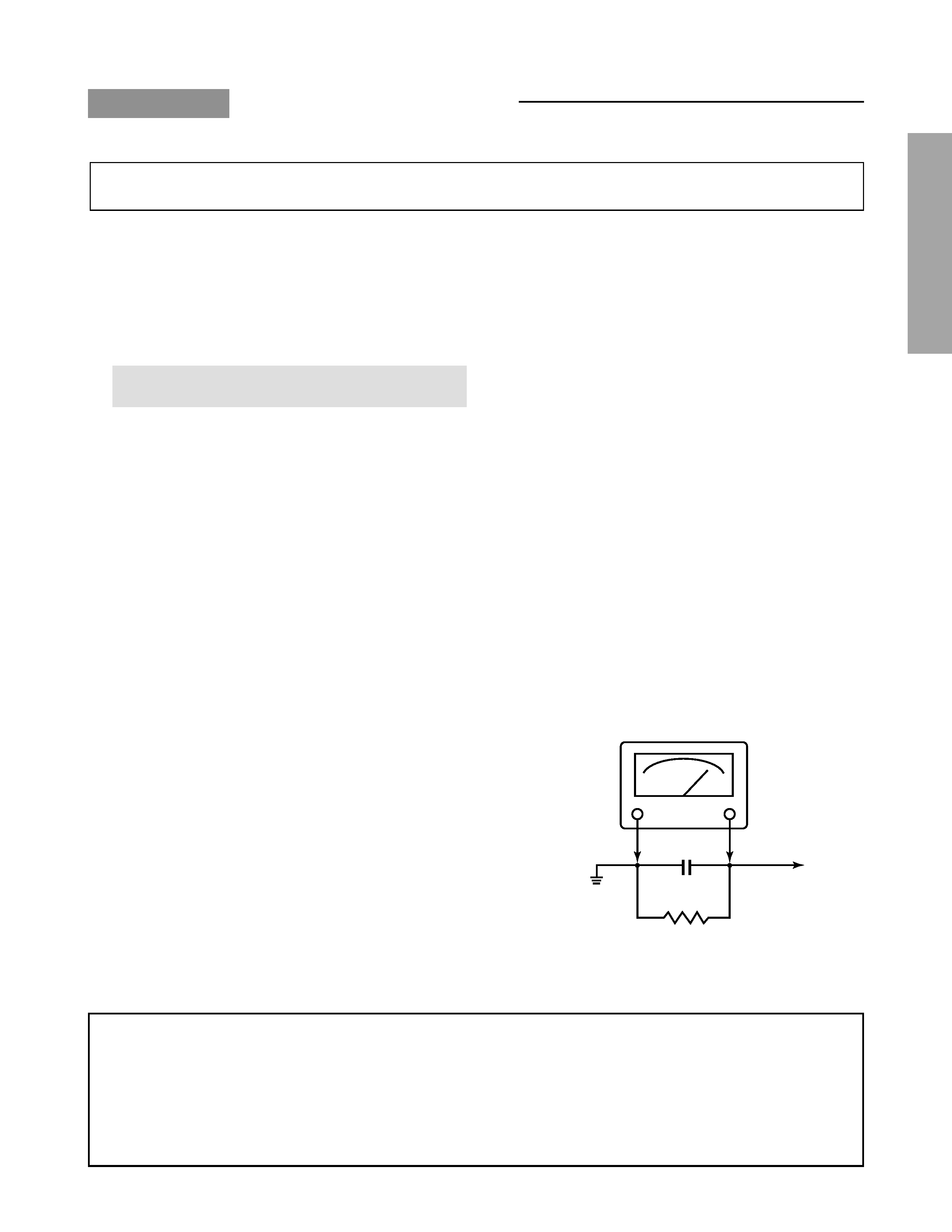
4. Before returning the set to the customer, always perform
an AC leakage current check on the exposed metallic parts
of the cabinet, such as antennas, terminals, screwheads,
metal overlays, control shafts etc. to be sure the set is
safe to operate without danger of electrical shock. Plug
the AC line cord directly into a 120V AC outlet (do not use
a line isolation transformer during this check). Use an AC
voltmeter having 5000 ohms per volt or more sensitivity in
the following manner:
AC VOLTMETER
0.15
µF
Good earth ground
such as a water
pipe, conduit, etc.
Place this probe on
each exposed
metallic part.
1500 ohm
10 watt
PRODUCT SAFETY NOTICE
Many electrical and mechanical parts in this chassis have special safety-related characteristics. These characteristics are
often passed unnoticed by a visual inspection and the protection afforded by them cannot necessarily be obtained by using
replacement components rated for higher voltage, wattage, etc. Replacement parts which have these special safety charac-
teristics are identified in this manual and its supplements; electrical components having such features are identified by the
international hazard symbols on the schematic diagram and the parts list.
Before replacing any of these components, read the parts list in this manual carefully. The use of substitute replacement
parts which do not have the same safety characteristics as specified in the parts list may create shock, fire, X-ray radiation
or other hazards.