SERVICE MANUAL
COLOR TELEVISION
DOCUMENT CREATED IN JAPAN, May, 2005
32AF45
32AF45C
(MFR'S VERSION A)
FILE NO. 050-200523
SERVICING NOTICES ON CHECKING
6. AVOID AN X-RAY
1. KEEP THE NOTICES
As for the places which need special attentions,
they are indicated with the labels or seals on the
cabinet, chassis and parts. Make sure to keep the
indications and notices in the operation manual.
3. USE THE DESIGNATED PARTS
5. TAKE CARE TO DEAL WITH THE
CATHODE-RAY TUBE
Safety is secured against an X-ray by consider-
ing about the cathode-ray tube and the high
voltage peripheral circuit, etc.
Therefore, when repairing the high voltage pe-
ripheral circuit, use the designated parts and
make sure not modify the circuit.
Repairing except indicates causes rising of high
voltage, and it emits an X-ray from the cathode-
ray tube.
Please include the following informations when you order parts. (Particularly the VERSION LETTER.)
1. MODEL NUMBER and VERSION LETTER
The MODEL NUMBER can be found on the back of each product and the VERSION LETTER can be
found at the end of the SERIAL NUMBER.
2. PART NO. and DESCRIPTION
You can find it in your SERVICE MANUAL.
HOW TO ORDER PARTS
When you exchange IC and Transistor with a heat sink, apply silicon grease on the contact section of
the heat sink. Befor applying new silicon grease, remove all the old silicon grease. (Old grease may
cause damages to the IC and Transistor.)
IMPORTANT
2. AVOID AN ELECTRIC SHOCK
There is a high voltage part inside. Avoid an
electric shock while the electric current is
flowing.
The parts in this equipment have the specific
characters of incombustibility and withstand
voltage for safety. Therefore, the part which is
replaced should be used the part which has
the same character.
Especially as to the important parts for safety
which is indicated in the circuit diagram or the
table of parts as a
mark, the designated
parts must be used.
4. PUT PARTS AND WIRES IN THE
ORIGINAL POSITION AFTER
ASSEMBLING OR WIRING
There are parts which use the insulation
material such as a tube or tape for safety, or
which are assembled in the condition that
these do not contact with the printed board.
The inside wiring is designed not to get closer
to the pyrogenic parts and high voltage parts.
Therefore, put these parts in the original
positions.
In the condition that an explosion-proof cathode-
ray tube is set in this equipment, safety is
secured against implosion. However, when
removing it or serving from backward, it is
dangerous to give a shock. Take enough care to
deal with it.
PERFORM A SAFETY CHECK AFTER
SERVICING
7.
Confirm that the screws, parts and wiring which
were removed in order to service are put in the
original positions, or whether there are the
portions which are deteriorated around the
serviced places serviced or not. Check the
insulation between the antenna terminal or
external metal and the AC cord plug blades.
And be sure the safety of that.
(INSULATION CHECK PROCEDURE)
1.
2.
3.
4.
Unplug the plug from the AC outlet.
Remove the antenna terminal on TV and turn
on the TV.
Insulation resistance between the cord plug
terminals and the eternal exposure metal
[Note 2] should be more than 1M ohm by
using the 500V insulation resistance meter
[Note 1].
If the insulation resistance is less than 1M
ohm, the inspection repair should be
required.
[Note 1]
If you have not the 500V insulation
resistance meter, use a Tester.
[Note 2]
External exposure metal: Antenna terminal
Headphone jack
A1-1
32AF45/32AF45C
Licensed by BBE Sound, Inc. under USP5510752 and 5736897.
BBE and BBE symbol are registered trademarks of BBE
Sound, Inc.
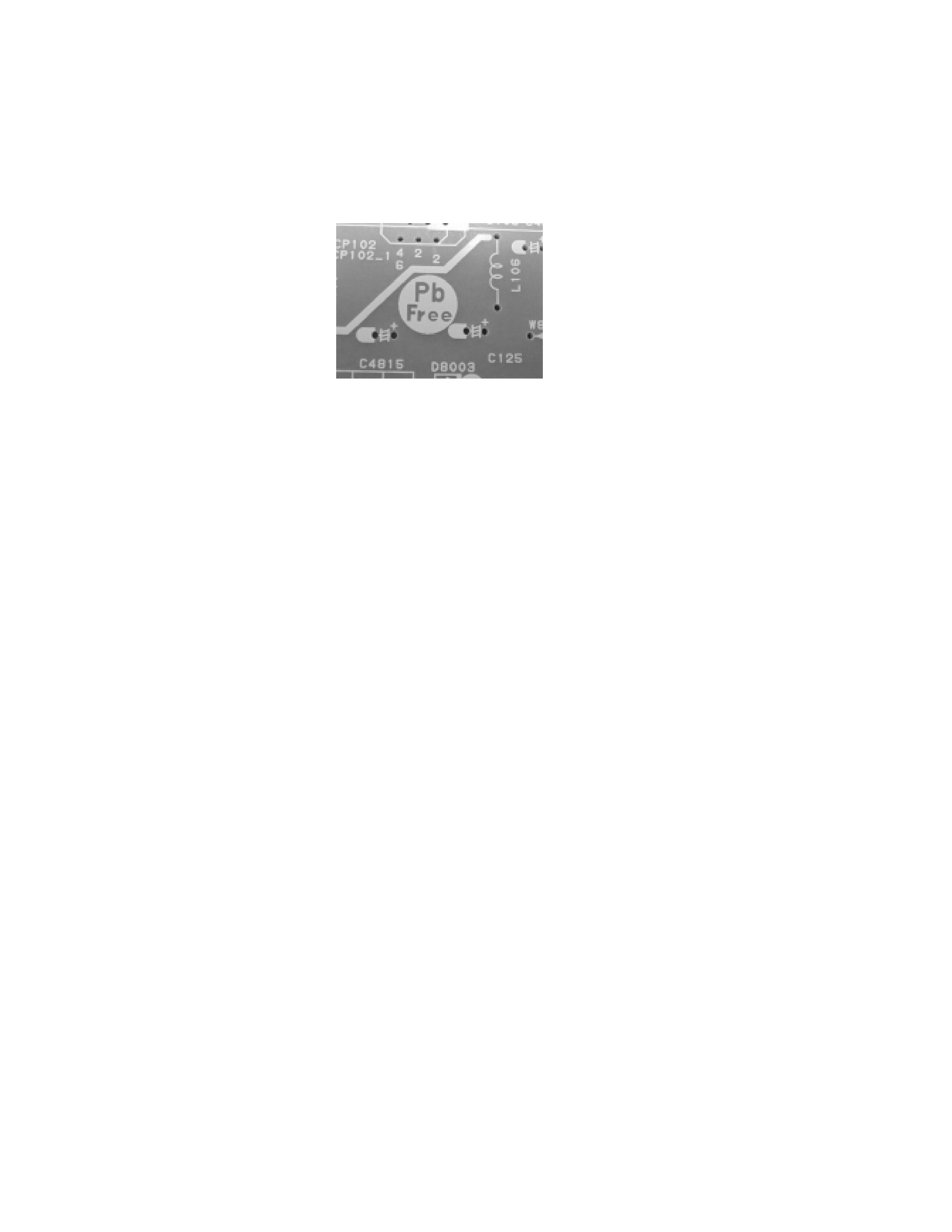
PCBs (manufactured) using lead free solder will have a PbF printing on the PCB.
(Please refer to figures.)
Caution:
Pb free solder has a higher melting point than standard solder;
Typically the melting point is 50
°F~70°F(30°C~40°C) higher.
Please use a soldering iron with temperature control and adjust it to 650
°F ± 20°F (350°C ± 10°C).
In case of using high temperature soldering iron, please be carefull not to heat too long.
Pb free solder will tend to splash when heated too high (about 1100
°F/ 600°C).
All products with the printed circuit board with PbF printing must be serviced with lead free solder.
When soldering or unsoldering, completely remove all of the solder from the pins or solder area,
and be sure to heat the soldering points with the lead free solder until it melts sufficiently.
Distinction of PbF PCB:
Recommendations
Recommended lead free solder composition is Sn-3.0Ag-0.5Cu.
ABOUT LEAD FREE SOLDER (PbF)
·
·
·
A1-2
32AF45/32AF45C

TABLE OF CONTENTS
SERVICING NOTICES ON CHECKING .....................................................................................
HOW TO ORDER PARTS ..........................................................................................................
IMPORTANT ...............................................................................................................................
ABOUT LEAD FREE SOLDER (PbF) ........................................................................................
TABLE OF CONTENTS ..............................................................................................................
GENERAL SPECIFICATIONS ...................................................................................................
DISASSEMBLY INSTRUCTIONS
1. REMOVAL OF ANODE CAP ...............................................................................................
2. REMOVAL AND INSTALLATION OF FLAT PACKAGE IC ................................................
SERVICE MODE LIST ................................................................................................................
CONFIRMATION OF HOURS USED .........................................................................................
WHEN REPLACING EEPROM (MEMORY) IC ..........................................................................
ELECTRICAL ADJUSTMENTS ..................................................................................................
BLOCK DIAGRAMS ...................................................................................................................
PRINTED CIRCUIT BOARDS
MAIN ........................................................................................................................................
CRT/POWER/STEREO JACK .................................................................................................
SCHEMATIC DIAGRAMS
MICON .....................................................................................................................................
CHROMA .................................................................................................................................
DEFLECTION ..........................................................................................................................
POWER ...................................................................................................................................
SOUND ....................................................................................................................................
TUNER/STEREO .....................................................................................................................
AV ............................................................................................................................................
COMB FILTER .........................................................................................................................
SUB POWER ...........................................................................................................................
CRT/SVM .................................................................................................................................
AV JACK ..................................................................................................................................
WAVEFORMS .............................................................................................................................
MECHANICAL EXPLODED VIEWS ...........................................................................................
MECHANICAL REPLACEMENT PARTS LIST .........................................................................
ELECTRICAL REPLACEMENT PARTS LIST ...........................................................................
A1-1
A1-1
A1-1
A1-2
A2-1
A3-1~A3-10
B1-1
B2-1, B2-2
C-1
C-1
C-1
D-1~D-6
E-1, E-2
F-1~F-4
F-5, F-6
G-1, G-2
G-3, G-4
G-5, G-6
G-7, G-8
G-9, G-10
G-11, G-12
G-13, G-14
G-15, G-16
G-17, G-18
G-19, G-20
G-21, G-22
H-1, H-2
I-1, I-2
J1-1, J1-2
J2-1~J2-10
A2-1
32AF45/32AF45C
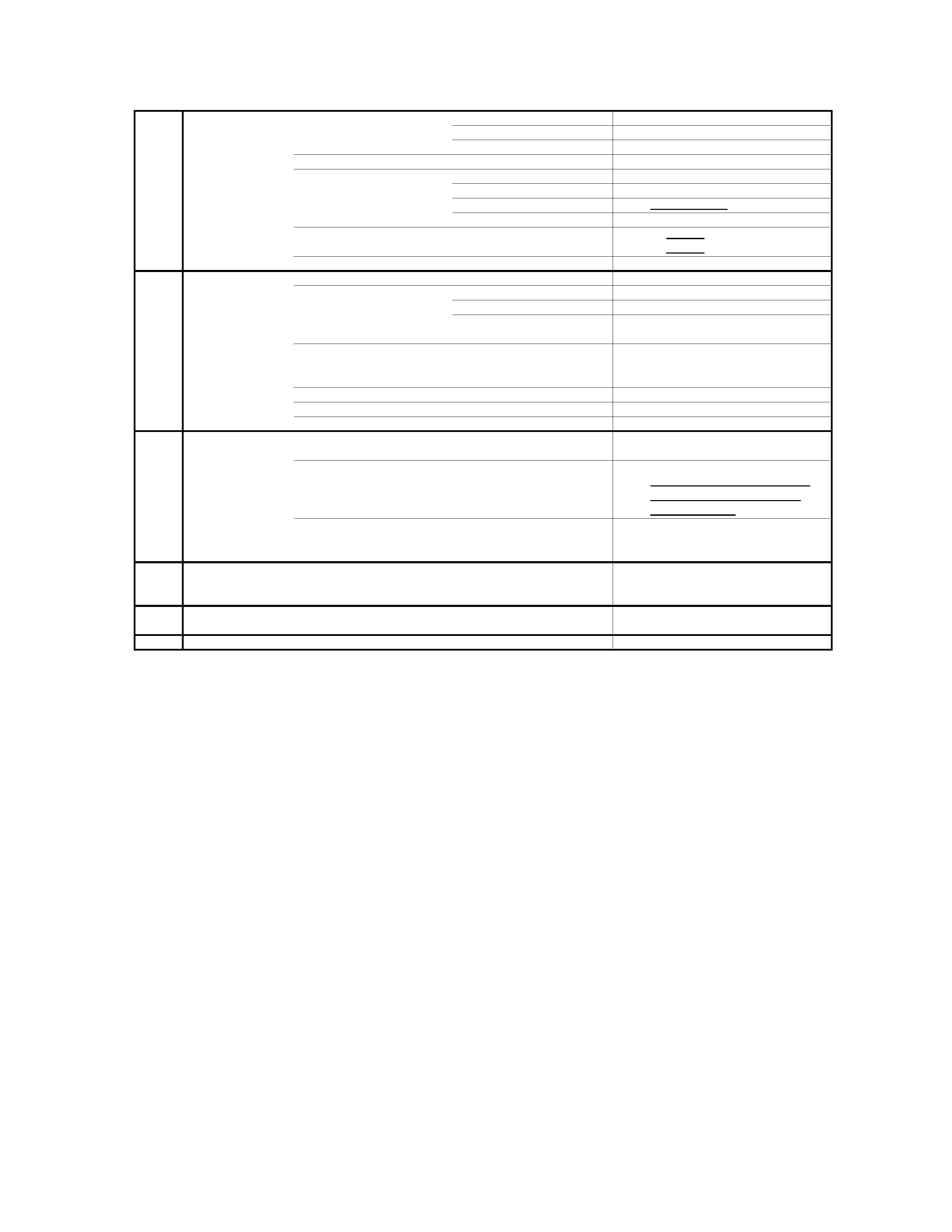
GENERAL SPECIFICATIONS
G-1
TV
CRT
CRT Size / Visual Size
32 inch / 802.0mmV
System
CRT Type
Flat
Magnetic Field
BV/BH
+0.45G/0.18G
Color System
NTSC
Speaker
2 Speaker
Position
Front
Size
2.0 x 4.7 Inch
Impedance
8
ohm
Sound Output
MAX
5.0+5.0 W
10%(Typical)
-
W
NTSC3.58+4.43 /PAL60Hz
No
G-2
Tuning
Broadcasting System
US
System M
System
Tuner and
System
1Tuner
Receive CH
Destination
USA(W/ CATV)
2 - 69, 4A, A-5 - A-1,
CH Coverage
A - I, J - W, W+1 - W+84
Intermediate
Picture(FP)
45.75MHz
Frequency
Sound(FS)
41.25MHz
FP-FS
4.50MHz
Preset CH
No
Stereo/Dual TV Sound
Yes
Tuner Sound Muting
Yes
G-3
Power
Power Source
AC
120V AC 60Hz
DC
Power Consumption
at AC
137 W at AC 120 V 60 Hz
Stand by (at AC)
3
W at AC 120 V 60 Hz
Per Year
--
kWh/Year
Protector
Power Fuse
Yes
Safety Circuit
Yes
IC Protector(Micro Fuse)
No
G-4
Regulation
Safety
UL
Radiation
FCC
X-Radiation
DHHS
G-5
Temperature
Operation
+5oC ~ +40oC
Storage
-20oC ~ +60oC
G-6
Operating Humidity
Less than 80% RH
A3-1
32AF45