TOSHIBA CORPORATION
1-1, SHIBAURA 1- CHOME, MINATO-KU, TOKYO 105-8001, JAPAN
FILE NO. 020-200210
SERVICE MANUAL
COLOR TELEVISION
N2F Chassis
32AF62, 32AF42
PUBLISHED IN JAPAN,
Jul. 2002
So
(TAC0210)
(TAC0211)

2
GENERAL
ADJUSTMENTS
SPECIFIC
INFORMATIONS
TABLE OF CONTENTS
CHAPTER 1 GENERAL ADJUSTMENTS
SAFETY INSTRUCTIONS ........................................................................................................................................ 3
SET-UP ADJUSTMENT ............................................................................................................................................ 4
SERVICE MODE ...................................................................................................................................................... 8
DESIGN MODE ...................................................................................................................................................... 11
ELECTRICAL ADJUSTMENT ................................................................................................................................ 12
CIRCUIT CHECKS ................................................................................................................................................. 15
CHAPTER 2 SPECIFIC INFORMATIONS
SETTING & ADJUSTING DATA .............................................................................................................................. 16
LOCATION OF CONTROLS ................................................................................................................................... 17
PROGRAMMING CHANNEL MEMORY ................................................................................................................. 19
CHASSIS AND CABINET REPLACEMENT PARTS LIST ......................................................................................20
PC BOARDS BOTTOM VIEW ................................................................................................................................. 31
TERMINAL VIEW OF TRANSISTORS ................................................................................................................... 39
CIRCUIT BLOCK DIAGRAM .................................................................................................................................. 42
SPECIFICATIONS .............................................................................................................................................. END
APPENDIX:
CIRCUIT DIAGRAM
3
GENERAL
ADJUSTMENTS
SPECIFIC
INFORMATIONS
SAFETY INSTRUCTIONS
WARNING: BEFORE SERVICING THIS CHASSIS, READ THE "X-RAY RADIATION PRECAUTION", "SAFETY PRECAU-
TION" AND "PRODUCT SAFETY NOTICE" INSTRUCTIONS BELOW.
X-RAY RADIATION PRECAUTION
1. Excessive high voltage can produce potentially hazardous
X-RAY RADIATION.To avoid such hazards, the high voltage
must not be above the specified limit. The nominal value of
the high voltage of this receiver is (A) kV at zero beam
current (minimum brightness) under a 120V AC power
source. The high voltage must not, under any circum-
stances, exceed (B) kV.
Refer to table-1 for high voltage (A), (B).
(See SETTING & ADJUSTING DATA on page 16)
Each time a receiver requires servicing, the high voltage
should be checked following the HIGH VOLTAGE CHECK
procedure in this manual. It is recommended that the read-
ing of the high voltage be recorded as a part of the service
record. It is important to use an accurate and reliable high
voltage meter.
2. This receiver is equipped with a Fail Safe (FS) circuit which
prevents the receiver from producing an excessively high
voltage even if the B+ voltage increases abnormally. Each
time the receiver is serviced, the FS circuit must be checked
to determine that the circuit is properly functioning, follow-
ing the FS CIRCUIT CHECK procedure in this manual.
3. The only source of X-RAY RADIATION in this TV receiver
is the picture tube. For continued X-RAY RADIATION pro-
tection, the replacement tube must be exactly the same
type tube as specified in the parts list.
4. Some part in this receiver have special safety-related char-
acteristics for X-RAY RADIATION protection. For contin-
ued safety, parts replacement should be undertaken only
after referring to the PRODUCT SAFETY NOTICE below.
SAFETY PRECAUTION
Connect a 1500 ohm 10 watt resistor, paralleled by a 0.15
µF, AC type capacitor, between a known good earth ground
(water pipe, conduit, etc.) and the exposed metallic parts,
one at a time. Measure the AC voltage across the combi-
nation of 1500 ohm resistor and 0.15
µF capacitor. Re-
verse the AC plug at the AC outlet and repeat AC voltage
measurements for each exposed metallic part. Voltage
measured must not exceed 0.3 volts rms. This corresponds
to 0.2 milliamp. AC. Any value exceeding this limit consti-
tutes a potential shock hazard and must be corrected im-
mediately.
WARNING : Service should not be attempted by anyone unfa-
miliar with the necessary precautions on this receiver. The fol-
lowing are the necessary precautions to be observed before
servicing this chassis.
1. An isolation Transformer should be connected in the power
line between the receiver and the AC line before any serv-
ice is performed on the receiver.
2. Always discharge the picture tube anode to the CRT con-
ductive coating before handling the picture tube. The pic-
ture tube is highly evacuated and if broken, glass frag-
ments will be violently expelled. Use shatter proof gog-
gles and keep picture tube away from the unprotected body
while handling.
3. When replacing a chassis in the cabinet, always be cer-
tain that all the protective devices are put back in place,
such as; non-metallic control knobs, insulating covers,
shields, isolation resistor-capacitor network etc.
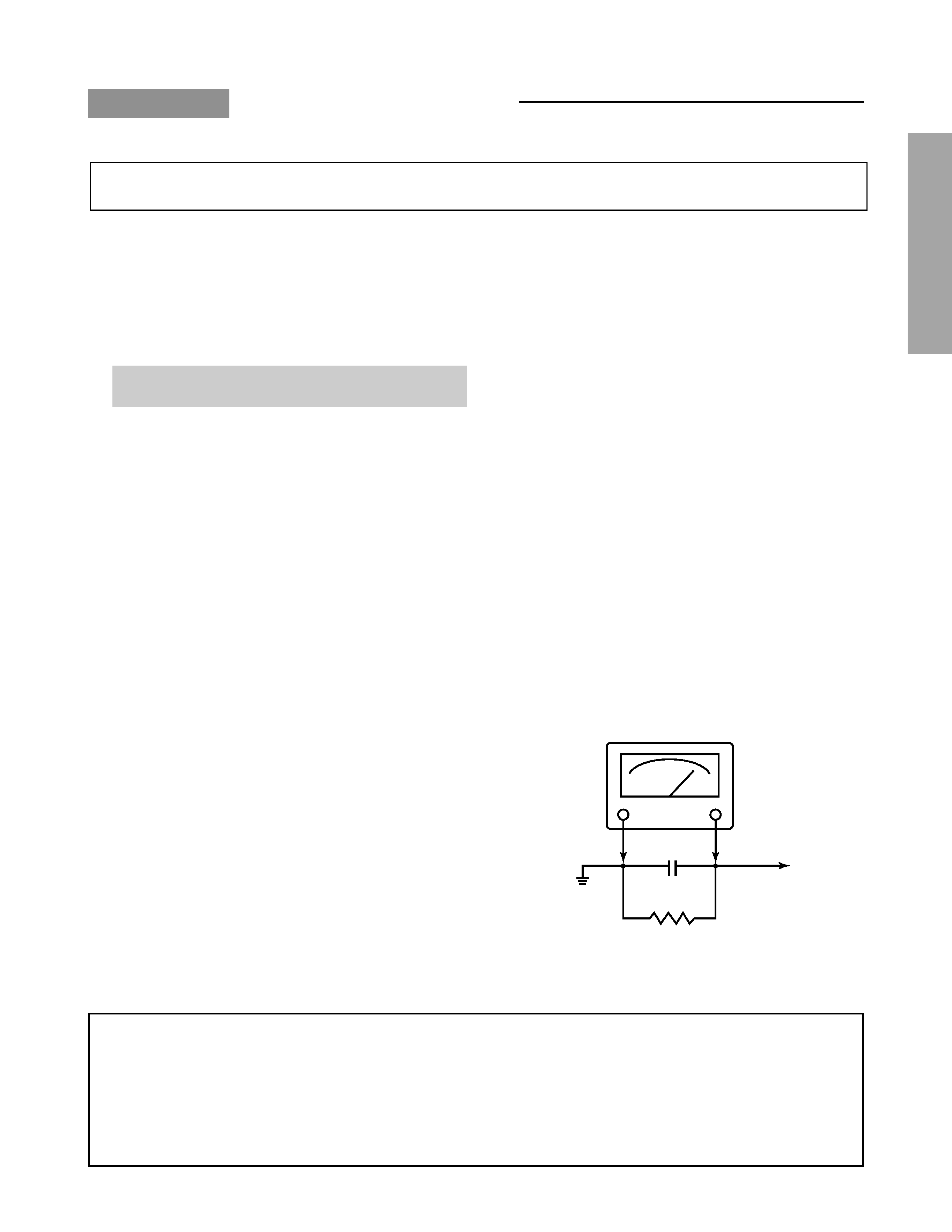
4. Before returning the set to the customer, always perform
an AC leakage current check on the exposed metallic parts
of the cabinet, such as antennas, terminals, screwheads,
metal overlays, control shafts etc. to be sure the set is
safe to operate without danger of electrical shock. Plug
the AC line cord directly into a 120V AC outlet (do not use
a line isolation transformer during this check). Use an AC
voltmeter having 5000 ohms per volt or more sensitivity in
the following manner:
AC VOLTMETER
0.15
µF
Good earth ground
such as a water
pipe, conduit, etc.
Place this probe on
each exposed
metallic part.
1500 ohm
10 watt
PRODUCT SAFETY NOTICE
Many electrical and mechanical parts in this chassis have special safety-related characteristics. These characteristics are
often passed unnoticed by a visual inspection and the protection afforded by them cannot necessarily be obtained by using
replacement components rated for higher voltage, wattage, etc. Replacement parts which have these special safety char-
acteristics are identified in this manual and its supplements; electrical components having such features are identified by
the international hazard symbols on the schematic diagram and the parts list.
Before replacing any of these components, read the parts list in this manual carefully. The use of substitute replacement
parts which do not have the same safety characteristics as specified in the parts list may create shock, fire, X-ray
radiation or other hazards.
CHAPTER 1 GENERAL ADJUSTMENTS
4
GENERAL
ADJUSTMENTS
SPECIFIC
INFORMATIONS
WARNING: BEFORE SERVICING THIS CHASSIS, READ THE "X-RAY RADIATION PRECAUTION", "SAFETY PRECAU-
TION" AND "PRODUCT SAFETY NOTICE" ON PAGE 3 OF THIS MANUAL.
SET-UP ADJUSTMENT (FOR 13", 14", 19", 20")
s The following adjustments should be made when a complete realignment is required or a new picture tube is installed.
Perform the adjustments in order as follows :
1. Color Purity
2. Convergence
3. White Balance
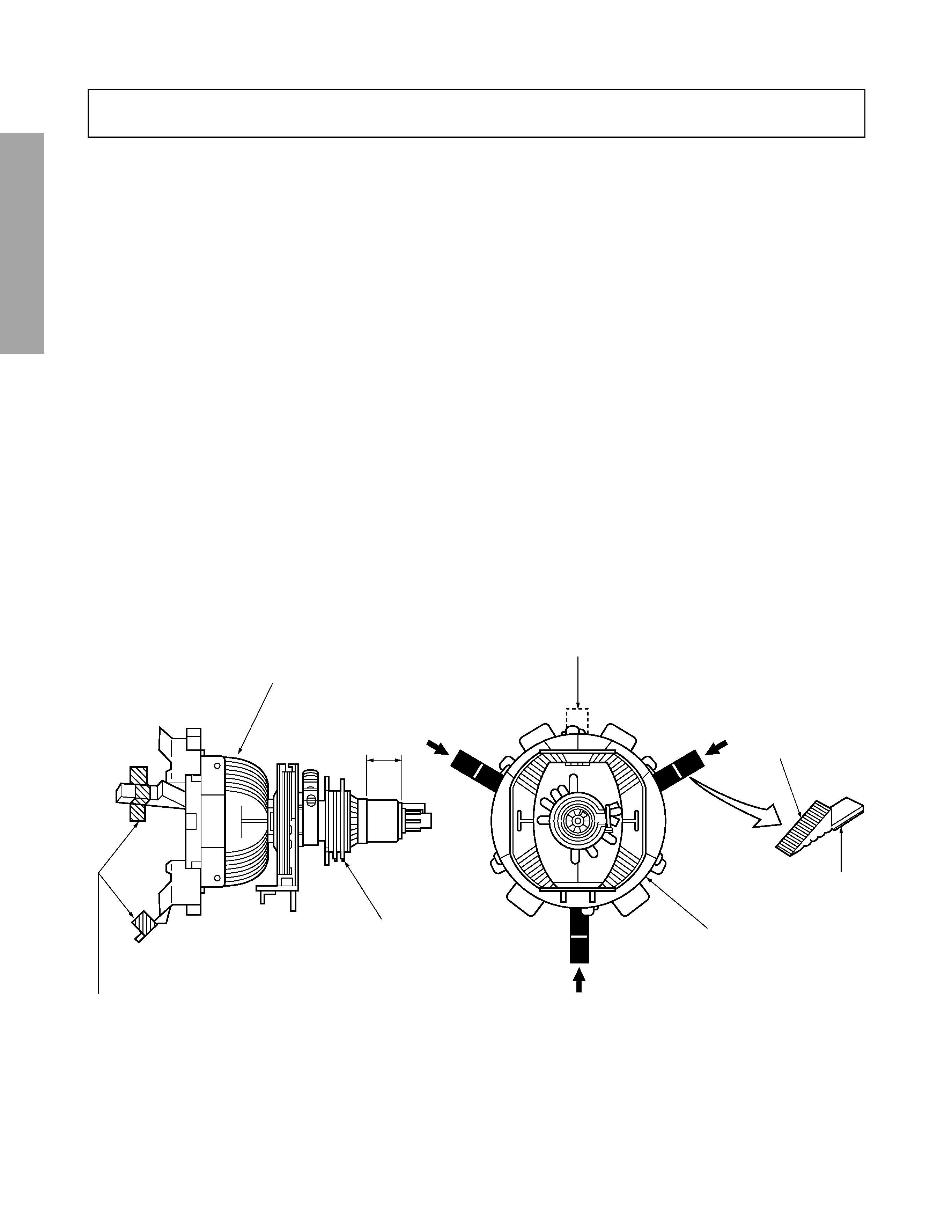
Note: The PURITY/CONVERGENCE MAGNET assembly and rubber wedges need mechanical positioning.
Refer to figure 1.
Mounting position of the purity magnet assembly should fit to same position as old one because slightly difference to
the position depend on a kind of tube.
* There are no adjustment of purity and convergence in some picture tube (Unified with purity magnet)
GLASS CLOTH
TAPES
DEFLECTION
YOKE
TEMPORARY
MOUNTING
RUBBER WEDGE
ADHESIVE
DEFLECTION
YOKE
PURITY/
CONVERGENCE
MAGNET ASS'Y
14mm(13", 14")
19mm(19", 20")
Figure 1.
COLOR PURITY ADJUSTMENT
NOTE : Before attempting any purity adjustments, the receiver
should be operated for at least fifteen minutes.
1. Demagnetize the picture tube and cabinet using a degauss-
ing coil.
2. Set the brightness and contrast to maximum.
3. Use a green raster from among the built-in test signals.
4. Loosen the clamp screw holding the yoke and slide the
yoke backward or forward to provide vertical green belt
(zone) in the picture screen.
5. Remove the Rubber Wedges.
6. Rotate and spread the tabs of the purity magnet (See fig-
ure 2.) around the neck of the picture tube until the green
belt is in the center of the screen. At the same time, enter
the raster vertically.
7. Slowly move the yoke forward or backward until a uniform
green screen is obtained. Tighten the clamp screw of the
yoke temporarily.
8. Check the purity of the red and blue raster.
5
GENERAL
ADJUSTMENTS
SPECIFIC
INFORMATIONS
CONVERGENCE ADJUSTMENTS
NOTE: Before attempting any convergence adjustments, the
receiver should be operated for at least fifteen min-
utes.
s
CENTER CONVERGENCE ADJUSTMENT
1. Use the cross-dot pattern from among the built-in test sig-
nals.
2. Set the brightness and contrast for well defined pattern.
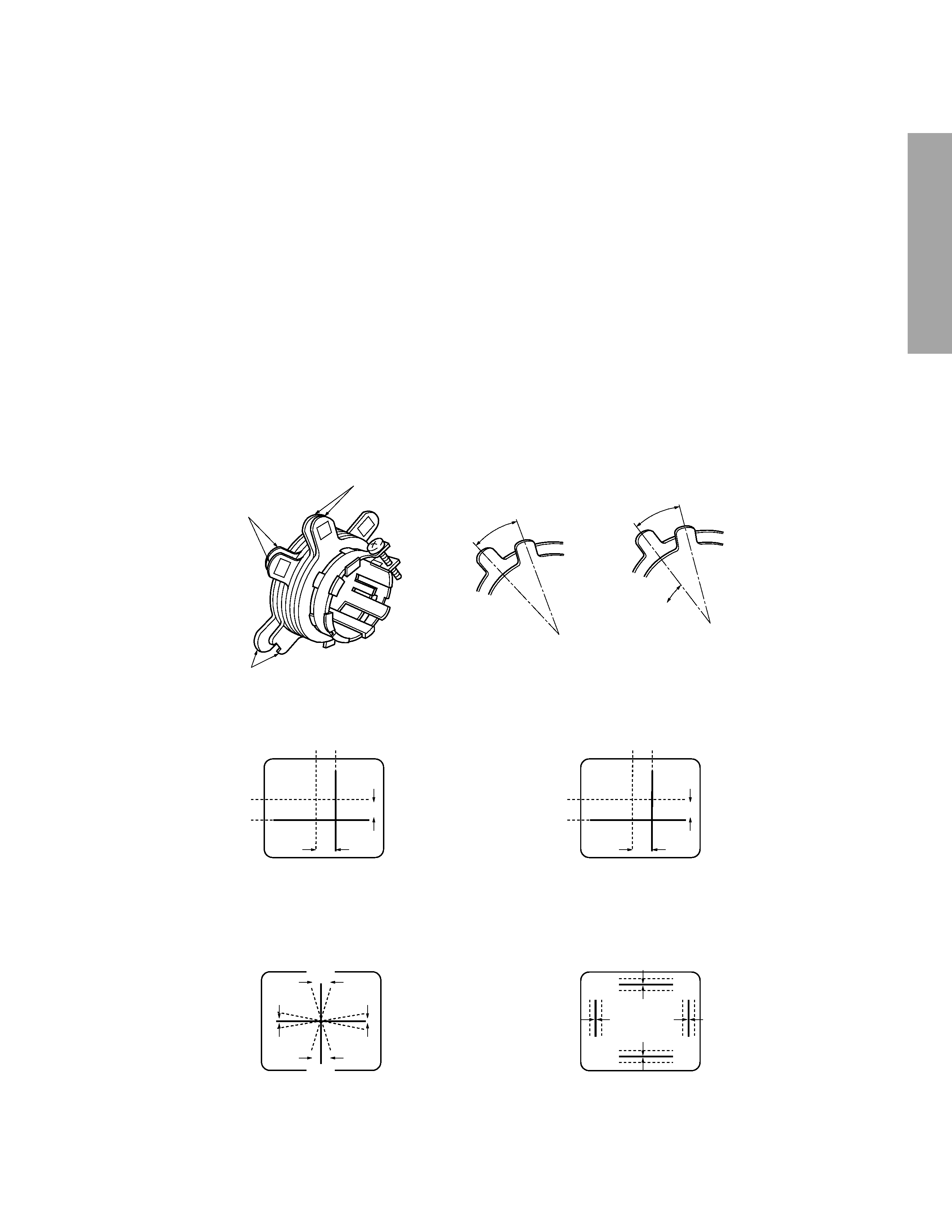
3. Adjust two tabs of the 4-Pole Magnets to change the an-
gle between them (See figure 2.) and superimpose red
and blue vertical lines in the center area of the picture
screen.
4. Turn the both tabs at the same time keeping the angle
constant to superimpose red and blue horizontal lines at
the center of the screen.
5. Adjust two tabs of 6-Pole Magnets to superimpose red/
blue line and green one. Adjusting the angle affects the
vertical lines and rotating both magnets affects the hori-
zontal lines.
6. Repeat adjustments 3, 4, 5 keeping in mind red, green
and blue movement, because 4-Pole Magnets and 6-Pole
Magnets have mutual interaction and make dot movement
complex.
s
CIRCUMFERENCE CONVERGENCE ADJUSTMENT
1. Loosen the clamping screw of deflection yoke slightly to
allow the yoke to tilt.
2. Temporarily put a wedge as shown in figure 1. (Do not
remove cover paper on adhesive part of the wedge.)
3. Tilt front of the deflection yoke up or down to obtain better
convergence in circumference. (See figure 3.) Push the
mounted wedge into the space between picture tube and
the yoke to fix the yoke temporarily.
4. Put other wedge into bottom space and remove the cover
paper to stick.
5. Tilt front of the yoke right or left to obtain better conver-
gence in circumference. (See figure 3.)
6. Keep the yoke position and put another wedge in either
upper space. Remove cover paper and stick the wedge
on picture tube to fix the yoke.
7. Detach the temporarily mounted wedge and put it in an-
other upper space. Stick it on picture tube to fix the yoke.
8. After fixing three wedges, recheck overall convergence.
Tighten the screw firmly to fix the yoke and check the yoke
is firm.
9. Stick three adhesive tapes on wedges as shown in figure
1.
Figure 2.
BLU
RED
BLU
RED
RED/BLU GRN
RED/BLU
GRN
B
G
R
R
G
B
BGR
RGB
BGR
RGB
R
G
B
B
G
R
4-POLE MAGNETS MOVEMENT
INCLINE THE YOKE UP (OR DOWN)
6-POLE MAGNETS MOVEMENT
Center Convergence by Convergence Magnets
Circumference Convergence by DEF Yoke
INCLINE THE YOKE RIGHT (OR LEFT)
Figure 3. Dot Movement Pattern
4-POLE
MAGNETS
PURITY
MAGNETS
6-POLE
MAGNETS
ADJUST THE ANGLE
(VERTICAL LINES)
FIXED
ROTATE TWO TABS
AT THE SAME TIME
(HORIZONTAL LINES)
CONVERGENCE MAGNET ASSEMBLY
ADJUSTMENT OF MAGNETS