
SERVICE MANUAL
SUMMARY
N0ES Chassis
27A40
COLOR TELEVISION
(TAC0015)
27A40 is the same as 27A50 except for the parts tabled on back of this sheet.
Use this service manual together with the service manual of 27A50 (File No. 020-200004).
PUBLISHED IN JAPAN, May., 2000
S
FILE NO. 023-200009

REPLACEMENT PARTS LIST DIFFERENCES
Location
No.
Part No.
Description
A201
23549910
Front Cover
A221
23104042
Lens
A222
23104045
Filter
A223
23445381
Button, Power
A224
23445382
Button, Control
A401
23005253
Back Cover
A703
23935360
Packing, Top
A708
23935361
Packing, Bottom
K912
23306316
Remote Hand Unit, CT-9995
Q503
23114528
Transistor, 2SC1740S, Q
R201
24366102
CF, 1k ohm
R202
24366102
CF, 1k ohm
R508
24366102
CF, 1k ohm
R509
24366102
CF, 1k ohm
R510
24366471
CF, 470 ohm
* U902
Main Board, PB9549B
W661
23151225
Speaker, SPK-1228,
60X90mm, 8 ohm
W662
23151225
Speaker, SPK-1228,
60X90mm, 8 ohm
Y101
23563899
Owner's Manual, English,
27A40
Y101F
23563900
Owner's Manual, French,
27A40
TOSHIBA CORPORATION
1-1, SHIBAURA 1-CHOME, MINATO-KU, TOKYO 105-8001, JAPAN
TOSHIBA CORPORATION
1-1, SHIBAURA 1- CHOME, MINATO-KU, TOKYO 105-8001, JAPAN
FILE NO. 020-200004
SERVICE MANUAL
COLOR TELEVISION
N0ES Chassis
27A50
PRINTED IN U.S.A.
Apr., 2000
U
(TAC0012)

2
GENERAL
ADJUSTMENTS
SPECIFIC
INFORMATIONS
TABLE OF CONTENTS
CHAPTER 1 GENERAL ADJUSTMENTS
SAFETY INSTRUCTIONS ........................................................................................................................................ 3
SET-UP ADJUSTMENT ............................................................................................................................................ 4
SERVICE MODE ...................................................................................................................................................... 8
DESIGN MODE ...................................................................................................................................................... 11
ELECTRICAL ADJUSTMENTS .............................................................................................................................. 12
CIRCUIT CHECKS ................................................................................................................................................. 16
CHAPTER 2 SPECIFIC INFORMATIONS
SETTING & ADJUSTING DATA ............................................................................................................................. 17
LOCATION OF CONTROLS ................................................................................................................................... 18
PROGRAMMING CHANNEL MEMORY ................................................................................................................. 20
CIRCUIT BLOCK DIAGRAM .................................................................................................................................. 21
CHASSIS AND CABINET REPLACEMENT PARTS LIST ......................................................................................22
PC BOARDS BOTTOM VIEW ................................................................................................................................ 31
TERMINAL VIEW OF TRANSISTORS ................................................................................................................... 34
SPECIFICATIONS .................................................................................................................................................. 37
APPENDIX:
CIRCUIT DIAGRAM
3
GENERAL
ADJUSTMENTS
SPECIFIC
INFORMATIONS
CHAPTER 1 GENERAL ADJUSTMENTS
SAFETY INSTRUCTIONS
WARNING: BEFORE SERVICING THIS CHASSIS, READ THE "X-RAY RADIATION PRECAUTION", "SAFETY PRECAU-
TION" AND "PRODUCT SAFETY NOTICE" INSTRUCTIONS BELOW.
X-RAY RADIATION PRECAUTION
1. Excessive high voltage can produce potentially hazard-
ous X-RAY RADIATION. To avoid such hazards, the high
voltage must not be above the specified limit. The nominal
value of the high voltage of this receiver is (A) kV at zero
beam current (minimum brightness) under a 120V AC
power source. The high voltage must not, under any cir-
cumstances, exceed (B) kV.
Refer to table-1 for high voltage (A), (B).
(See SETTING & ADJUSTING DATA on page 17.)
Each time a receiver requires servicing, the high voltage
should be checked following the HIGH VOLTAGE CHECK
procedure in this manual. It is recommended that the read-
ing of the high voltage be recorded as a part of the service
record. It is important to use an accurate and reliable high
voltage meter.
2. This receiver is equipped with a Fail Safe (FS) circuit which
prevents the receiver from producing an excessively high
voltage even if the B+ voltage increases abnormally. Each
time the receiver is serviced, the FS circuit must be checked
to determine that the circuit is properly functioning, follow-
ing the FS CIRCUIT CHECK procedure in this manual.
3. The only source of X-RAY RADIATION in this TV receiver
is the picture tube. For continued X-RAY RADIATION pro-
tection, the replacement tube must be exactly the same
type tube as specified in the parts list.
4. Some part in this receiver have special safety-related char-
acteristics for X-RAY RADIATION protection. For contin-
ued safety, parts replacement should be undertaken only
after referring to the PRODUCT SAFETY NOTICE below.
SAFETY PRECAUTION
Connect a 1500 ohm 10 watt resistor, paralleled by a 0.15
µF, AC type capacitor, between a known good earth ground
(water pipe, conduit, etc.) and the exposed metallic parts,
one at a time. Measure the AC voltage across the combi-
nation of 1500 ohm resistor and 0.15 µF capacitor. Re-
verse the AC plug at the AC outlet and repeat AC voltage
measurements for each exposed metallic part. Voltage
measured must not exceed 0.3 volts rms. This corresponds
to 0.2 milliamp. AC. Any value exceeding this limit consti-
tutes a potential shock hazard and must be corrected im-
mediately.
WARNING : Service should not be attempted by anyone unfa-
miliar with the necessary precautions on this receiver. The fol-
lowing are the necessary precautions to be observed before
servicing this chassis.
1. An isolation transformer should be connected in the power
line between the receiver and the AC line before any serv-
ice is performed on the receiver.
2. Always discharge the picture tube anode to the CRT con-
ductive coating before handling the picture tube. The pic-
ture tube is highly evacuated and if broken, glass frag-
ments will be violently expelled. Use shatter proof gog-
gles and keep picture tube away from the unprotected body
while handling.
3. When replacing a chassis in the cabinet, always be cer-
tain that all the protective devices are put back in place,
such as; non-metallic control knobs, insulating covers,
shields, isolation resistor-capacitor network, etc.
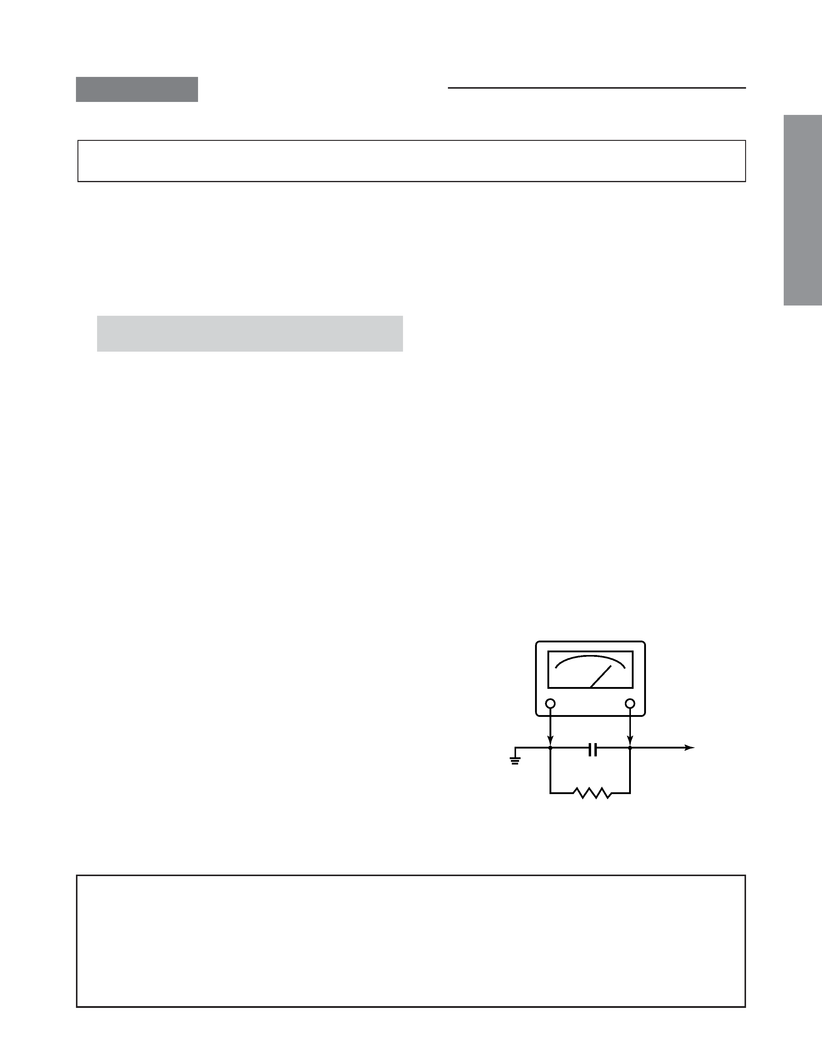
4. Before returning the set to the customer, always perform
an AC leakage current check on the exposed metallic parts
of the cabinet, such as antennas, terminals, screwheads,
metal overlays, control shafts, etc. to be sure the set is
safe to operate without danger of electrical shock. Plug
the AC line cord directly into a 120V AC outlet (do not use
a line isolation transformer during this check). Use an AC
voltmeter having 5000 ohms per volt or more sensitivity in
the following manner:
AC VOLTMETER
0.15
µF
Good earth ground
such as a water
pipe, conduit, etc.
Place this probe on
each exposed
metallic part.
1500 ohm
10 watt
PRODUCT SAFETY NOTICE
Many electrical and mechanical parts in this chassis have special safety-related characteristics. These characteristics are
often passed unnoticed by a visual inspection and the protection afforded by them cannot necessarily be obtained by using
replacement components rated for higher voltage, wattage, etc. Replacement parts which have these special safety char-
acteristics are identified in this manual and its supplements; electrical components having such features are identified by
the international hazard symbols on the schematic diagram and the parts list.
Before replacing any of these components, read the parts list in this manual carefully. The use of substitute replacement
parts which do not have the same safety characteristics as specified in the parts list may create shock, fire, X-ray radiation
or other hazards.