
- 1 -
SERVICE MANUAL
LCD Color Television
23HL85
FILE NO. 050-200531
Published in Japan, Sep. 2005 (YC)
TOSHIBA CORPORATION 2005
- 57 -
MODEL : 23HL85
8. SCHEMATIC DIAGRAM
TUNER/PC ......................................................................................................................................................... 1/16
VCTI .................................................................................................................................................................... 2/16
INPUT ................................................................................................................................................................. 3/16
3D COMB ............................................................................................................................................................ 4/16
ADC (COMP) ...................................................................................................................................................... 5/16
SIL9021 .............................................................................................................................................................. 6/16
FLI2300 ............................................................................................................................................................... 7/16
SWITCH .............................................................................................................................................................. 8/16
SWITCH&BUFFER ............................................................................................................................................. 9/16
AUDIO AMP ...................................................................................................................................................... 10/16
SCALER ........................................................................................................................................................... 11/16
POWER IN&INTERFACE .................................................................................................................................. 12/16
POWER ............................................................................................................................................................. 13/16
LED&IR ............................................................................................................................................................. 14/16
KEY ................................................................................................................................................................... 15/16
SIDE .................................................................................................................................................................. 16/16
SCHEMATIC DIAGRAM STRUCTURE:
WARNING : BEFORE SERVICING THIS CHASSIS, READ THE "SERVICE SAFETY PRECAUTIONS" ON PAGE 3 OF
THIS MANUAL.
CAUTION : The international hazard symbols "
" in the schematic diagram and the parts list designate components
which have special characteristics important for safety and should be replaced only with types identical to those in the
original circuit or specified in the parts list. The mounting position of replacements is to be identical with originals. Before
replacing any of these components, read carefully the SERVICE SAFETY PRECAUTIONS on the MANUAL for this
model. Do not degrade the safety of the receiver through improper servicing.
NOTE:
1. RESISTOR
Resistance is shown in ohm [K = 1.000, M = 1.000.000]. All resistors are 1/6W and 5%
tolerance carbon resistor, unless otherwise noted as the following marks.
1/2R = Metal or Metal oxide of 1/2 watt
1/2S = Carbon compsistion of 1/2 watt
1RF = Fuse resistor of 1 watt
10W = Cement of 10 watt
K =
±10%
G =
±2%
F =
±1%
2. CAPACITOR
Unless otherwise noted in schematic, all capacitor values less than 1 are expressed in
?F, and the values more than 1 in pF.
All capacitors are ceramic 50V, unless otherwise noted as the following marks.
Electolytic capacitor
Mylar capacitor
3. The parts indicated with "
* " have special characteristics, and should be replaced with identical parts only.
4. Voltages read with DIGITAL MULTI-METER from point indicated to chassing ground, using a color bar signal with all
controls at normal, line voltage 220 volts.
5. Waveforms are taken receiving color bar signal with enough sensitivity.
6. Voltage reading shown are nominal values and may vary
±20% except H.V.
* The information contained in this section subjects to model.
- 58 -
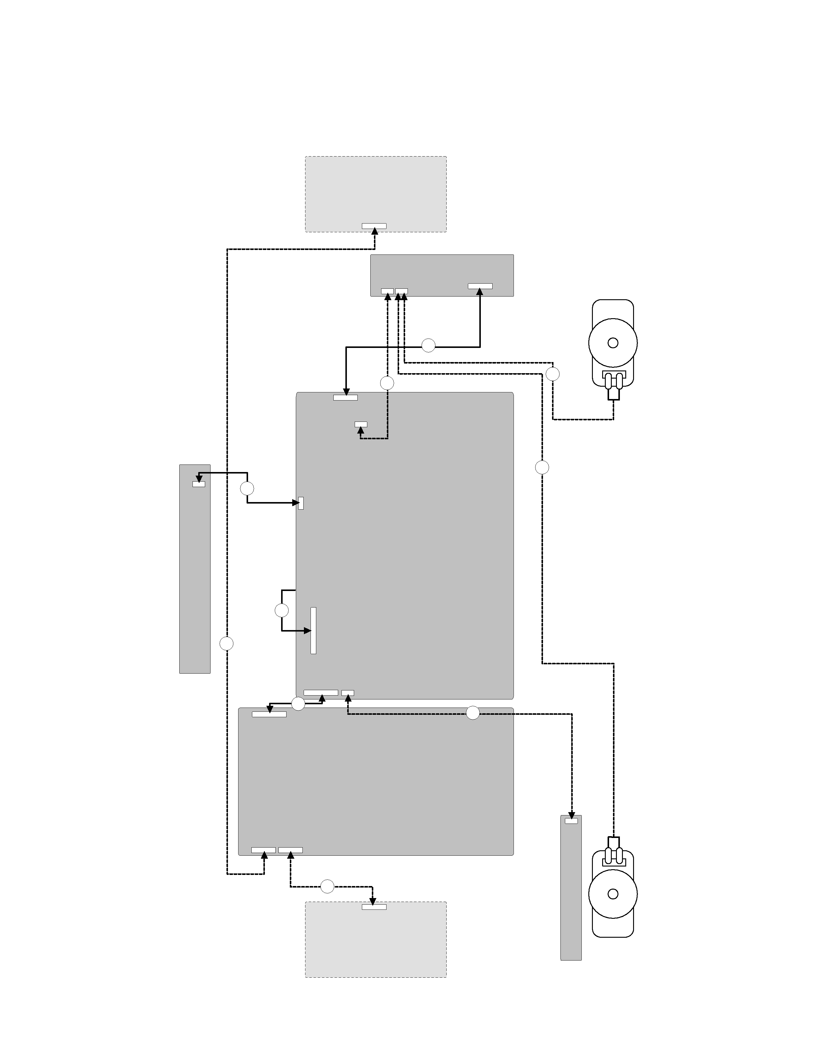
8-1. WIRING DIAGRAM
2
5
9
8
7
6
6
4
3
1
CONTR
O
L
BO
ARD
MAIN
BO
ARD
A
C
PO
WER
BO
ARD
INVER
TER
BO
ARD
- 59 -
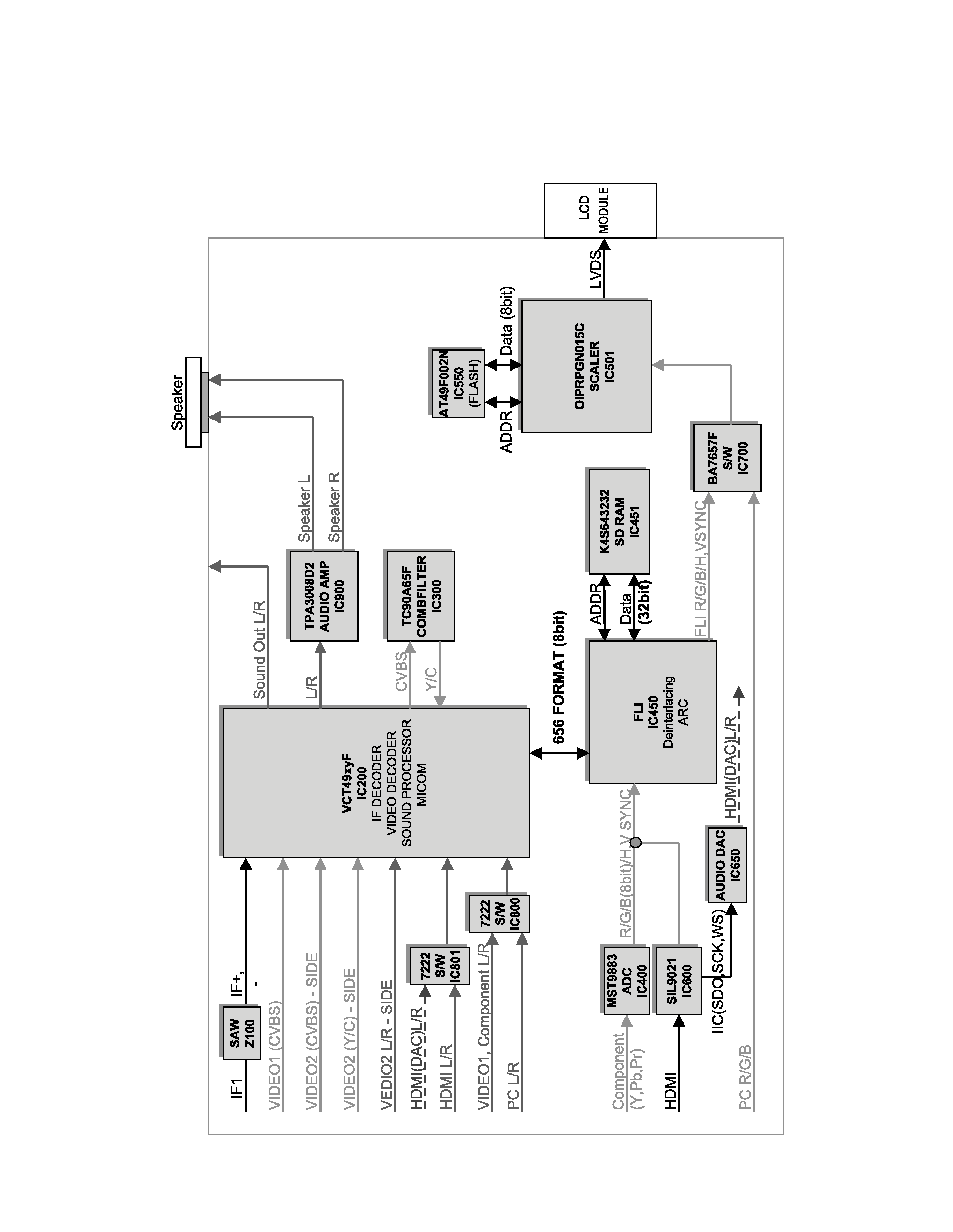
8-2. BLOCK DIAGRAM

- 60 -
1. Video Controller Unit & Display Data Conversion Unit
The video controller unit receives the video signals inputted through the tuner, AV port (VIDEO1, VIDEO2), and
converts them into an ITU656 signal through the microcomputer (VCTI) combined with the video decoder that
integrates various functions in one chip.
Either the analog RGB(FLI2300) signal or PC RGB signal is selected by the switching IC and inputted to a scaler
(GM2221), which is sent to the LCD module after being modified to an LVDS signal through the integrated LVDS IC.
VCTi is the main microprocessor that handles video signal processing and sound signal processing.
It also manages the RF signals received from the tuner.
The scaler can control timing to fit into the LCD panel, and can also control the size and position of the input
signal.
2. Power Supply Unit
The power supply unit provides 5V, 15V and 33V DC power to the Mainboard.
The 33V is directly used for the tuner.
15V power is directly used by the sound amplifier IC and is also used to generate 5V and 3.3V power through the
Step-Down DC/DC Converter. 5V power is converted to 3.3V and 1.8V power through the regulator, which in turn
supplies electrical power for ICs such as VCTI and scaler.
* The information contained in this section subjects to model.