
SERVICE MANUAL
FILE NO. 050-200414
14DL74 / 20DL74
LCD TELEVISION
DOCUMENT CREATED IN JAPAN, May, 2004

Table of Contents
2
WARNINGS ...............................................................................................................................................................3
SERVICE SAFETY PRECAUTIONS .........................................................................................................................4
Examples of Marks................................................................................................................................................. 4
HANDLING THE LCD MODULE ................................................................................................................................5
Safety Precautions................................................................................................................................................. 5
Precautions for Handling the LCD Module............................................................................................................. 5
LOCATION OF CONTROLS ......................................................................................................................................6
TV Front ................................................................................................................................................................. 6
TV Rear.................................................................................................................................................................. 6
Remote Control ..................................................................................................................................................... 7
LAYOUT OF MAJOR BOARDS ................................................................................................................................8
MECHANICAL DISASSEMBLY .................................................................................................................................9
PACKING DISASSEMBLY .......................................................................................................................................12
WIRING CONNECTION DIAGRAM .........................................................................................................................13
CIRCUIT BOARD DIAGRAMS.................................................................................................................................14
MAINBOARD ....................................................................................................................................................... 14
KEY/CONTROL BOARD...................................................................................................................................... 18
LIGHT-RECEIVING BOARD................................................................................................................................ 18
EARPHONE BOARD ........................................................................................................................................... 19
SCHEMATIC DIAGRAMS ........................................................................................................................................20
BLOCK DIAGRAM ............................................................................................................................................... 21
STANDARD MCU ................................................................................................................................................ 22
SCALER............................................................................................................................................................... 23
SCALER MEMORY.............................................................................................................................................. 24
VIDEO DECODER ............................................................................................................................................... 25
V-CHIP & CC ....................................................................................................................................................... 26
AUDIO PROCESSOR.......................................................................................................................................... 27
POWER AMPLIFIER............................................................................................................................................ 28
AV SWITCH ......................................................................................................................................................... 29
NTSC TUNER ...................................................................................................................................................... 30
USA MTS ............................................................................................................................................................. 31
PANEL CONNECTOR ......................................................................................................................................... 32
POWER SYSTEMS ............................................................................................................................................. 33
I/O CONNECTOR ................................................................................................................................................ 34
USA 480P ............................................................................................................................................................ 35
IR BOARD............................................................................................................................................................ 36
EARPHONE BOARD ........................................................................................................................................... 37
KEYPAD BOARD................................................................................................................................................. 38
CHASSIS AND CABINET REPLACEMENT PARTS LIST ......................................................................................39
14DL74 ................................................................................................................................................................ 39
20DL74 ................................................................................................................................................................ 40
SPECIFICATIONS ....................................................................................................................................................41
14/20DL74 LCD TV Specifications ...................................................................................................................... 41
3
WARNINGS
Take care to heed the following warnings:
KEEP CHILDREN
AWAY
Always advise users to keep children away.
There is danger of injury to children from tools, disassembled products, etc.
UNPLUG
Always disconnect the power plug before starting work whenever power is not
required.
Failure to disconnect the power plug before starting work can result in electrical
shock.
SHOCK HAZARD
Depending on the model, use an insulation transformer or wear gloves when
servicing with the power on, and disconnect the power plug to avoid electrical
shock when replacing parts.
In some cases, alternating current is also impressed in the chassis, so electrical
shock is possible if the chassis is contacted with the power on.
USE SPECIFIED
PARTS
Always use the replacement parts specified for the particular model when mak-
ing repairs. The parts used in products have the necessary safety characteris-
tics such as inflammability, voltage resistance, etc.; therefore, use only
replacement parts that have these same characteristics.
Use only the specified parts when the
mark is included in a circuit diagram
or parts list.
CAUTION FOR
WIRING
Parts mounting and routing of the wiring should be the same as that used origi-
nally.
For safety purposes, insulating materials such as tubing or tape is sometimes
used and printed circuit boards are sometimes mounted floating.
Also make sure that wiring is routed and clamped to avoid parts that generate
heat and which use high voltage. Always follow the original scheme.
CAUTION FOR
ASSEMBLY/WIRING
After a repair has been completed, reassemble all disassembled parts, and
route and reconnect the wiring, in accordance with the original scheme.
Do not allow internal wiring to be pinched by cabinets, panels, etc. Any error in
reassembly or wiring can result in electrical leakage, flame, etc., and may be
hazardous.
CHECK INSULA-
TION RESISTANCE
After completing the work, disconnect the power plug from the outlet, remove
the antenna, turn on the power switch. Then, use a 500V insulation resistance
meter to check the insulation resistance of the antenna terminal, other metallic
parts and between the prongs of the power plug to make sure that the insula-
tion resistance is 1M
or more. The set will require inspection and repair if the
insulation resistance is below this value.
PROHIBIT REMOD-
ELLING
Never remodel the product in any way.
Remodelling can result in improper operation, malfunction, or electrical leakage
and flame,
which may be hazardous
4
2Unplug
H
4
SERVICE SAFETY PRECAUTIONS
The caution items shown here describe major safety issues and should always be observed.
The meanings of the various indications are as follows.
* Physical damage means major damage to a home, furnishings and other possessions.
Examples of Marks
WARNING
Indicates a hypothetical situation in which service personnel and nearby third parties,
or even end users due to a product defect after the service operation is completed,
could possibly be in danger of injury or even death in the event of operational error.
CAUTION
Indicates a hypothetical situation in which service personnel and nearby third parties,
or even end users after the service operation is completed, could possibly be in dan-
ger of injury, or where there could be physical damage in the event of operational
error.
SHOCK HAZARD
The
indicates caution (including danger and warning).
The actual meaning of this caution is indicated inside the > or nearby illustra-
tions or text.
The example shown to the left indicates the danger of "electrical shock".
PROHIBIT
DISASSEMBLY
The
indicates a forbidden action.
The actual meaning of this caution is indicated inside the or nearby illustrations
or text.
The example shown to the left indicates that disassembly is forbidden.
UNPLUG
The
indicates a forced action (an action that must be performed).
The actual meaning of this forced action is indicated by
or nearby illustra-
tions or text.
The example shown to the left indicates that the power plug must be discon-
nected.
H
4
2Unplug
5
HANDLING THE LCD MODULE
Safety Precautions
In the event that the screen is damaged or the liq-
uid crystal (fluid) leaks, do not breathe in or drink
this fluid. Also, never touch this fluid.
Such actions could cause toxicity or skin irritation.
If this fluid should enter the mouth, rinse the mouth
thoroughly with water. If the fluid should contact the
skin or clothing, wipe off with alcohol, etc., and
rinse thoroughly with water. If the fluid should enter
the eyes, immediately rinse the eyes thoroughly
with running water.
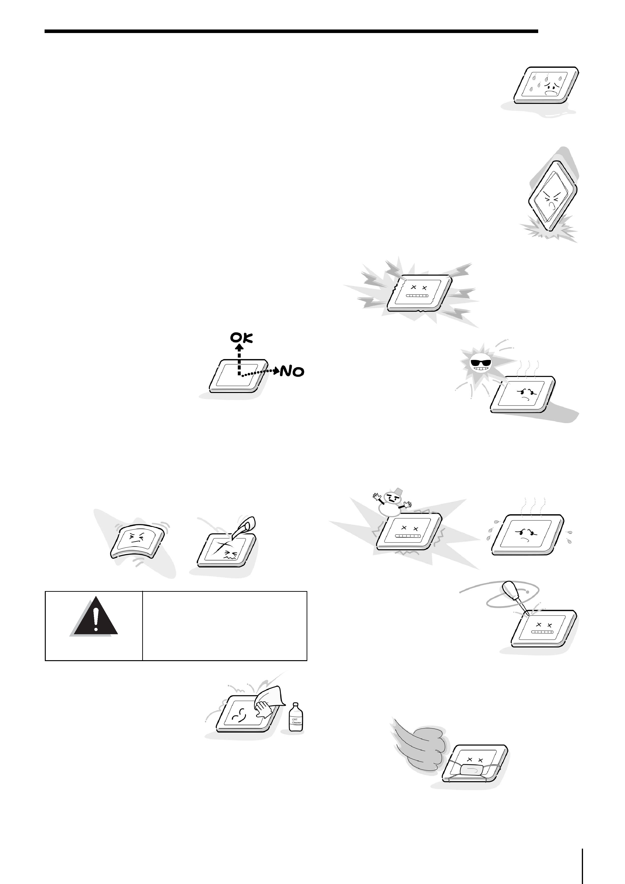
Precautions for Handling the LCD
Module
The LCD module can easily be damaged during
disassembly or reassembly; therefore, always
observe the following precautions when handling
the module.
1. When attaching the LCD
module to the LCD cover,
position it appropriately
and fasten at the position
where the display can be
viewed most conve-
niently.
2. Carefully align the holes at all four corners of the LCD
module with the corresponding holes in the LCD cover
and fasten with screws. Do not strongly push on the
module because any impact can adversely affect the
performance. Also use caution when handling the
polarized screen because it can easily be damaged.
3. If the panel surface becomes
soiled, wipe with cotton or a
soft cloth. If this does not
remove the soiling, breathe
on the surface and then wipe
again. If the panel surface is
extremely soiled, use a CRT
cleaner as a cleaner. Wipe off the panel surface by
drop the cleaner on the cloth. Do not drop the cleaner
on the panel. Pay attention not to scratch the panel sur-
face.
4. Leaving water or other fluids on
the panel screen for an extended
period of time can result in discol-
oration or stripes. Immediately
remove any type of fluid from the
screen.
5. Glass is used in the panel, so do not
drop or strike with hard objects.
Such actions can damage the panel.
6. CMOS-LSI circuitry is used in the
LCD module, so avoid damage due
to static electricity. When handling
the module, use a wrist ground or
anchor ground.
7. Do not expose the LCD
module to direct sun-
light or strong ultravio-
let rays for an extended
period of time.
8. Do not store the LCD
module below the tem-
perature conditions described in the specifications.
Failure to do so could result in freezing of the liquid
crystal due to cold air or loss of resilience or other
damage.
9. Do not disassemble the
LCD module. Such
actions could result in
improper operation.
10.When transporting the
LCD module, do not use
packing containing
epoxy resin (amine) or silicon resin (alcohol or oxim).
The gas generated by these materials can cause loss of
polarity.
CAUTION
The metal edges of the LCD
module are sharp, so use cau-
tion to avoid injury.