ORDER NO. EMID0306003C0
A4
Digital Piano
SX-PX663P / SX-PX663PC
SX-PX663EX / SX-PX663EQ / SX-PX663EG / SX-PX663EB / SX-PX663GN /
SX-PX663GM / SX-PX663GH / SX-PX663GT / SX-PX663GU
Colours
(K) ...................Black
(M) ...................Walnut (Except GH,GU)
SPECIFICATIONS
SPECIFICATIONS
1

KEYBOARD
88 KEYS
MAX. POLYPHONY
64 NOTES
SOUND
14 SOUNDS : (7 SOUNDS X 2
VARIATIONS) GRAND,
UPRIGHT, E PIANO, HARPSI,
STRINGS, ORGAN, VIBES/
VOCAL
PEDAL
SOFT, SOSTENUTO, SUSTAIN
DIGITAL EFFECT
supported
BRILLIANCE
MELLOW, BRIGHT (5 STEPS)
DIGITAL REVERB
supported (ROOM, STAGE,
HALL, CONCERT)
TOUCH SENSITIVITY
LIGHT, NORMAL, HEAVY
TRANSPOSE
G-C-F#
METRONOME
supported (TIME SIGNATURE :
OFF, 2/4, 3/4, 4/4, 5/4, 6/8)
TUNING
427.3Hz-440.0Hz-453.0Hz
SEQUENCER
TRACK (1,2), STORAGE
CAPACITY : APPROX.
4500NOTES, RECORDING
MODE : REAL TIME
DISPLAY
supported
DEMO
supported
MIDI
MULTI TIMBLE, LOCAL
CONTROL, OMNI ON,
PROGRAM CHANGE, PEDAL,
EFFECT, TRANSPOSE
MODE SET
PIANO TUNING, MINIMUM
RANGE
OTHERS
POWER SWITCH, MAIN
VOLUME, MIDI TERMINALS (IN,
OUT), PEDAL IN, AUX IN (R/
MONO, L), LINE OUT (R/ MONO,
L), HEADPHONESx2, AC IN,
INITIAL KEY
OUTPUT
80W (40W×2)
SPEAKERS
14cm×2
POWER REQUIREMENT
100W
110W (NORTH AMERICA AND
MEXICO)
AC120/ 220/ 230-240V 50/ 60Hz
AC120V 60Hz (NORTH
AMERICA AND MEXICO)
AC230-240V 50/ 60Hz
(EUROPE, AUSTRALIAAND
NEW ZEALAND)
DIMENSIONES (W×H×D)
140.4cm×102.5cm×48.1cm
(55-9/32"×40-11/32"×18-15/16")
NET WEIGHT
46kg (101.4lbs)
ACCESSORIES
AC CORD, MUSIC STAND
2003 Matsushita Electric Industrial Co., Ltd. All rights reserved.
Unauthorized copying and distribution is a violation of law.
2

1. Warning
To prevent the risk of fire, smoke, or electrical shock and to ensure safe operation, please be sure to
follow the safety guidelines below.
1. At places where special caution is required, the necessary safety
precautions are clearly labeled or printed, for example, on the cabinet,
or on the part concerned. Please follow these safety precautions, and
also those listed in the Owner'sManual.
2. Parts which have a
mark in the circuit diagram or in the parts list
are essential for safety. When replacing these parts, be sure to use
only the specified parts.
3. Use the specified types for internal wiring (double-insulated wiring,
etc.).
4. When replacing parts on the AC primary side (power transformer,
electric switch, electrical cord, noise-prevention condenser, etc.), wind
the lead wire and secure it by soldering.
5. Do not let the wiring come into contact with heat-emitting devices
(fuse resistor, radiator plate, etc.).
6. When replacing the wiring, make sure that it is not in contact with the
unfinished or rough edge of a part.
7. When replacing the power cord (except for the plug-in type), tug it
from various directions to confirm that it does not slip out of place.
8. Spacing
If soldering was done on the AC primary circuit, confirm that the
interval between the soldered terminals or between the terminal and
surrounding metallic parts is at least the minimum required (between
the primary circuit and the chassis: atleast6.5 mm; between primary
circuit terminals: at least 4.0 mm; between primary circuit terminals
and secondary circuit terminals: at least 6.5 mm.).
2. Safety Precaution
3
2.1. Safety Precaution
1. Before servicing, unplug the power cord to prevent an electric shock.
2. When replacing parts, use only the manufacturer's recommended
components for safety.
3. Check the condition of the power cord. Replace if wear or damage is
evident.
4. After servicing, be sure to restore the lead dress, insulation barriers,
insulation papers, shields, etc.
5. Before returning the serviced equipment to the customer, be sure to
make the following insulation resistance test to prevent the customer
from being exposed to a shock hazard.
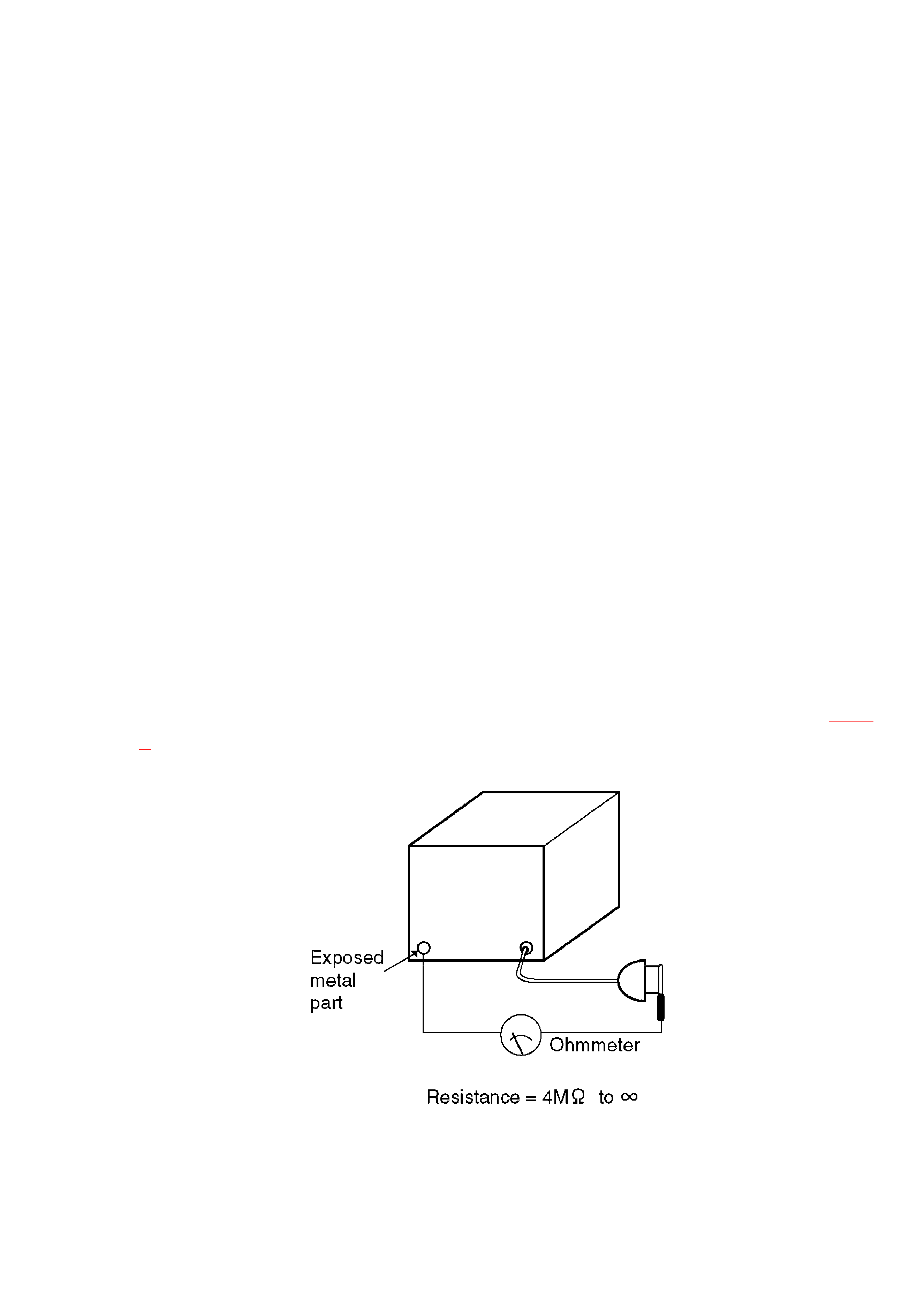
2.2. Insulation Resistance Test
1. Unplug the power cord and short the prongs of the plug with a jumper
wire.
2. Turn on the power switch.
3. Measure the resistance value with an ohmmeter between the jumpered
AC plug and each exposed metal cabinet part, such as screw heads,
connectors, control shafts, handle brackets, etc. Measurements
should range from 4 MOhm to infinity for allexposedparts. (refer to Fig.
1 )
Fig. 1
3. How to Assemble the Piano
4
4. Sounds and Effects
5. Initial Setting
The following procedure resets all programmable settings, functions and memories to their initialized
(factory-preset) status.
Use this procedure if the buttons, keys, etc. malfunction, or when you wish to reset the memories and
functions.
1. Turn off the POWER button.
2. While pressing the INITIAL key at the same time, turn the POWER
button on again.
Or, you can press the INITIAL key while the MODE SET button is pressed.
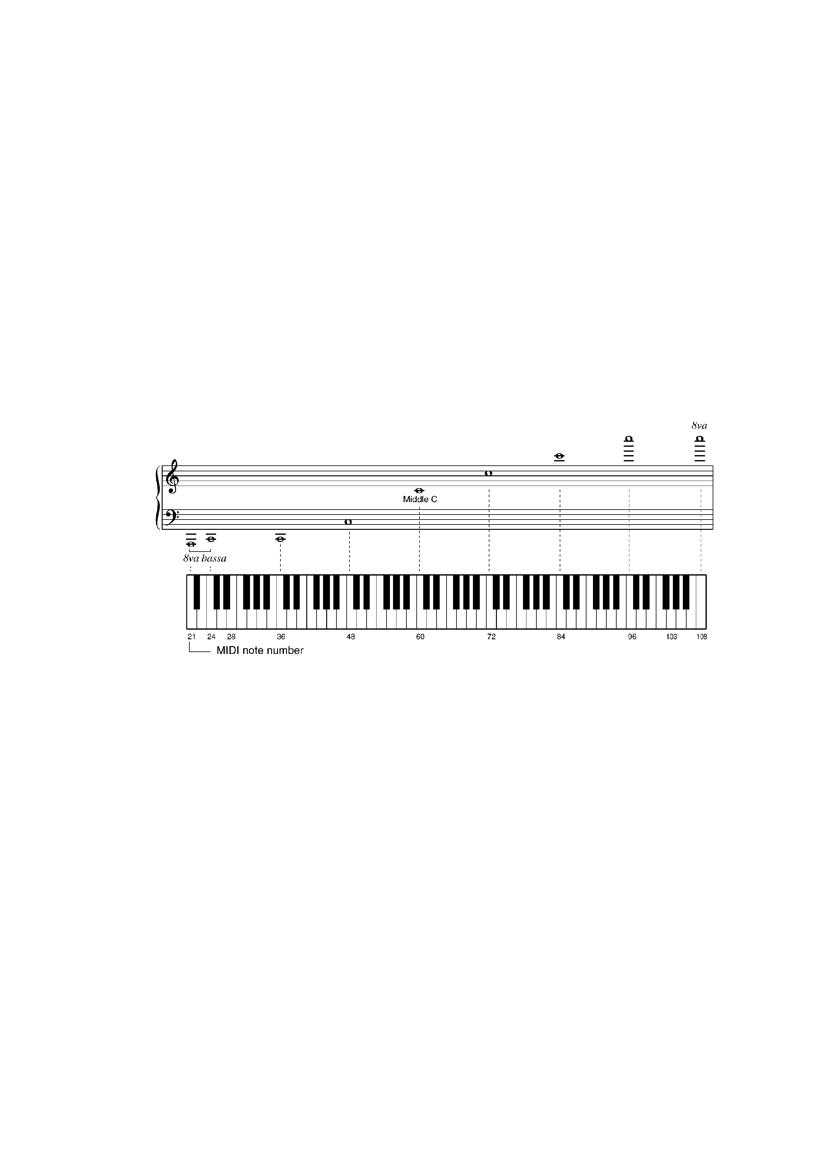
6. Keyboard Ranges and MIDI Note Number
7. Connections
8. Symptom which Apper to be Signs of Trouble
9. Parts Location
5