Order No. AD0205106S2
Stereo Integrated Amplifier
SU-V500M2 / SU-V620M2
Color
(K)...........Black Type
Areas
(E)...........Europe.
(EB).........Great Britain.
(EG).........Germany.
Addition and change of the parts for improvement in safety
Please use this supplement manual together with the service
manuals for Model No.SU-V500M2 E/EB/EG, Order No.AD0104090C2
(CDR01051AOX) and Model No.SU-V620M2 E/EB/EG, Order
No.AD9902029C2.
2002 Matsushita Electric Industrial Co., Ltd. All rights reserved.
Unauthorized copying and distribution is a violation of law.
1. Purpose
1.1. SU-V500M2
1
- Fan unit, Fan cover, and Screw are added for improvement in
safety.
- Electric circuit is changed in accordance with Fan unit addition.
1.2. SU-V620M2
- Fan cover, and Screw are added for improvement in safety.
2. About the applicable model
- The object is only the model fan cover equipped from the first. The
model fan cover isn't equipped from the first is the outside of the
object, because fan cover can't be equipped for the different form
of *1 rearpanel.
*1
Rear panel: The parts of rear panel aren't supplid.
3. Fan unit is added for improvement in safety
- The object model of this chapter is SU-V500M2.
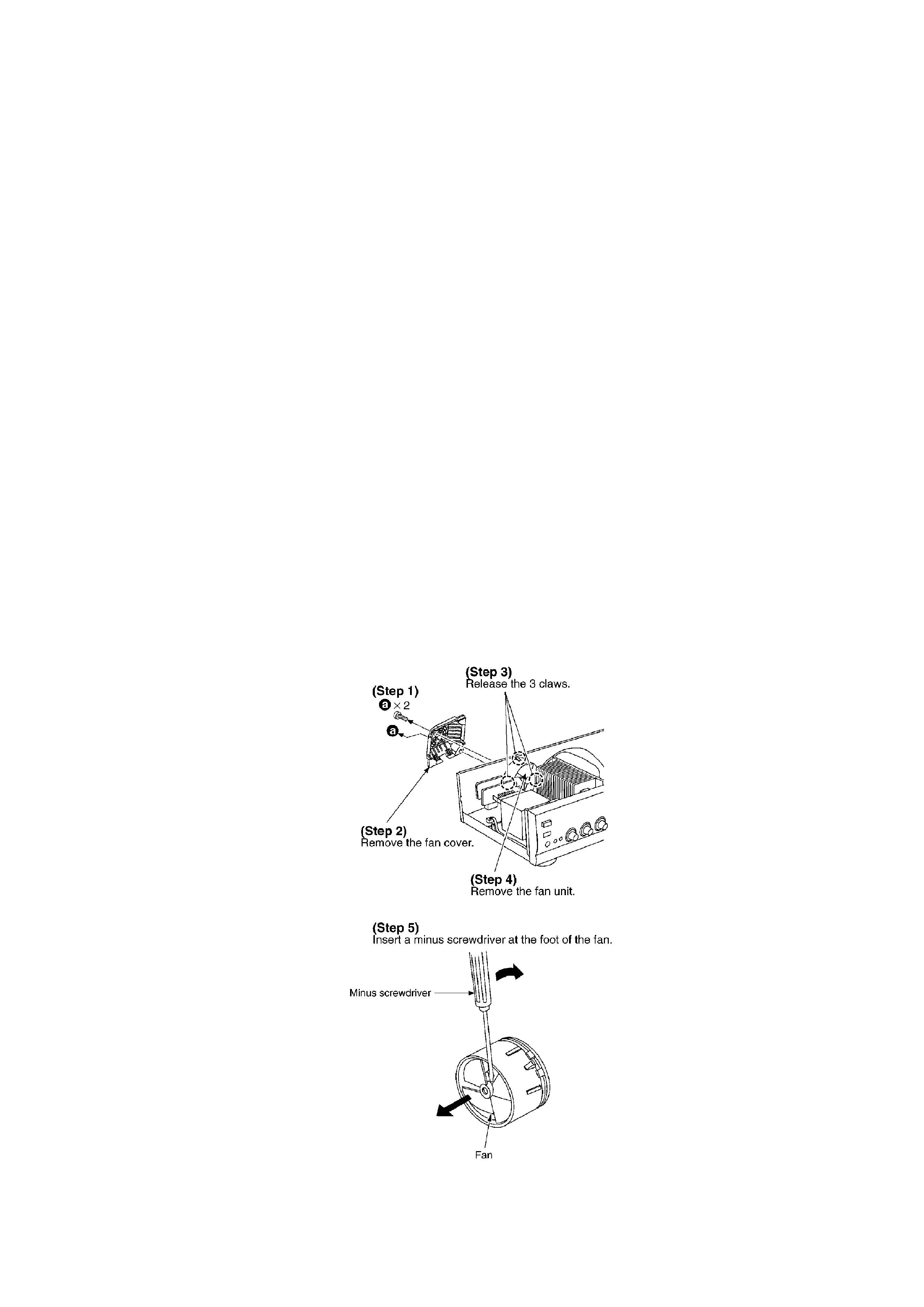
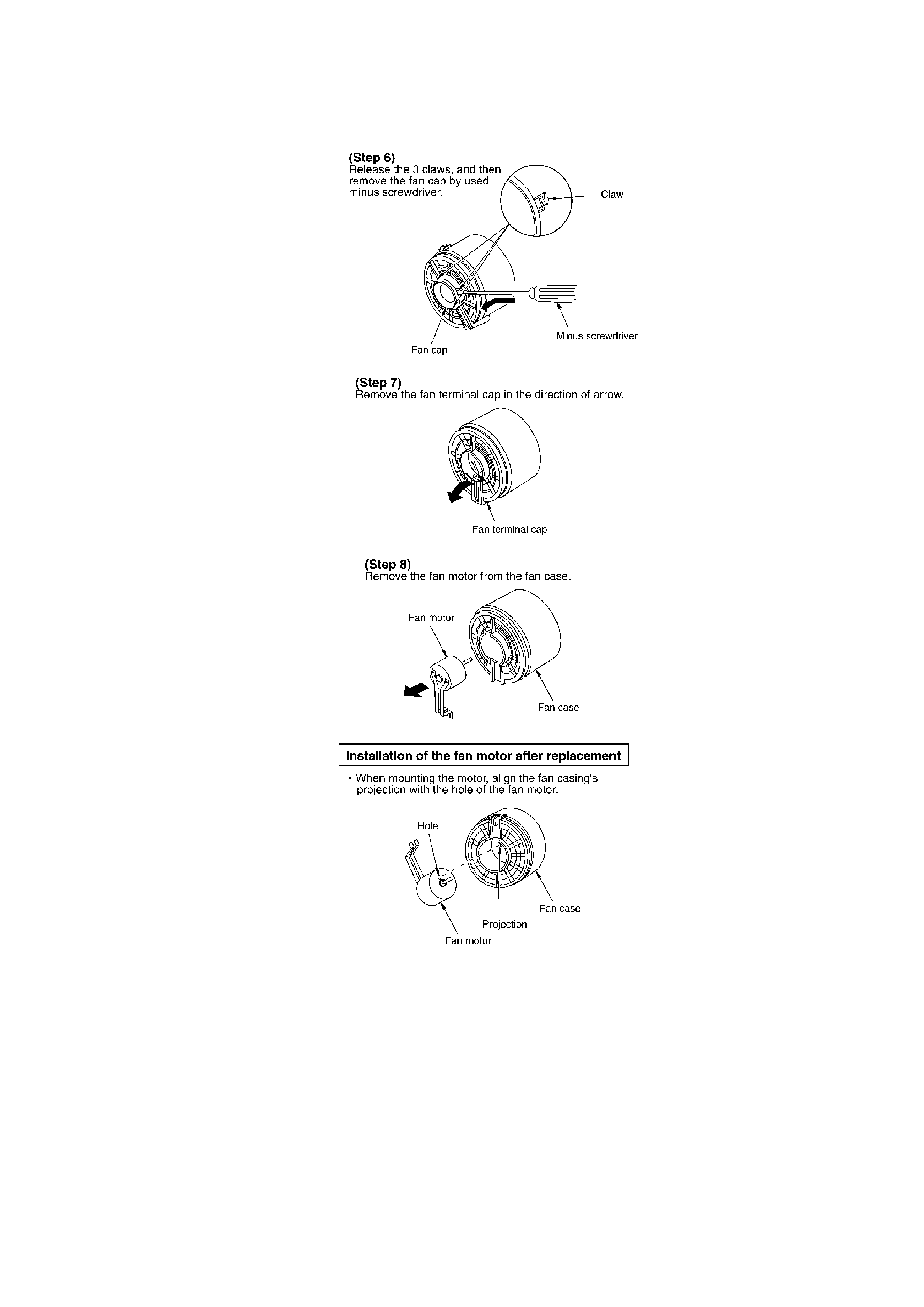
3.1. Replacement of the fan motor
Refer to <7.1.Check for the operation P.C.B. and tone amp P.C.B.> of original service manual SU-
V500M2 E/EB/EG, Order No.AD 0104090C2 for removal of a cabinet.
- Follow the (Step 1) - (Step 3) of item 7.1.
2
3.2. Schematic Diagram Notes
- This schematic diagram may be modified at any time with the
development of new technology.
Notes:
S401:
Tone control switch (TONE)
3
S801:
Input selector switch (PHONO)
S802:
Input selector switch (TUNER)
S803:
Input selector switch (CD)
S804:
Input selector switch (AUX)
S805:
Input selector switch (TAPE2)
S806:
Tape1 monitor switch / (TAPE1 MONITOR)
S807:
Unit on/off switch (
)
S808:
Speaker select switch / (SPEAKERS A)
S809:
Speaker select switch / (SPEAKERS B)
VR471:
Bass control VR (BASS)
VR472:
Treble control VR (TREBLE)
VR501:
Volume control VR (VOLUME)
VR502:
Balance control VR (BALANCE)
- Indicated voltage values are the standard values for the unit
measured by the DC electronic circuit tester (high-impedance)
with the chassis taken as standard. Therefore, there may exist
some errors in the voltage values, depending on
theinternalimpedance of the DC circuit tester.
No mark
4
: Power ON
- Important safety notice:
Components identified by
mark have special characteristics
important for safety.
Furthermore, special parts which have purposes of fire-retardant
(resistors), high-quality sound (capacitors), low-noise (resistors),
etc. are used.
When replacing any of components, be sure to use only
manufacturer´s specified parts shown in the parts list.
- The supply part number is described alone in the replacement
parts list.
- Caution!
IC and LSI are sensitive to static electricity.
Secondary trouble can be prevented by taking care during repair.
Cover the parts boxes made of plastics with aluminum foil.
Ground the soldering iron.
Put a conductive mat on the work table.
Do not touch the legs of IC or LSI with the fingers directly.
- Voltage and signal line
: Positive voltage line
: Negative voltage line
: Phono signal line
5