AD0104089C2
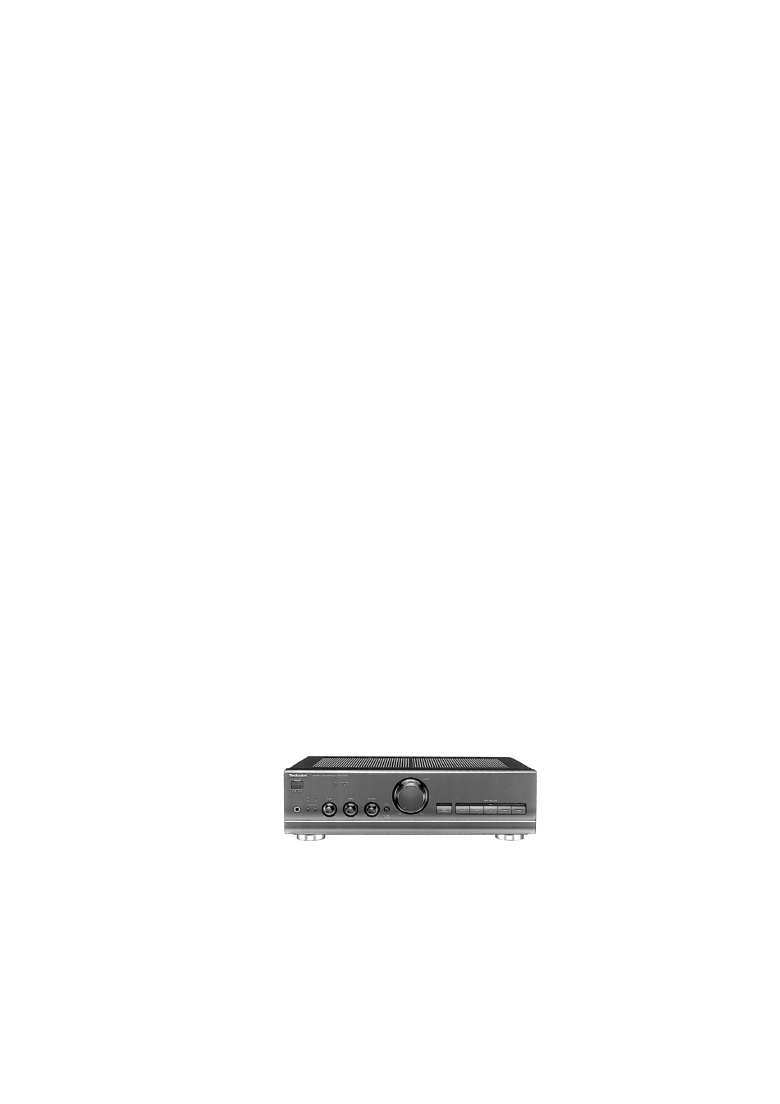
Stereo Integrated Amplifier
SU-V300M2
Colour
(K)...........Black Type
Areas
(E)...........Europe.
(EB).........Great Britain.
(EG).........Germany.
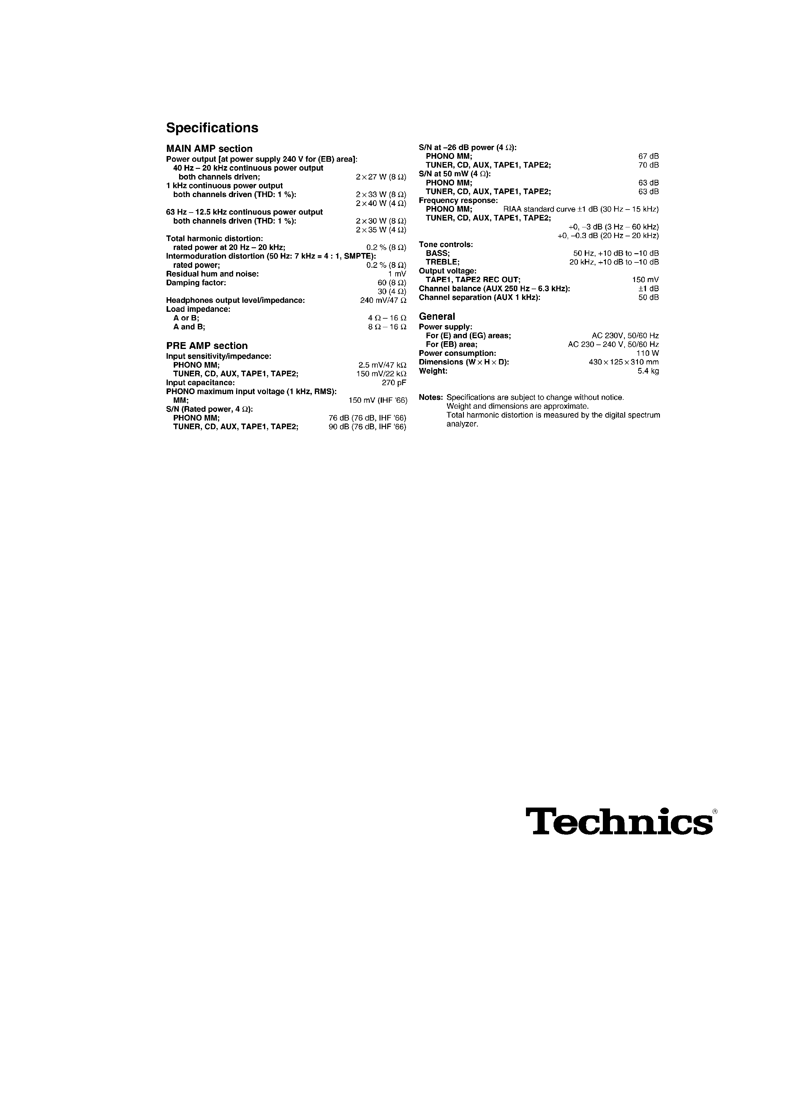
SPECIFICATIONS
1
1. Note
- The contents changed from Model No. SU-V300M2 (Order No.
AD99003072C2)
This model [SU-V300M2 (Order No. AD0104089C2)] is changed
from Model No. SU-V300M2 (Order No. AD9903072C2) about
Printed Circuit Board. So you need to use the service manual
2
properly with distinguishing the unit is sold on and after April
2001 ornot.
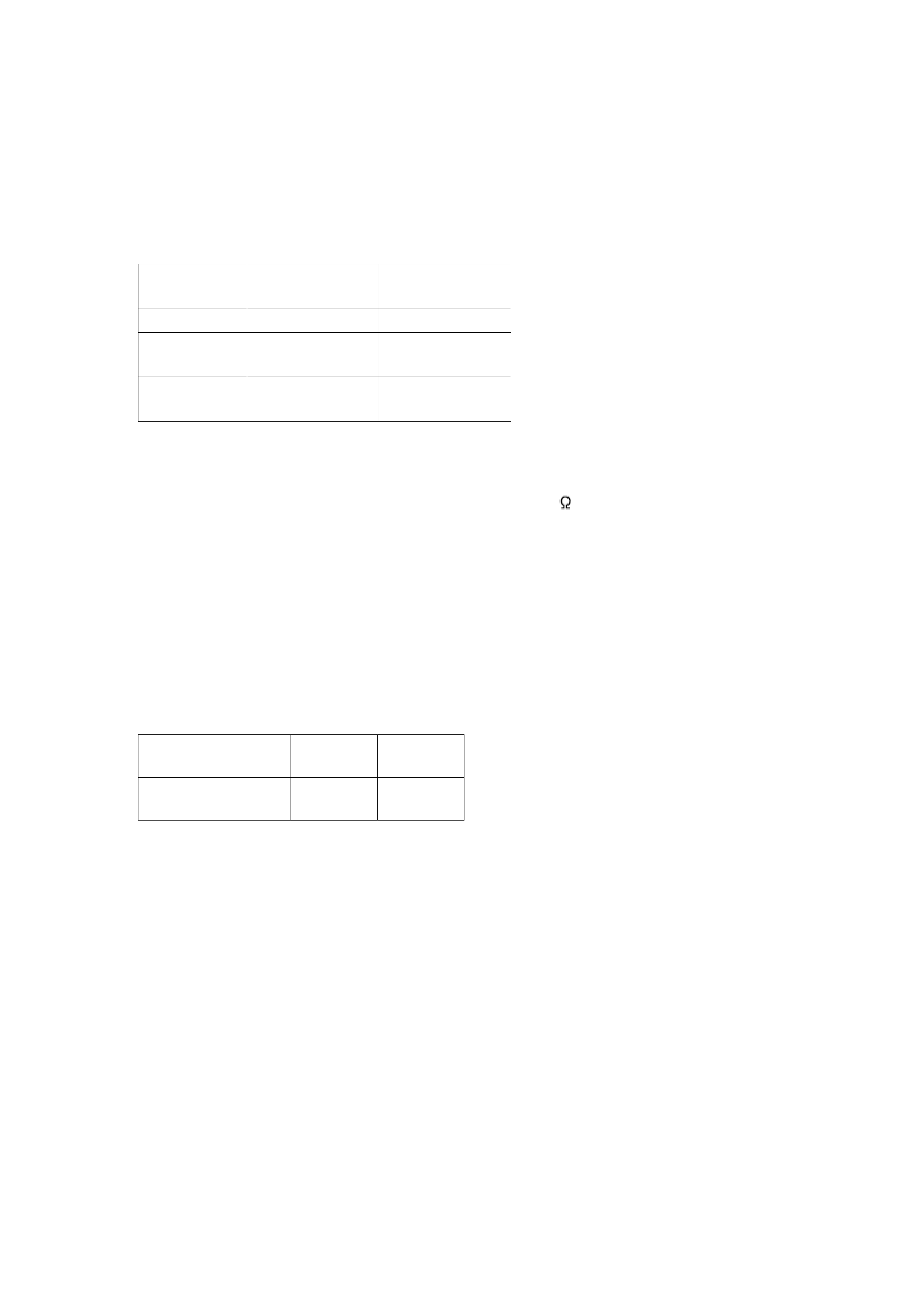
When the unit is repaired, refer to the table as shown below and
confirm IC601 and Part No. of operation P.C.B.
SU-V300M2 /
(AD903072C2)
SU-V300M2 /
(AD0104089C2)
IC601
RSN3502A
RSN3502C
Operation
P.C.B.
RJB1273BB-2
RJB1273BB-3
The time of
sales
Before April 2001 On and after
April 2001
2. Before Repairs
1. Turn off the power supply. Using a 10
, 10 W resistor, connect
both ends of power supply capacitors (C703, C704) in order to
discharge the voltage.
2. Before turning the power supply on, after completion of repair,
slowly apply the primary voltage by using a power supply voltage
controller to make sure that the consumed current at 50 Hz in NO
SIGNAL mode should be shown below with respectto supply
voltage 230/240 V.
Power supply
voltage
AC 230 V
AC 240 V
Consumed current
50 Hz
47 ~ 157
mA
45 ~ 150
mA
3. Protection Circuitry
The protection circuitry may have operated if either of the following conditions is noticed:
- No sound is heard when the power is switched ON.
- Sound stops during a performance.
The functions of this circuitry is to prevent circuitry damage if, for example, the positive and
negative speaker connection wires are shorted, or if speaker systems with an impedance less
than the indicated rated impedance of this unit are used.
If this occurs, follow the procedures outlined below.
1. Switch OFF the power.
2. Determine the cause of the problem and correct it.
3. Switch ON the power once again.
3
Note:
When the protection circuitry functions, the unit will not operate
unless the power is first switched OFF and then ON again.
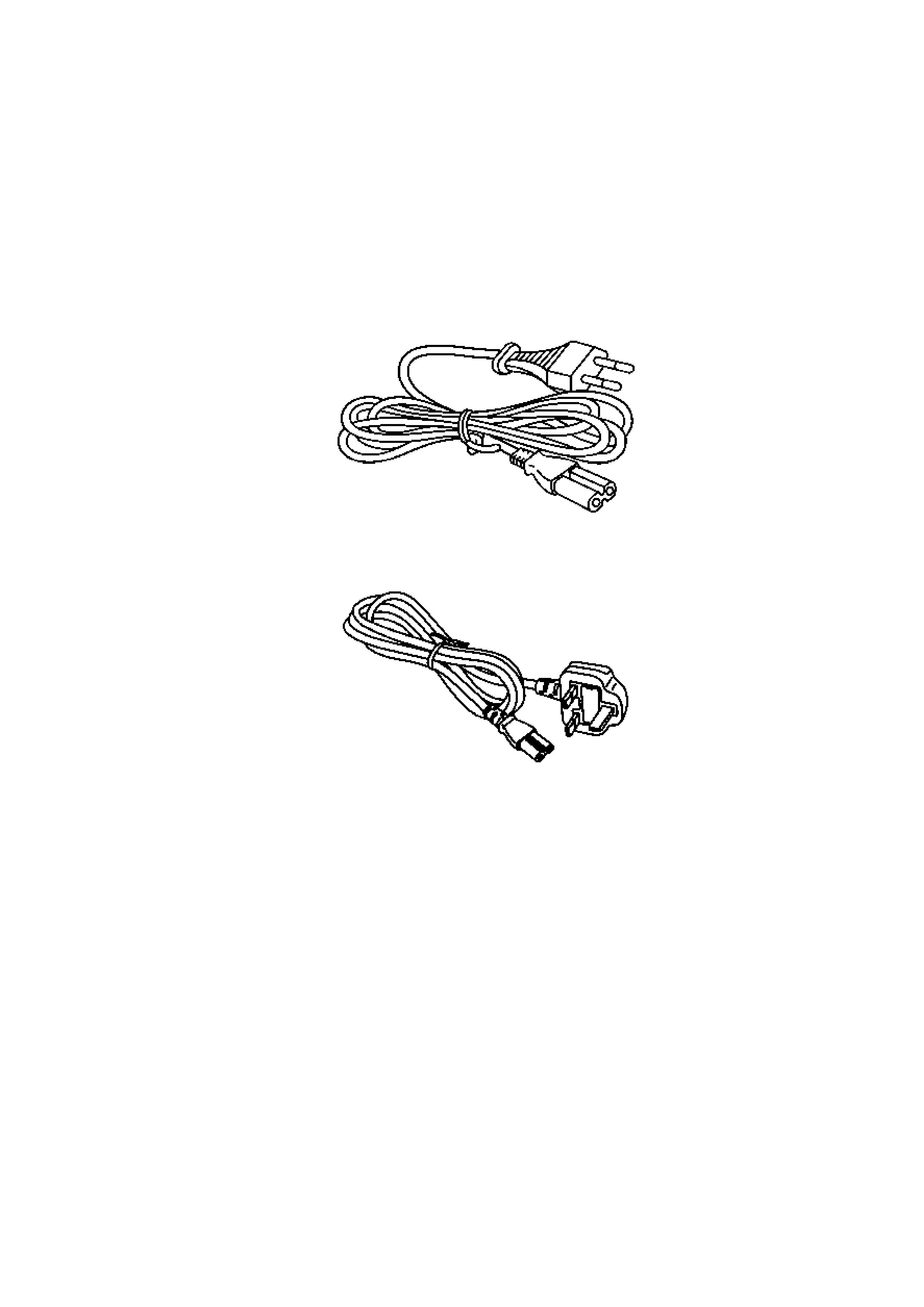
4. Accessories
- AC power supply cord for (E) and (EG) areas
(RJA0019-1X)................................1 pc.
- AC power supply cord for (EB) area
(RJA0035-2X)................................1 pc.
5. Caution for AC Mains Lead
4
6. Location of Controls
7. Operation Checks and Component Replacement /
Procedures
- This section describes procedures for checking the operation of
the major printed circuit boards and replacing the main
components.
- For reassembly after operation checks or replacement, reverse the
respective procedures. Special reassembly procedures are
5