AD9908183C1
A2
Stereo Control Amplifier
SU-C1010
Colour
(N)..........Gold Type
Area
(PP)..........U.S.A. and Canada.
SPECIFICATIONS
1999 Matsushita Electronic Industrial Co.,Ltd. All rights reserved.
Unauthorized copying and distribution is a violation of law.
1

1. Safty Precaution
This Safty Precaution is applied only in U.S.A..
1. Before servicing, unplug the power cord to prevent an electric shock.
2. When replacing parts, use only manufacture´s recommended
components for safty.
3. Check the condition of the power cord. Replace if wear or damage is
evident.
4. After servicing, be sure to restore the lead dress, insulation barriers,
insulation papers, shields, etc.
5. Before returning the serviced equipment to the customer, be sure to
make the following insulation resistance test to prevent the customer
from being exposed to a shock hazard.
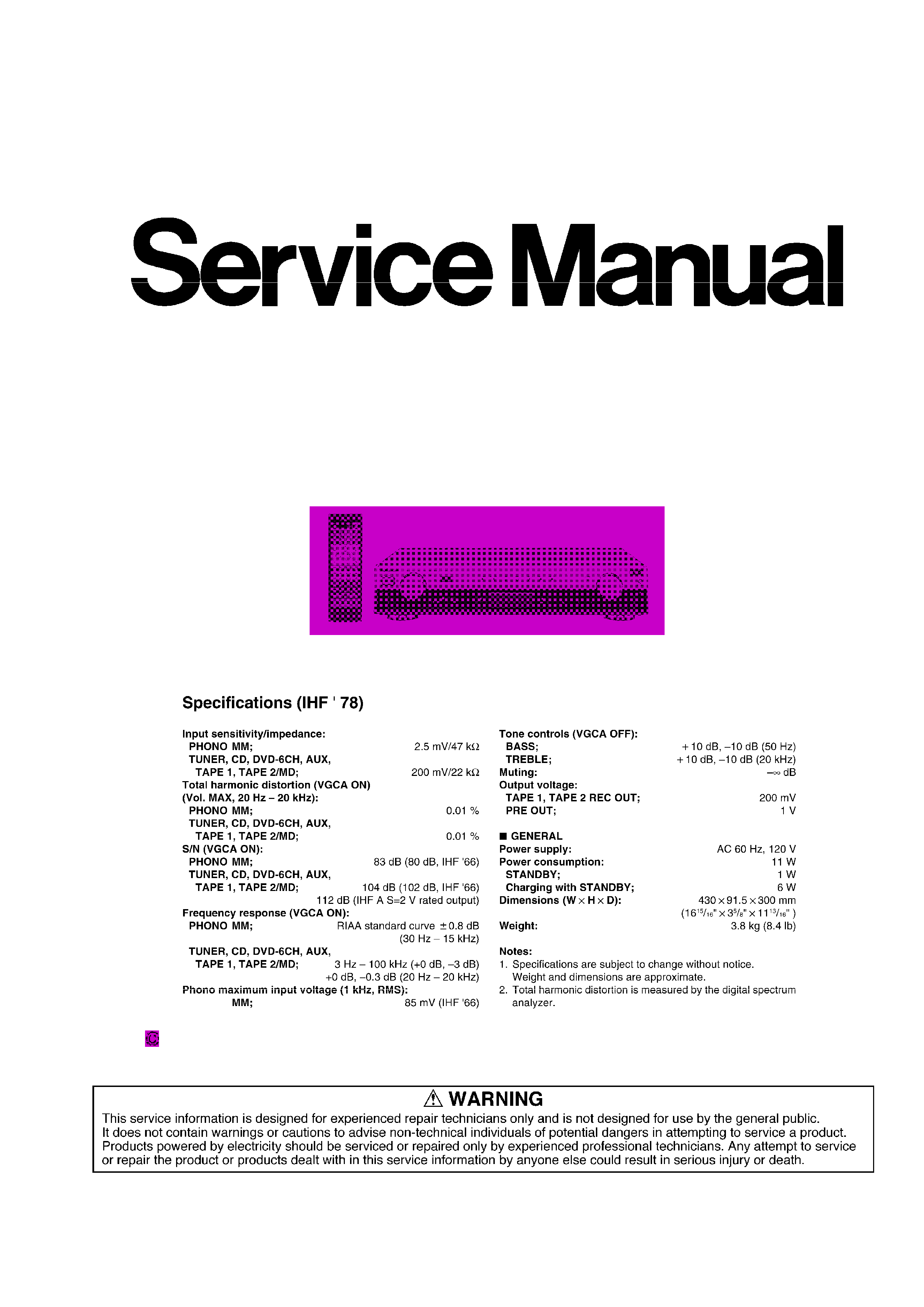
1.1. INSULATION RESISTANCE TEST
1. Unplug the power cord and short the two prongs of the plug with a
jumper wire.
2. Turn on the power switch.
3. Mesure the resistance value with ohmmeter between the jumpered AC
plug and each exposed metal cabinet parts, such as screwheads
antenna, control shafts, handle brackets, etc. Equipment with antenna
terminals should read between 3M
and 5.2M
to all exposed parts. /
Fig. A. / Equipment without antenna terminals should read
approximately infinity to all exposed parts. Fig. B.
Note: Some exposed parts may be isolated from the chassis by
design. These will read infinity.
4. If the measurement is outside the specified limits, there is a possibility
of a shock hazard. / The equipment should be repaired and rechecked
before it is returned to the customer.
Fig. A.
2
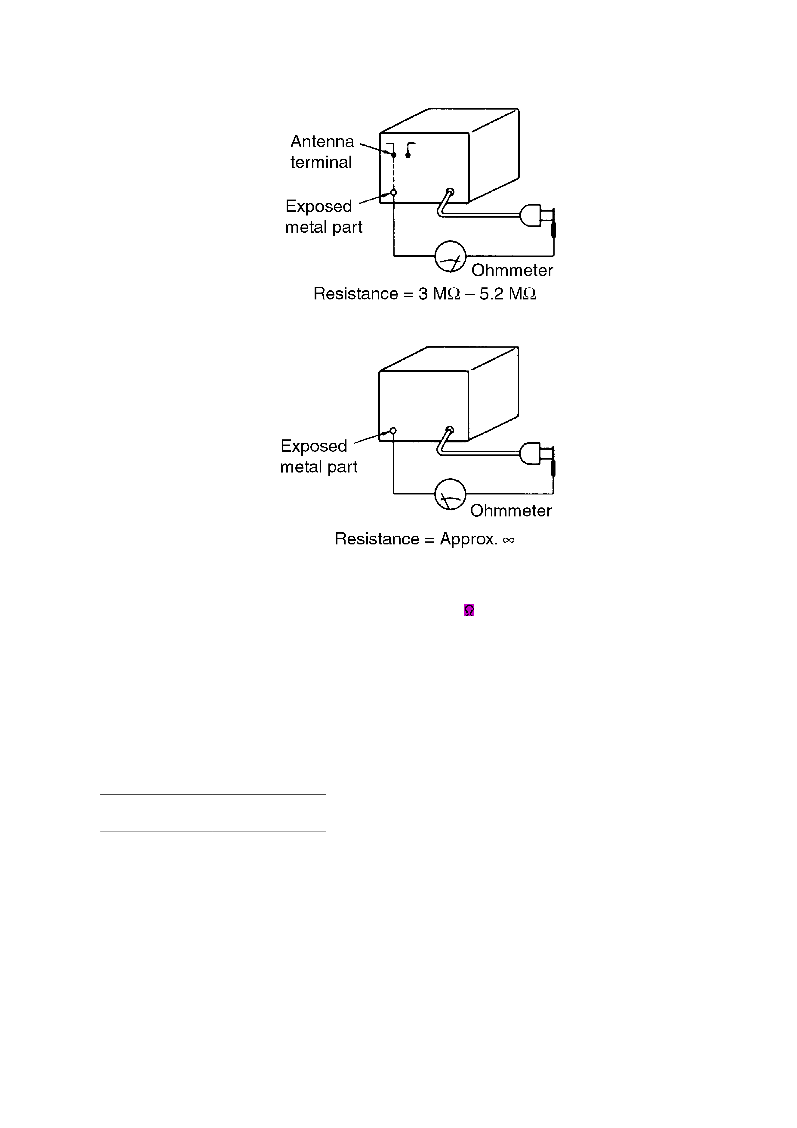
Fig. B.
2. Before Repair
1. Turn off the power supply. Using a 10
, 10 W resistor, connect both
ends of power supply capacitors (C651) in order to discharge the
voltage.
2. Before turning the power supply on, after completion of repair, slowly
apply the primary voltage by using a power supply voltage controller
to make sure that the consumed current at 60 Hz in NO SIGNAL mode
should be shown below with respect to supply voltage 120 V.
Power supply
voltage
AC 120 V, 60 Hz
Consumed
current
38-62 mA
3. Protection Circuitry
The protection circuitry may have operated if either of the following conditions is noticed:
- No sound is heard when the power is switched ON.
- Sound stops during a performance.
The functions of this circuitry is to prevent circuitry damage if, for example, the positive and negative
speaker connection wires are shorted, or if speaker systems with an impedance less than the
3
indicated rated impedance of this unit are used.
If this occurs, follow the procedure outlined bellow:
1. Switch OFF the power.
2. Determine the cause of the problem and correct it.
3. Switch ON the power once again.
Note:
When the protection circuitry functions, the unit will not operate unless
the power is first switched OFF and ON again.
4. Accessories
- AC power supply cord
(RJA0065-A)...................................1 pc.
- Remote control transmitter
(RAK-SUA11WH)............................1 pc.
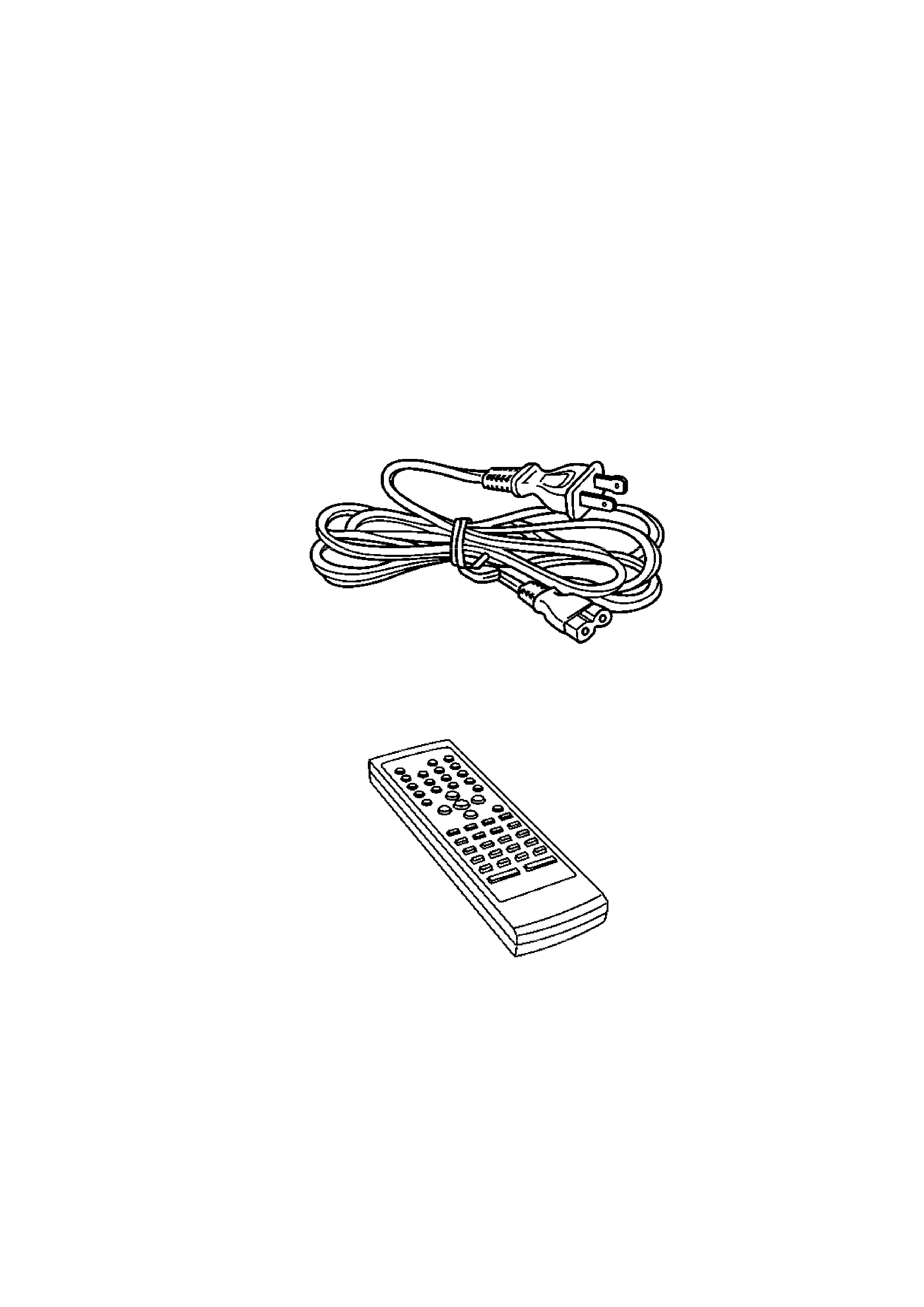
- Stereo connection cable
(SJP2276)........................................1 pc.
4
- Rechargeable battery
(P-06RM/8A14)................................1 pc.
- Batteries for remote control transmitter
(R6/LR6, AA, UM-3).......................2 pcs.
Note: These are available on sales route.
5. Operations
6. Operation Checks and Component Replacement
Procedures
5