
ORDER No. AD9912266S0
A6
Amplifier
SE-HD505 / SE-HD505MD
Areas
PP...................U.S.A. and Canada.
E.....................Europe.
EB...................Great Britain.
EG...................Germany and Italy, etc.
EP...................East Europe.
GH.................. Hong Kong.
Change of Capacitor(C303)
Please file and use this supplement manual together with the service
manual for / Model No. SE-HD505-PP,E,EB,EG,EP, Order No.
AD9904110C5. / Model No. SE-HD505-GH, Order No. AD9909215A3. /
Model No. SE-HD505MD-EG,EB, Order No. AD9904116A2.
1999 Matsushita Electric Industrial Co., Ltd. All rights reserved.
Unauthorized copying and distribution is a violation of law.
1

1. Purpose
This supplement is intended to provide the following information to the / Service Manual above:
- Replacement Parts List
2. Replacement Parts List
Ref. No.
Change of Part No.
Part Name & Description
Pcs
Remarks
ORIGINAL
NEW
C303
ECEA1AKS221
ECA1AM221B
CAPACITOR 10V 220
F
1
CHANGE
Printed in Japan P991205750 SF/TF 99JZ6T001/991104
2
ORDER NO.AD9904109C5
A6
Tuner
ST-HD505
Colour
(S) ...................Silver Type
Areas
PP....................U.S.A. and Canada.
E .....................Europe.
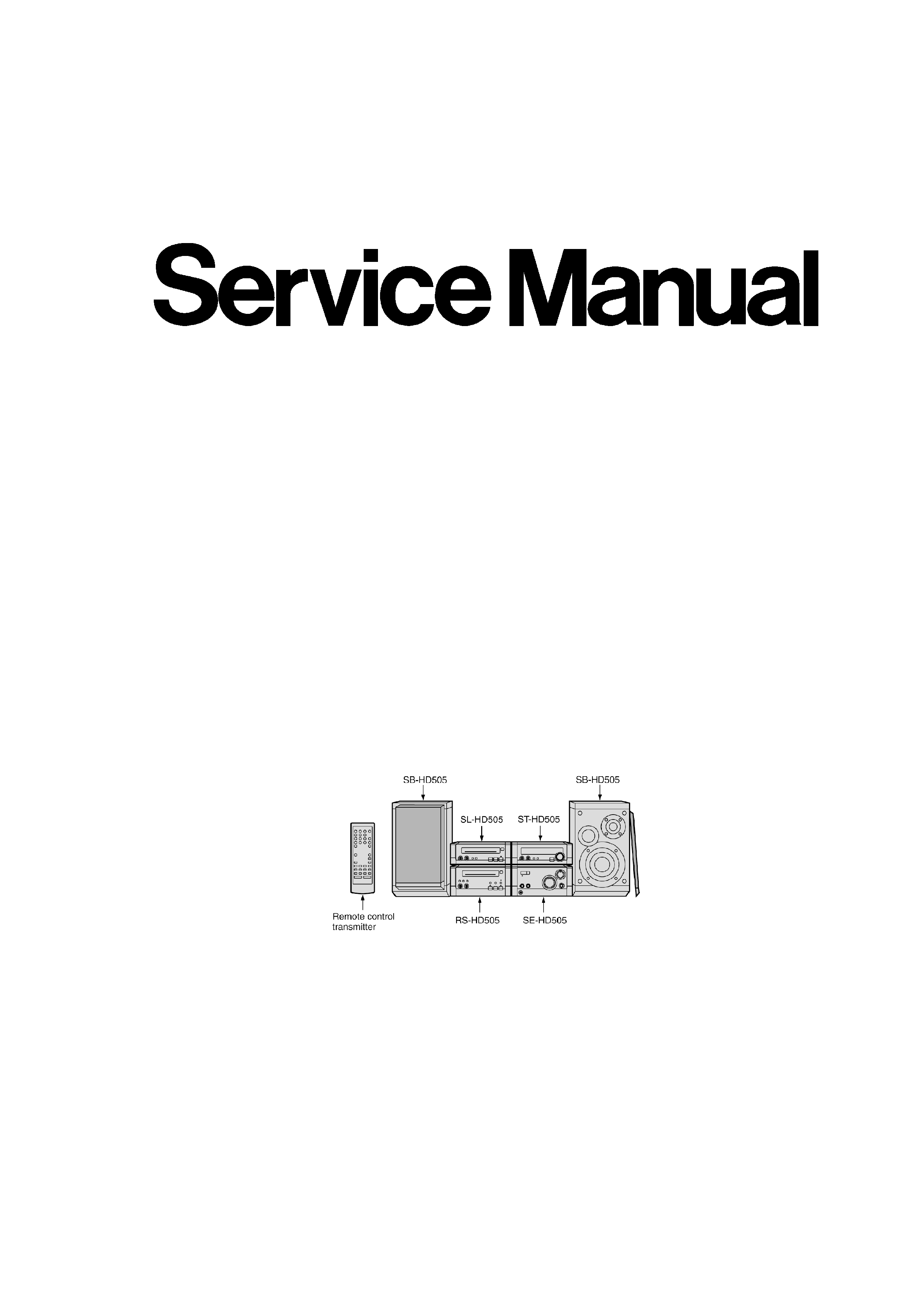
System: SC-HD505
Because of unique interconnecting cables,when a
component requires servise,send or bring in the entire
system.
Note:Refer to the service manual for Model No.SE-HD
505(ORDER NO.AD9904110C5) for information on
"ACCESSORIES", "INSTALLATION", "CONNECTIONS"
and "PACKAGING".
SPECIFICATIONS
Specification
1

Pre-amplifier section
Input sensitivity/impedance
EXTERNAL:
300mV/15k
Output level
EXTERNAL:
250mV/1.5k
FM tuner section
Frequency range(PP):
87.5-108.0MHz(0.1MHz step)
87.9-107.9MHz(0.2MHz step)
Frequency range(E):
87.50-108.00MHz(0.05MHz step)
Antenna terminals:
75
(unbalance)
AM tuner section
Frequency range(PP):
520-1710kHz(10kHz step)
Frequency range(E):
522-1629kHz(9kHz step)
520-1630kHz(10kHz step)
Timer section
Clock:
Quartz-lock type
Function:
Play timer:1 time or everyday
Rec.timer:1 time or everyday
Sleep timer:120min.intervals
General
Dimensions(WxHxD):
202x76x262.5mm
Weight:
1.2kg
Power Supply
[For (E) area only]:
AC4.2V,DC±13V/+16V/+10V/+5.6V/-24V
Power Consumption
[For (E) area only]:
15W
Notes:
1.Design and specifications are subject to change without
notice.
2.Dimensions and weight are approximate.
System/SC-HD505:
Tuner:ST-HD505,Compact Disc Player:SL-HD505,Amplifier:SE-
HD505,Cassette Deck:RS-HD505,Speakers:SB-HD505(Made in
MAES)
1999 Matsushita Electric Industrial Co., Ltd. / / All rights
reserved. Unauthorized copying and / / distribution is a violation
of law.
2

1. Before Repair
This equipment (ST-HD505), which is a component of the system, is supplied with power from
the amplifier (SE-HD505).When repairing this equipment or checking operation of the system, be
sure to connect the amplifier with it.
Power supply and operation check in the state of it as a single equipmenet are impracticable.
2. Blue LED
- The LED mounted to each side of the front panel of this set is very
sensitive to static electricity.When handling the LED base plate, be
very careful about it.
- Do not replace a blue LED singly. If replaced singly, it may be
subject to electrostatic breakdown or deterioration in quality.
When replacing the LED base plate, be sure to replace L and R
sides simultaneously to permit the brightness adjustment.
*For configuration at the time of supply of replacement parts, refer to "Printed Circuit Board
Diagram".
3. Operating Instructions
4. About the Self-Diagnostic Mode
This unit is epuipped with a self-diagnostic function which, in the event of a malfunction,
automatically displays a code indicating the nature of the malfunctions.Use this self-diagnostic
function when servicing the unit.
5. Power Source ON/OFF and Signal Check
To operate this unit ST-HD505 normally, it is necessary for connecting to the unit SE-HD505.
When operating the unit ST-HD505, be sure to connect the unit SE-HD505 by connection cable.
1. Short the section between TP302 (A.GND) and TP304(D.GND), and
as well as the section between TP303(CT) and TP304(D.GND).(As
shown in Fig.1.)
2. Connect with the Amplifier (SE-HD505).(As shown in Fig.1.)
3. Connect the AC mains lead to Amplifier (SE-HD505).(As shown in
Fig.1.)
4. Connect the speakers to speaker input terminal.(As shown in Fig.1
.)
5. Turn on the power of the Amplifier (SE-HD505).
6. Press INPUT SELECTOR to select the external souce (EXT) of the
Amplifier (SE-HD505).
3