AD0101016C2
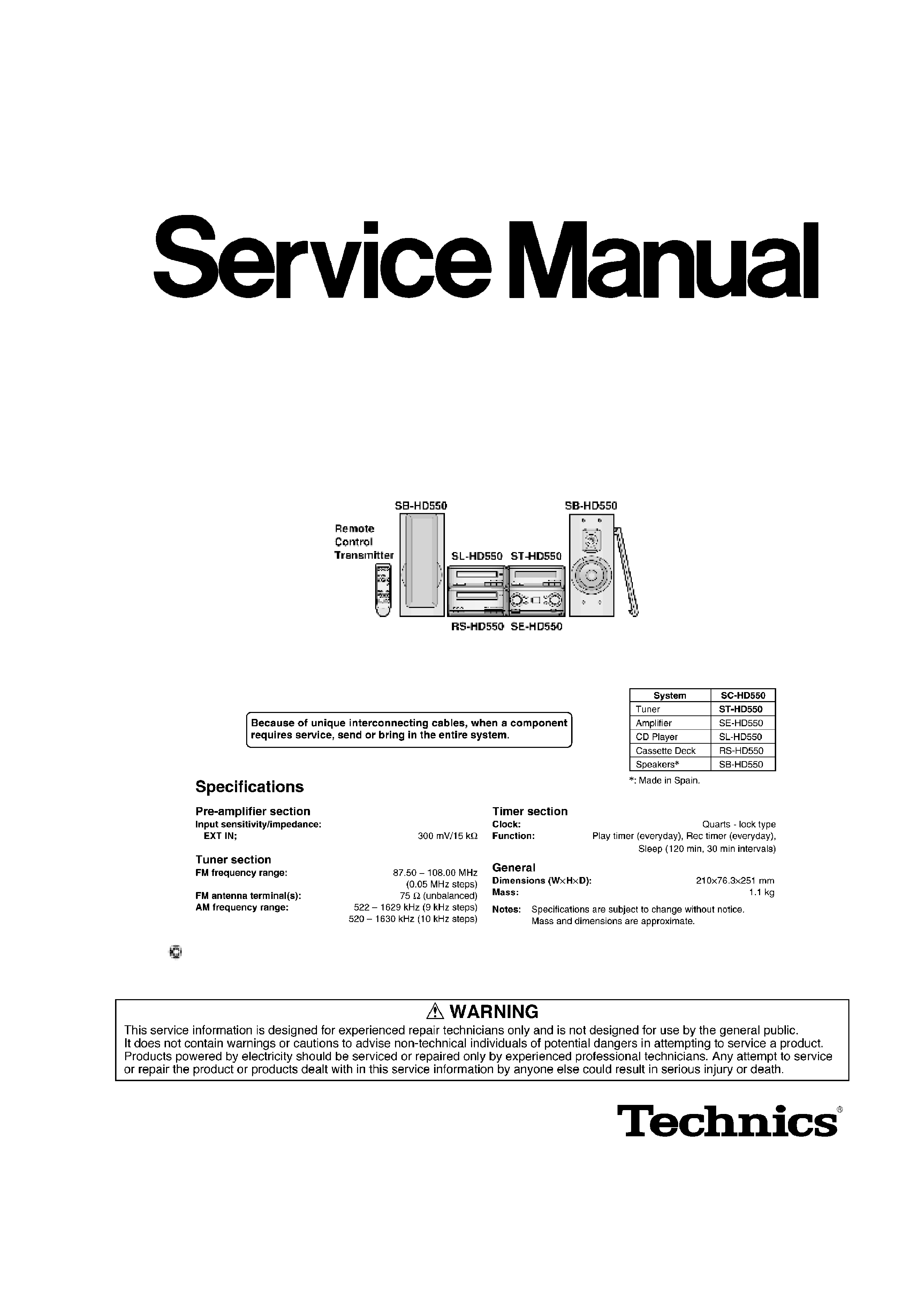
Tuner
ST-HD550
Colour
(N)...........Gold Type
Area
(E)...........Europe.
SPECIFICATIONS
2001 Matsushita Electric Industrial Co., Ltd. All rights reserved.
Unauthorized copying and distribution is a violation of law.
1
1. Note
Refer to the service manual for Model No. SE-HD550 (Order No. AD0101015C2) for information
on Accessories and Packaging.
2. Before Repair
This equipment (ST-HD550), which is a component of the system, is supplied with power from
the Amplifier (SE-HD550). When repairing this equipment or checking operation of the system,
be sure to connect to the amplifier with it.
Power supply and operation check in the state of it as a single equipment is impracticable.
3. Location of Controls
4. Operation Checks and Component Replacement /
Procedures
- This section describes procedures for checking the operation of
the major printed circuit boards and replacing the main
components.
- For reassembly after operation checks or replacement, reverse the
respective procedures. Special reassembly procedures are
described only when required.
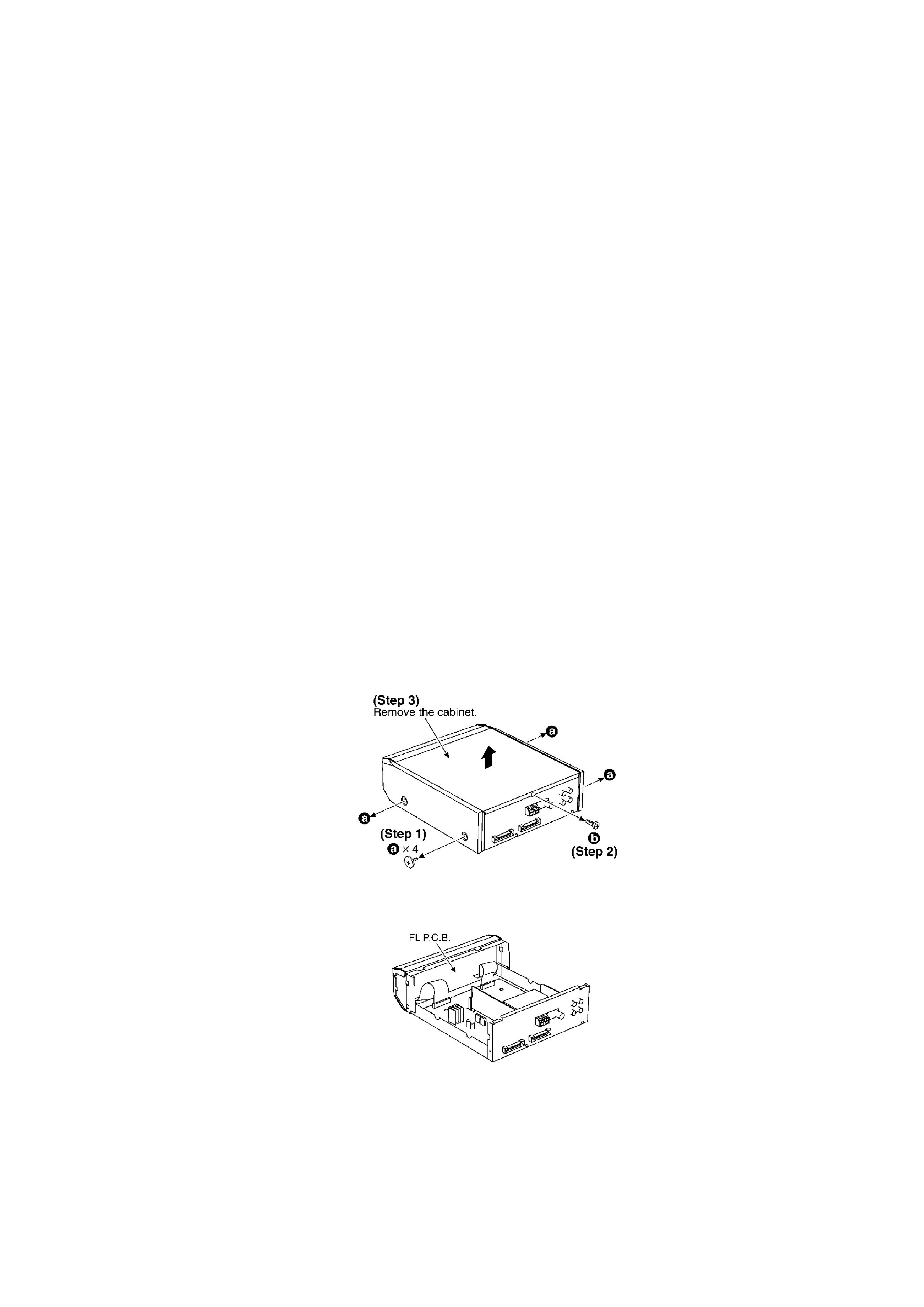
4.1. Checking for the FL P.C.B.
- Check the FL P.C.B. as shown below.
4.2. Checking for the main P.C.B.
- Follow the (Step 1) - (Step 3) of item 4.1.
2
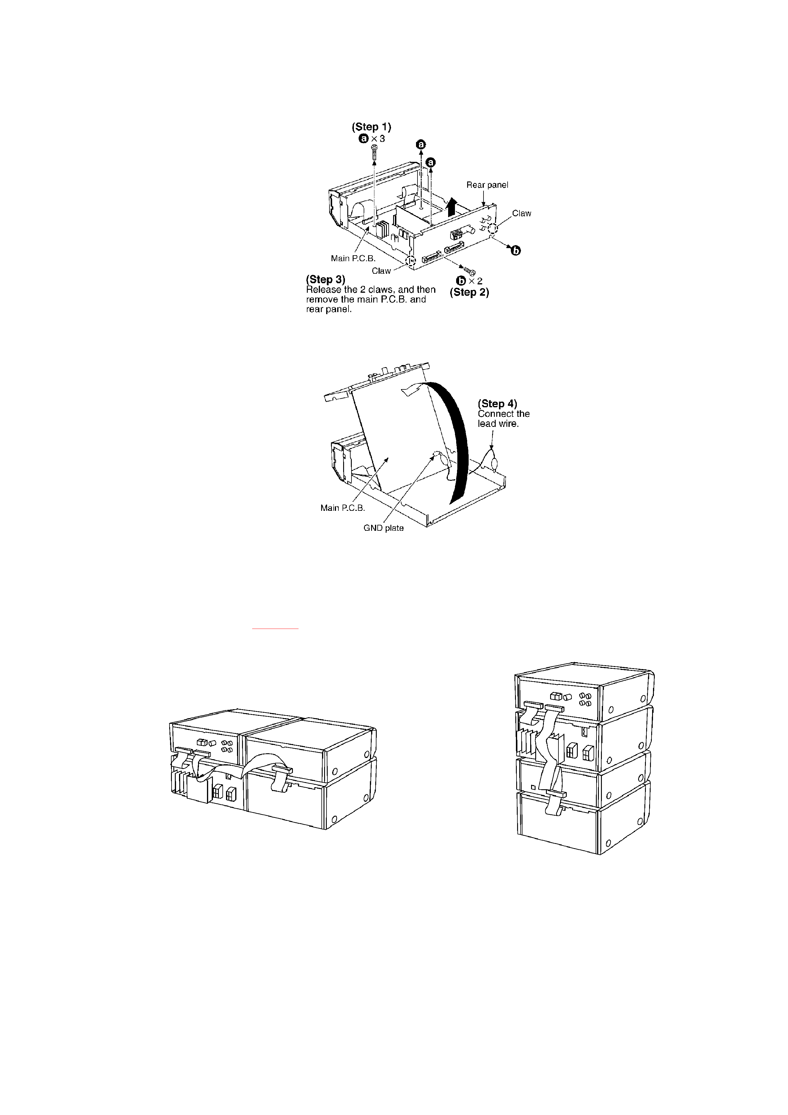
- Check the main P.C.B. as shown below.
5. To Supply Power Source
This unit is designed to operate on power supplied from system connected. / When a
component requires service, use the system connections to supply power source. / For system
connections, refer to Fig.5-1.
Fig. 5-1.
6. Self-Diagnostic Function
This unit is equipped with a self-diagnostic function which, in the event of a malfunction,
automatically displays a code indicating the nature of the malfunction.
Use this self-diagnostic function when servicing the unit.
6.1. To display the malfunction code
3
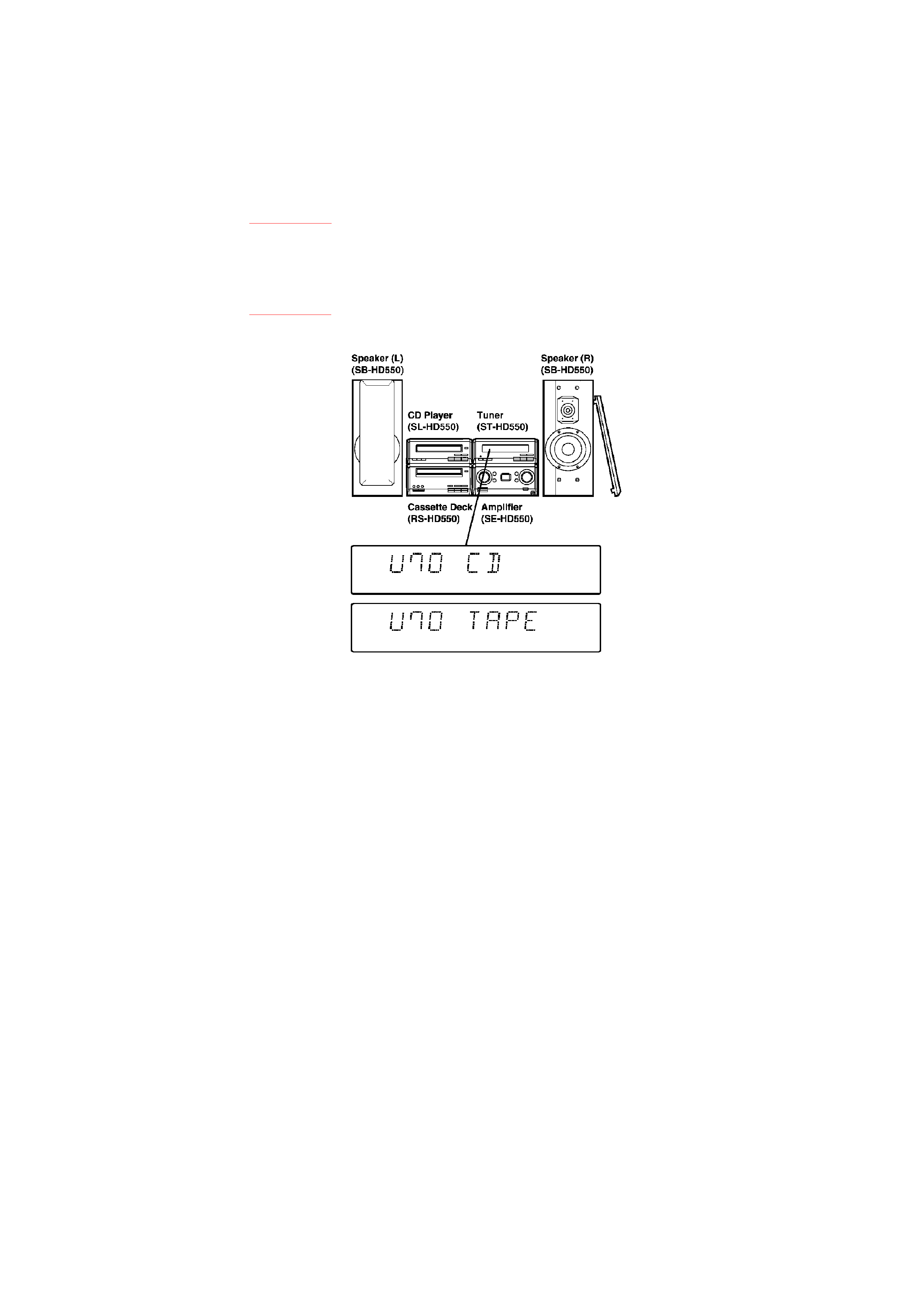
U70 CD: / U70 TAPE:
Automatically displays on the tuner when a malfunction occurs.
Refer to Fig. 6-1.
F61:
Automatically displays on the tuner when a malfunction occurs.
Refer to Fig. 6-1.
Fig. 6-1.
6.2. To return to the normal display
1. For U70 CD/U70 TAPE
- Press an any operation button on the tuner.
- To re-display the code, switch the power off (POWER
STANDBY button), and then switch power back on again.
2. For F61
- If F61 is displayed, the power will automatically be switched
off.
- F61 will be displayed for 3 seconds, and then the clock will be
displayed.
- To re-display the code, switch the power on. F61 will be re-
displayed, and then after 3 seconds the clock will be
displayed and the power will automatically switch off.
6.3. Display contents
6.3.1. U70 CD/U70 TAPE / (displayed automatically)
4
- Problem or condition
A bus-line communications error has occurred as a result of the
flat cables being inserted incorrectly, thus preventing the system
from operating.
- If U70 is displayed on the tuner, the CD Player or Cassette deck
cannot be operated by remote control.
- Correction Procedure
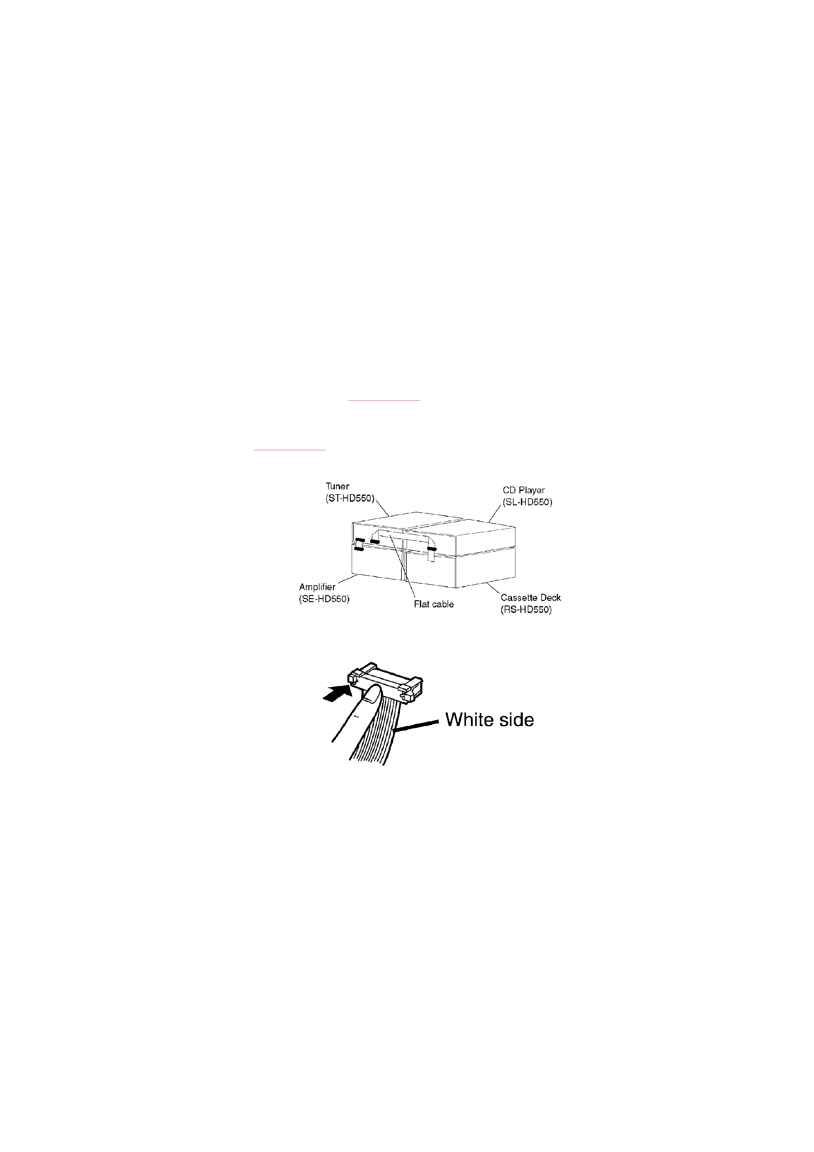
1. To check for correct insertion of the flat cables.
- Insert each connectors until you hear a click.
- Insert the flat cables at the back of the unit in the order
indicated. Refer to Fig. 6-2.
Make sure the white side of the cable is on your right side.
Refer to Fig. 6-3.
Fig. 6-2.
Fig. 6-3.
2. Breakage of the flat cables. (Check and replace.)
3. If the problem is not corrected by items 1 and 2 above, this
indicates a faulty IC.
ST-HD550:
IC601 (C2BBGF000267)
SL-HD550:
IC201 (C2BBFD000248)
RS-HD550:
IC701 (C2BBED000031)
Check these ICs and replace.
5