ORDER NO. AD9909219A2
Amplifier
SE-HD301
Colour
(N).......................Gold Type
Area
EP.......................East Europe.
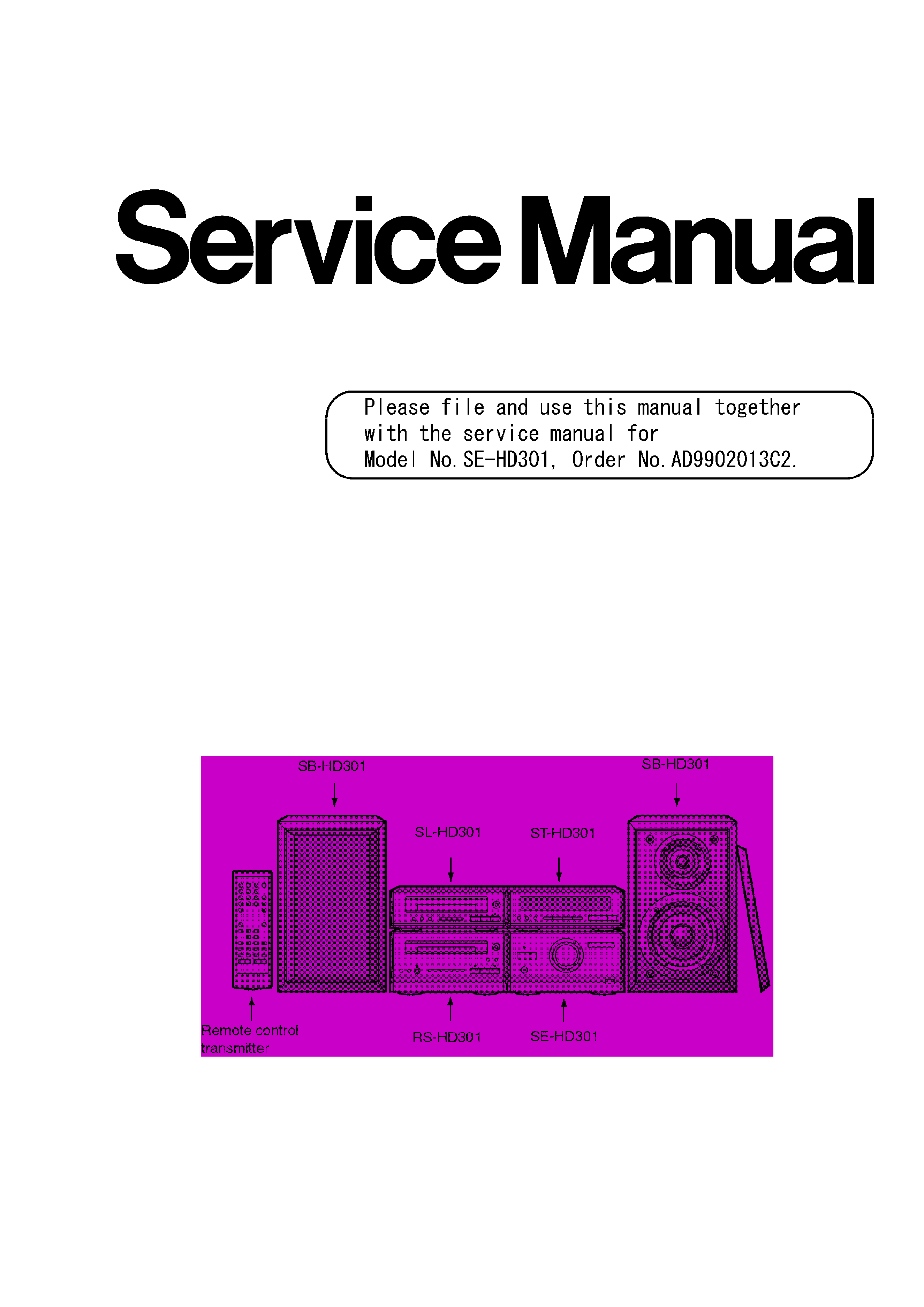
System: SC-HD301
Because of unique interconnecting cables, when a
compact requires service, send or bring in the entire
system.
SPECIFICATIONS
Specification
1

Amplifier Section (Low frequency
side)
Power output
DIN 1 kHz, THD 1%, 6
both
channels driven:
2x17W
RMS 1 kHz, THD 10%, 6
both
channels driven:
2x20W
Total harmonic distortion
Half power at 1 kHz 6
:
0.09%
Frequency response:
50-
20000Hz (+
1dB, -3dB)
Load impedance:
6
S/N:
75dB
Headphones
Jack type:
3.5mm
STEREO
Load impedance:
16-32
General
Power consumption:
67W
STANDBY condition
Normal:9W
Eco:0.8W
Power supply
AC230V,50Hz
Dimensions (WxHxD):
186x104x270mm
Weight:
2.9kg
Notes:
1.Design and specifications are subject to
change without notice.
2.Dimensions and Weight are approximate.
3.Total harmonic distortion is measured by the
digital spectrum analyzer.
System/SC-HD301:
Tuner:ST-HD301, Compact Disc Player: SL-
HD301, Amplifier: SE-HD301, Cassette Deck:RS-
HD301, Speakers: SB-HD301 (Made in MAES.)
1
2

1. Simplement Guide
This simplified Service Manual is provided to indicate the main difference between
the original model No. SE-HD301(E) and the subsequent model No.SE-HD301(EP).
- Accessories
- Operating Instructions
- Operation Checks and Component Replacement Procedures
- Power Source ON/OFF and Signal Check
- Type Illustration of IC's, Transistors and Diodes
- Schematic Diagram
- Block Diagram
- Wiring Connection Diagram
- Replacement Parts List
- Cabinet Parts Location
- Packaging
About these items written above, refer to original Service Manual SE-HD301(E)
(ORDER NO.AD9902013C2).
2. Before Repair and Adjustment
1. Turn off the power supply. Using a 10
, 10W resistor, connect both ends of power
supply capacitors (C102-105, 127) in order to discharge the voltage.
2. Before turning the power supply on, after completion of repair, slowly apply the
primary voltage by using a power supply voltage controller to make sure that the
consumed current at 50 Hz in NO SIGNAL mode should be shown below with
respect to supply voltage 230 V.
Area
(EP)
Power supply voltage
AC 230V
Consumed current
50 Hz
30-140 mA
3. Printed Circuit Board Diagram
3
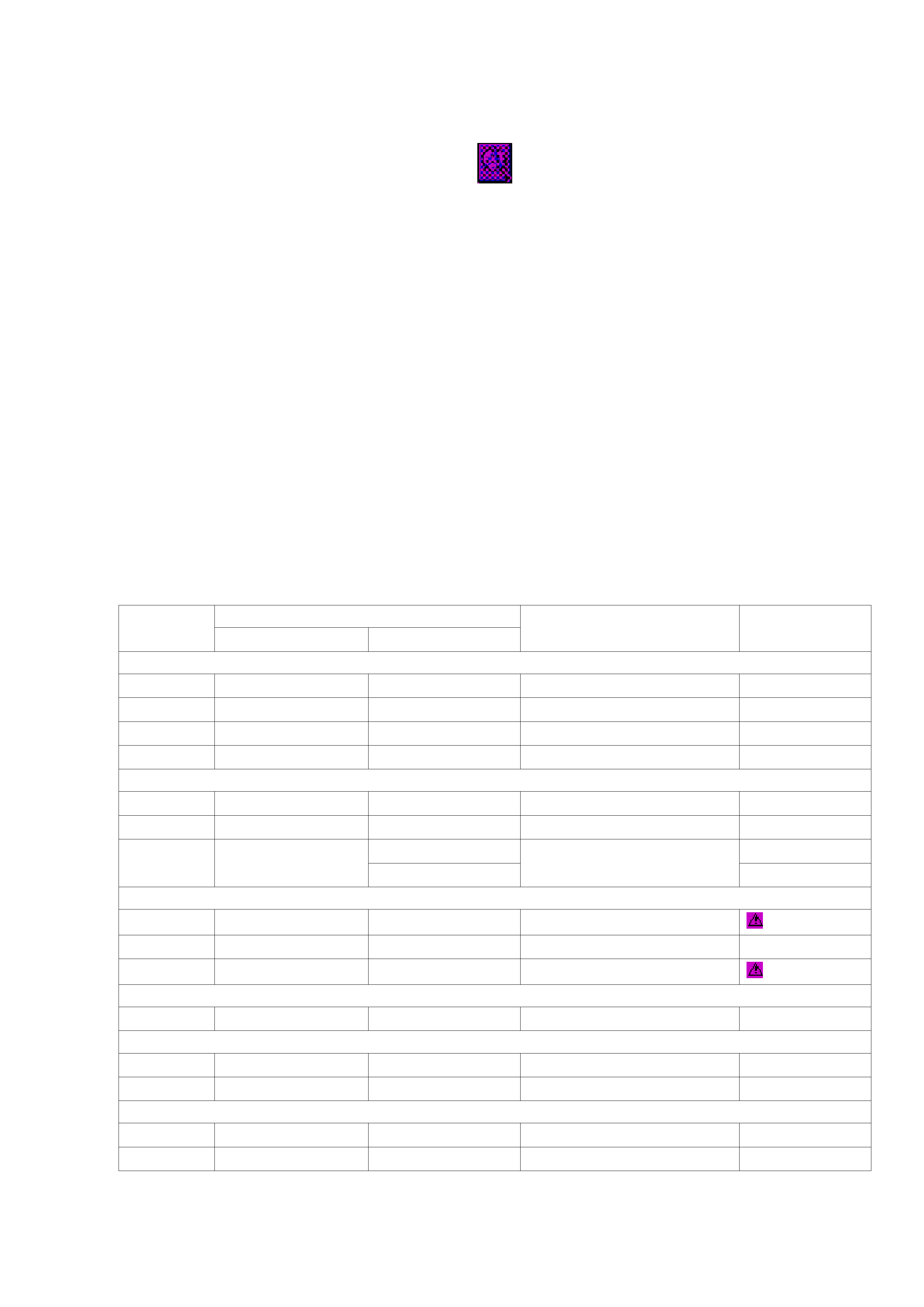
4. Change in Replacement Parts List [Refer to pages 22-
24 of SE-HD301(E) Service Manual.]
Notes:
*Mentioned in this parts list is only those different from Model No.SE-HD301(E)
All other parts are the same as for SE-HD301(EP).
*Important safety notice:
Special parts which have purposes of fire-retardant (resistors), high-quality sound
(capacitors), low-noise (resistors), etc. are used.
When replacing any of components, be sure to use only manufacture's specified
parts shown in the parts list.
* "<IA>, <IB>" marks in Remarks indicate languages of instruction manuals.
[<IA>:Polish/Czeco,<IB>:English ]
Ref No.
Change of Part No.
Part Name & Description
Remarks
SE-HD301(E)
SE-HD301(EP)
CABINET AND CHASSIS
2
RKM0397B-S
RKM0397B-S1
CABINET
5
RGH0154B-K
RGH0154J-K
NAME PLATE
7
RKA0076-N1
RKA0076-N3
FOOT
27
RMV0186
--
BARRIER
Deletion
ACCESSORIES
A4
RQA0117
--
WARRANTY CARD
Deletion
A5
RQCB0169
--
SERVICENTER LIST
Deletion
A6
RQT4890-E
RQT5202-R
INSTRUCTION MANUAL
<IA>
RQT4891-2B
<IB>
CAPACITOR(S)
C104, 105
ECA1HM470B
ECA1HM470
50V 47U
C126
ECA1HM470B
ECA1HM470
50V 47U
C705
ECA1HM470B
ECA1HM470
50V 47U
JACK
JK301
RJJ37TN01-C
RJJ37TN01-2C
JACK, HEADPHONES
PACKING MATERIALS
P4
RPG4322
RPG4669
PACKING CASE (SYSTEM)
P5
RPQ0771
RPQ0952
PAD
PRINTED CIRCUIT BOAD
PCB1
--
REP2812A-M
MAIN P.C.B.
Addition (RTL)
PCB2
--
REP2813A-S
OPERATION P.C.B.
Addition (RTL)
4

Printed in Japan (H990902500TN/HH)
1
1999 Matsushita Electric Industrial Co., Ltd.
All rights reserved. Unauthorized copying and distribution is a
violation of law.
5