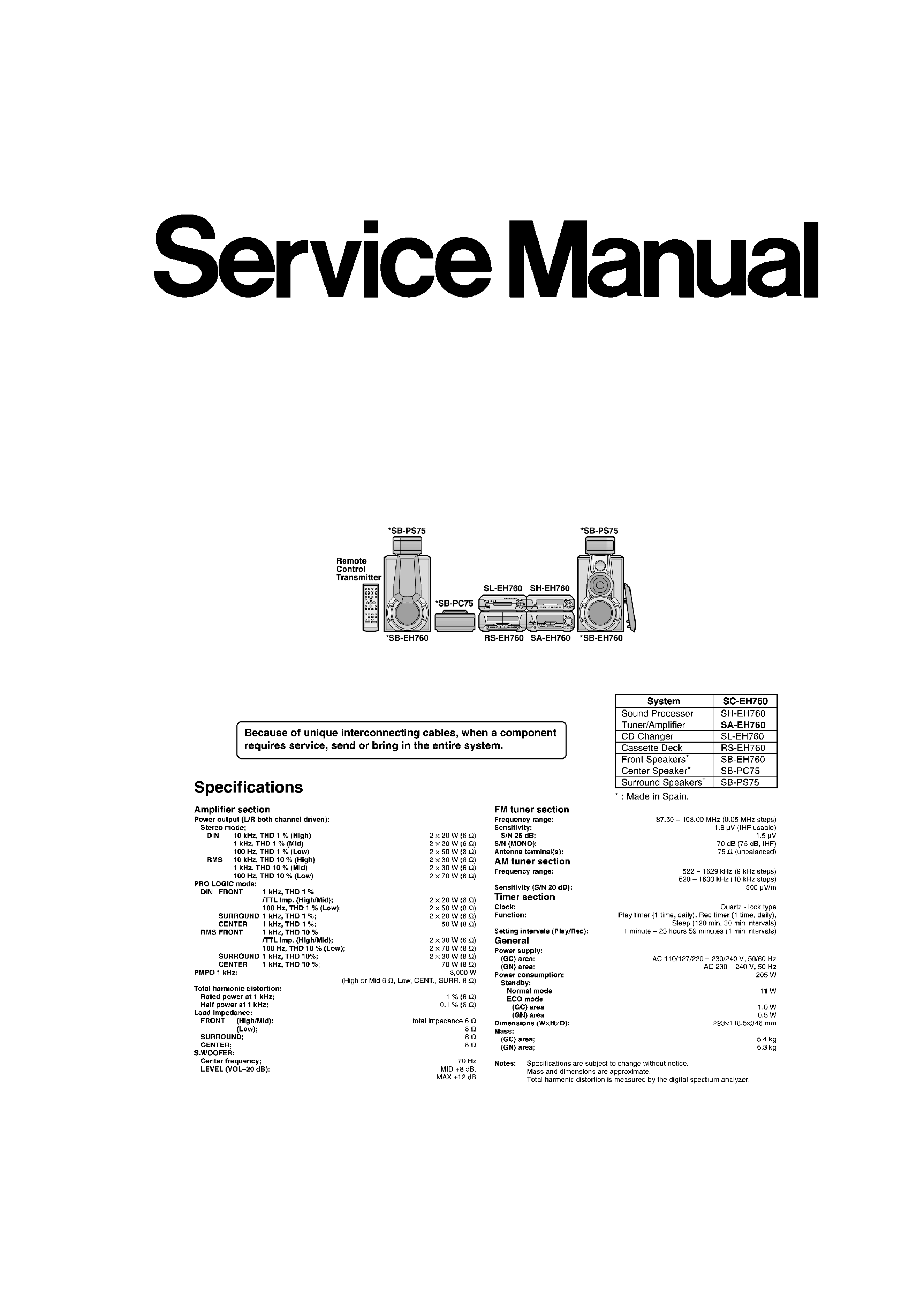
AD0004083C3
Tuner/Amplifier
SA-EH760
Colour
(S)....................Silver Type
Areas
(GC)..................Asia, Latin America, Middle Near East and Africa.
(GN)..................Oceania.
SPECIFICATIONS
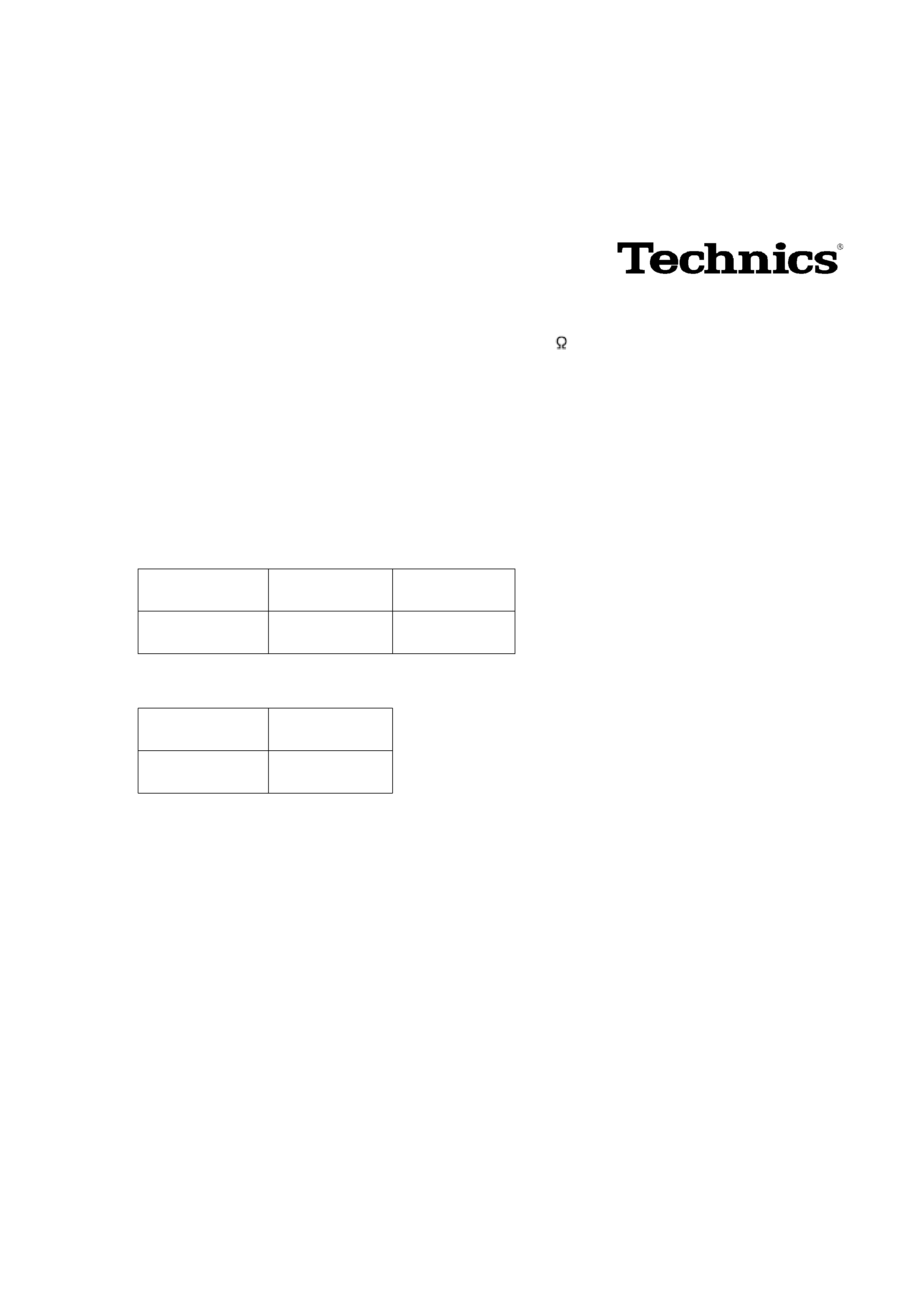
1. Before Repairs
1. Turn off the power supply. Using a 10
, 10 W resistor, connect
both ends of power supply capacitors (C701, C703 and C702,
C704) in order to discharge the voltage.
2. Before turning the power supply on, after completion of repair,
slowly apply the primary voltage by using a power supply voltage
controller to make sure that the consumed current at 50 Hz in NO
SIGNAL mode should be shown below.
For (GC) area
Power supply
voltage
AC 110 V, 50 Hz AC 240 V, 50 Hz
Consumed
current
200-700 mA
100-350 mA
For (GN) area
Power supply
voltage
AC 240 V, 50 Hz
Consumed
current
100-350 mA
2. Protection Circuitry
The protection circuitry may have operated if either of the following conditions is noticed:
- No sound is heard when the power is switched ON.
- Sound stops during a performance.
The functions of this circuitry is to prevent circuitry damage if, for example, the positive and
negative speaker connection wires are shorted, or if speaker systems with an impedance less
than the indicated rated impedance of this unit are used.
If this occurs, follow the procedures outlined below.
1. Switch OFF the power.
2. Determine the cause of the problem and correct it.
3. Switch ON the power once again.
Note:
2
When the protection circuitry functions, the unit will not operate
unless the power is first switched OFF and then ON again.
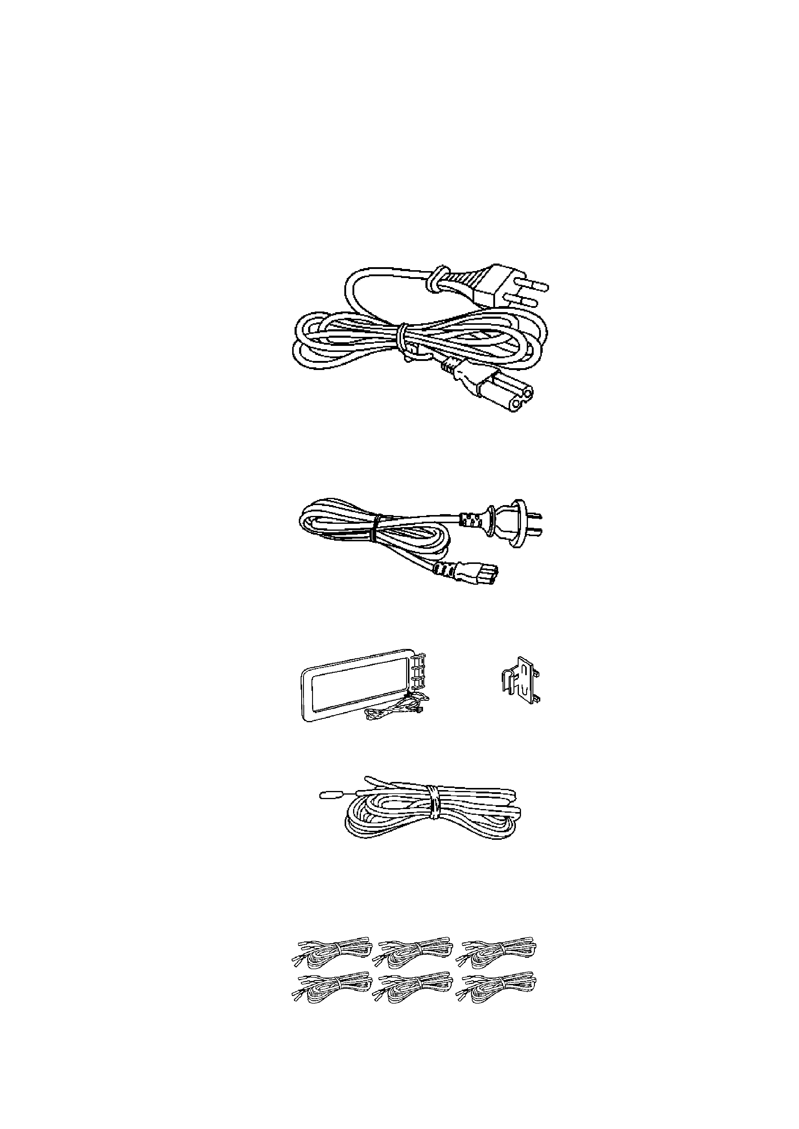
3. Accessories
- AC power supply cord for (GC) area / (RJA0019-X)...........................1
pc.
- AC power supply cord for (GN) area / (RJA0035-X)...........................1
pc.
- AM loop antenna set / (RSA0022-J)...........................1 pc.
- FM indoor antenna / (RSA0006-J)............................1 pc.
- Speaker cords / (REE0393)..............................2 pcs. /
(REE0984)..............................2 pcs. / (REE0985)..............................2
pcs.
3
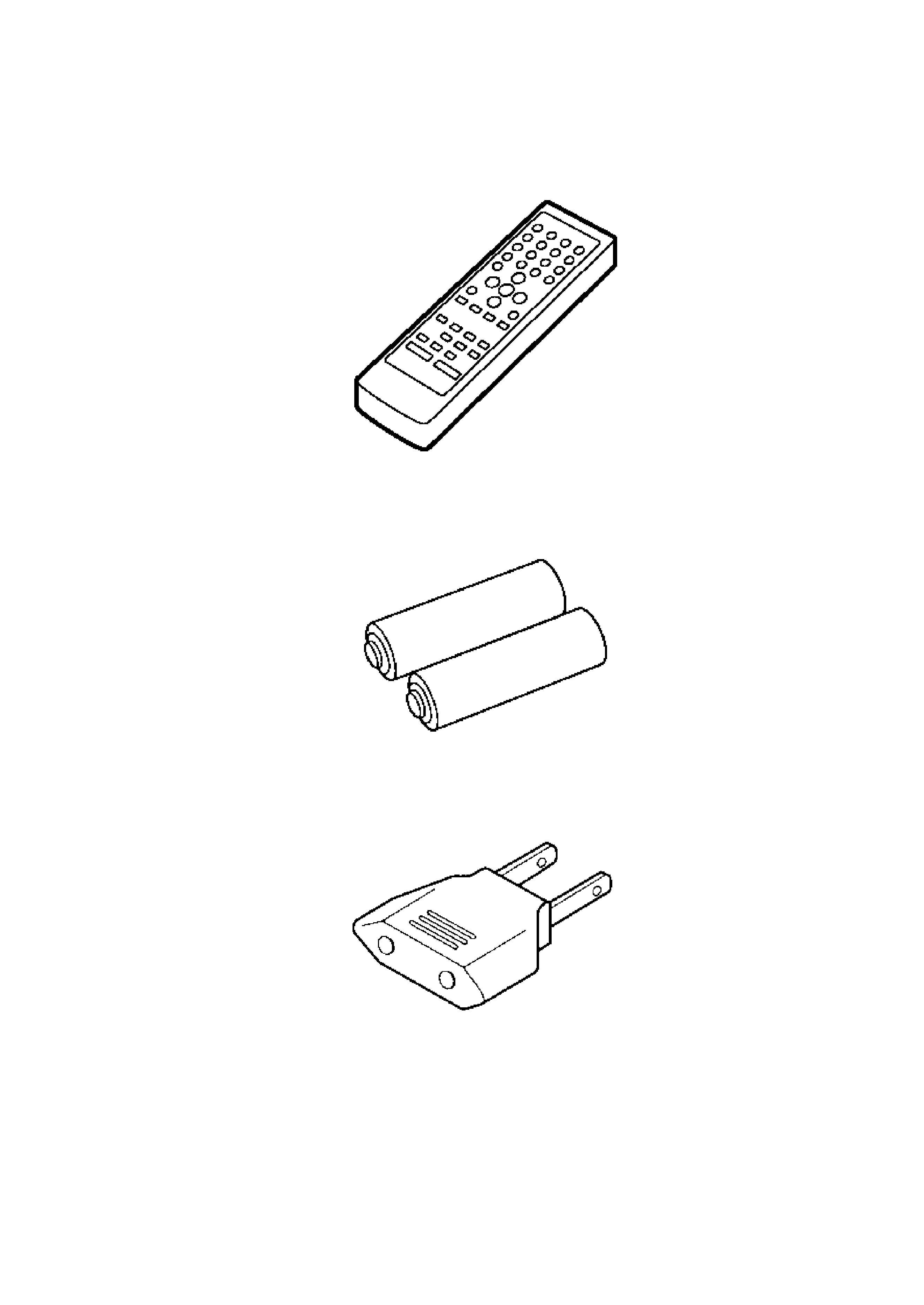
- Remote control transmitter / (RAK-EHA28WH)..................1 pc.
- Remote control batteries / (R6/LR6, "AA", UM-3)...........2 pcs.
Note: These are available on sales route.
- Power plug adaptor for (GC) area only / (SJP5213-
2)...........................1 pc.
4. Location of Controls
5. Operation Checks and Component Replacement
Procedures
4
- This section describes procedures for checking the operation of
the major printed circuit boards and replacing the main
components.
- For reassembly after operation checks or replacement, reverse the
respective procedures. Special reassembly procedures are
described only when required.
/
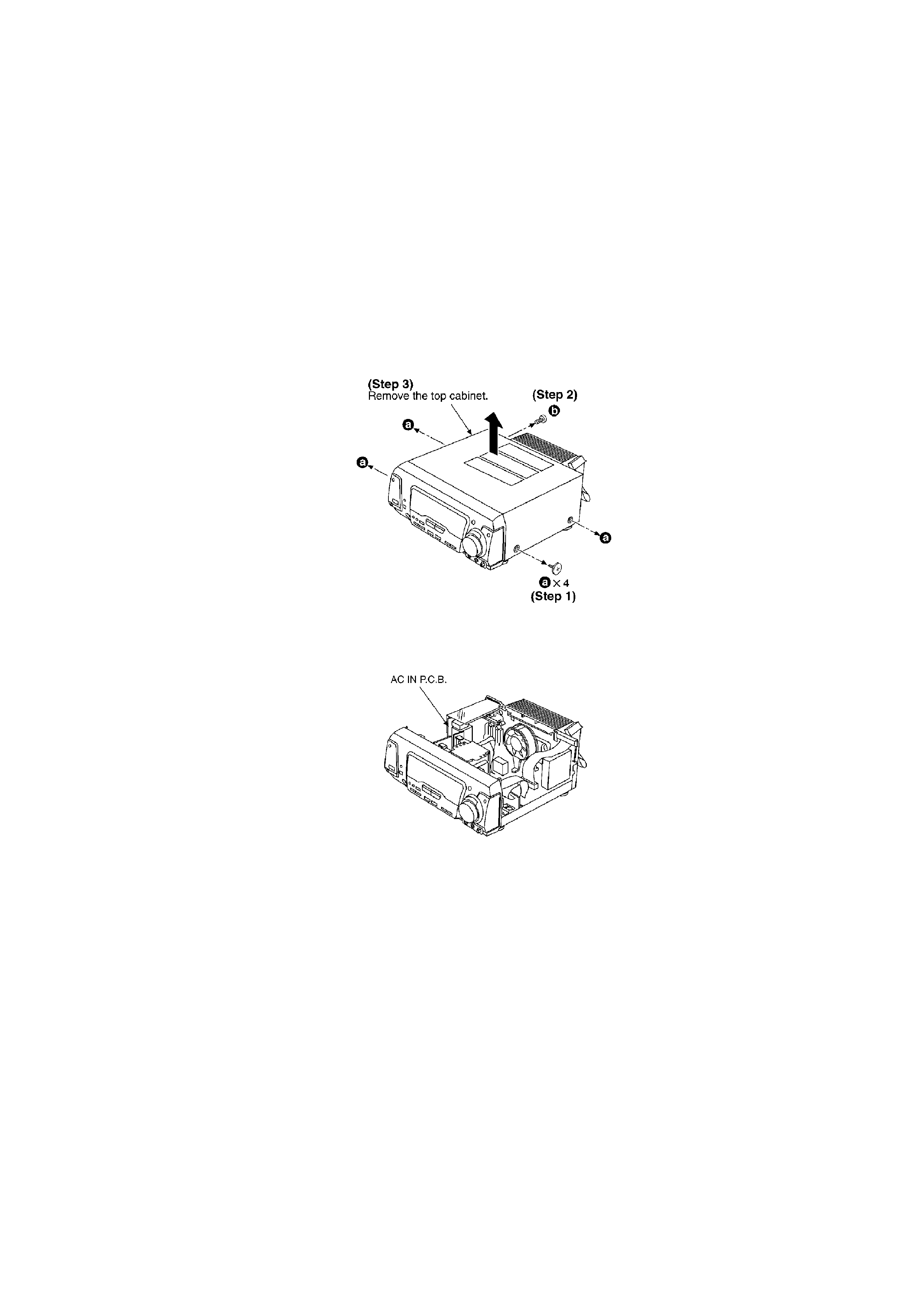
5.1. Checking for the AC IN P.C.B.
- Check the AC IN P.C.B. as shown below.
5.2. Checking for the operation P.C.B.
- Follow the (Step 1) - (Step 3) of item 5.1.
5