SSRR--LL3300D
DA
ABB
SERVICE MANUAL
DAB/FM Stereo Radio
Effective : January, 2004
S-0110A
NOTES
PC boards shown are viewed from parts side.
The parts with no reference number or no parts number in the
exploded views are not supplied.
As regards the resistors and capacitors, refer to the circuit diagrams
contained in this manual.
£
Parts marked with this sign are safety critical components. They
must be replaced with identical components - refer to the appropriate
parts list and ensure exact replacement.
CONTENTS
1 SPECIFICATIONS
2
2 MICROCOMPUTER PIN FUNCTIONS
3
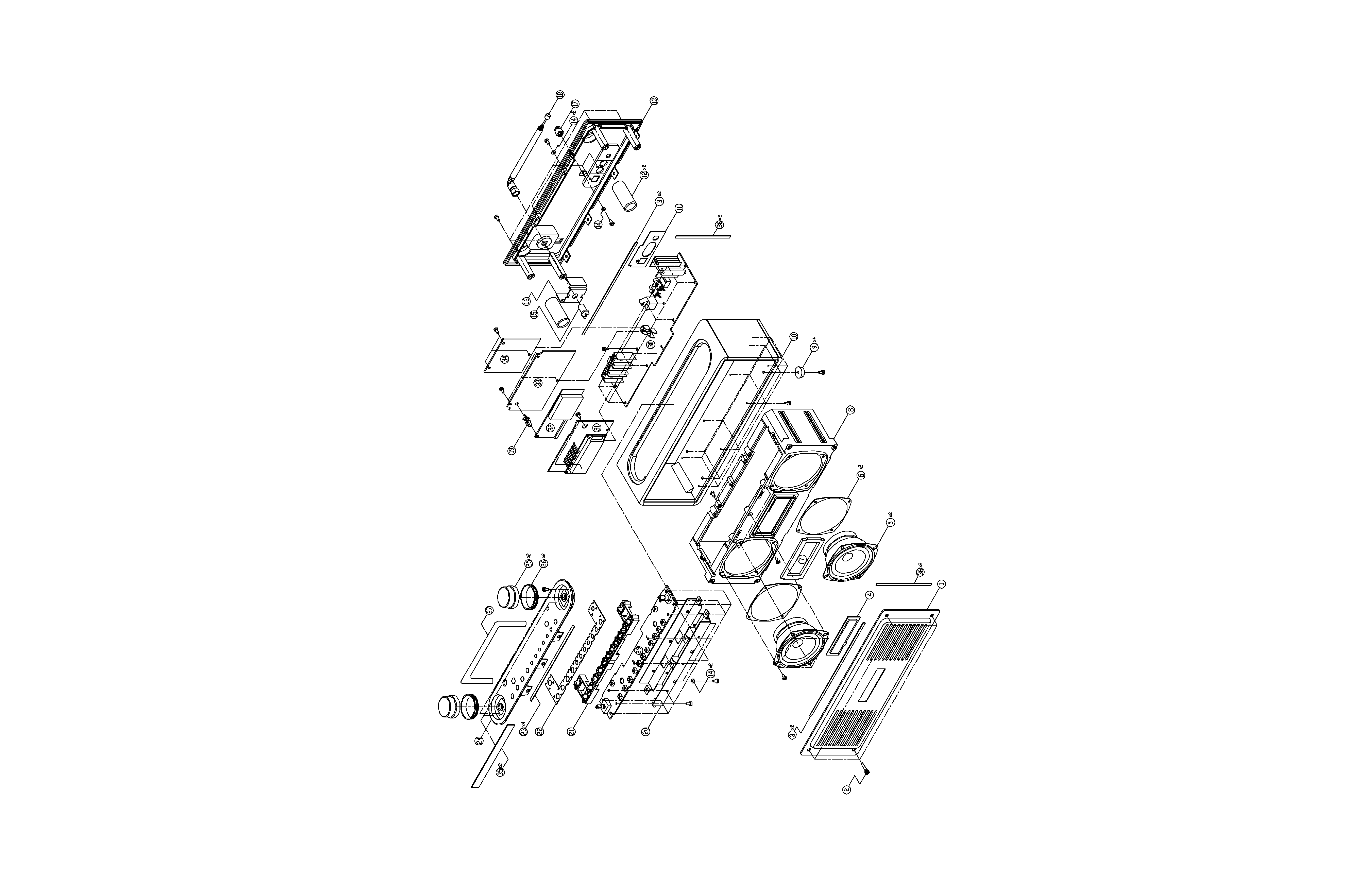
3 EXPLODED VIEWS AND PARTS LIST
5
4 PC BOARDS AND PARTS LIST
7
For U.K.
1 SPECIFICATIONS
2
FM Tuner
Tuning range ..........................87.50 - 108.00 MHz (50 kHz steps)
Signal-to-Noise ratio ......................65 dB (Mono), 60 dB (Stereo)
DAB Tuner
Tunig range ......................................Band 3, 174 MHz - 240 MHz
Input ................................................................Telescopic antenna
Max signal .................................................................. 3 dBm typ
Sensitivity .................................................................. 96 dBm typ
Adjacent channel rejection ..............................................35 dB typ
Digital output ............................................24 bit/48 kHz resolution
Speaker System
Unit ......................................................................7.5 cm Cone x 2
Connectors
Digital output..................................................................Optical x 1
Analogue audio output ......................................................RCA x 1
Headphone out....................................3.5 mm stereo mini jack x 1
General
Output power ................................................................2 W + 2 W
Power requirements..........................................................DC +12V
Dimensions (W x H x D) ..................................310 x 146 x 95 mm
Weight ..................................................................................2.0 kg
Operating temperature ................................................0 °C - 50 °C
Accessories
AC adaptor x 1
· Design and specifications are subject to change without notice.
About DAB
With this unit you can receive and listen to Digital Audio
Broadcast (DAB) programmes. DAB uses digital, not analogue
signals, resulting in near CD-quality audio with virtually
interference-free reception. Along with superior quality audio,
DAB can also deliver additional audio channels and text. In the
future, computer data and images are also possible.
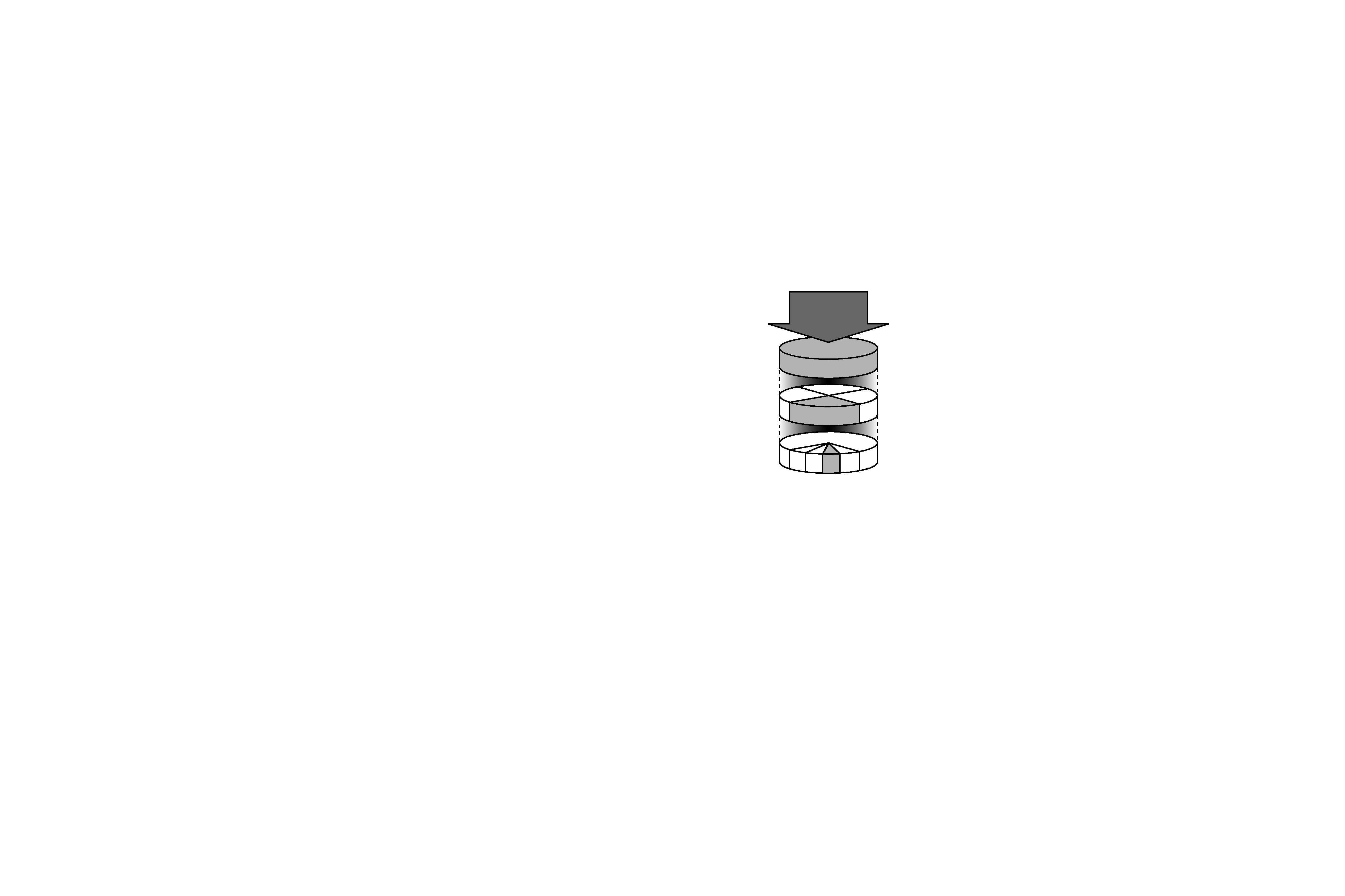
Digital radio is broadcast as groups of data called ensembles or
multiplexes. Each multiplex can contain a number of stations
(services) and each station contains a primary service and can
contain secondary services as illustrated in the following diagram.
Each multiplex is transmitted in a set frequency range and
received by this unit for decoding. You can receive multiplexes
broadcast in the 174240 MHz frequency band and store the
services in each multiplex for you to access. The number of
multiplexes you receive depend on your location. Channels used
in the UK are in the range 10A to 12D.
Multiplexes and stations have labels (names) that are used to
identify them. Instead of needing to know the particular frequency
of your favourite broadcast, you can simply select the station
name. Secondary services and additional data such as text or
multiplex info are also available.
DAB SIGNAL
MULTIPLEX
PRIMARY
SERVICES
SECONDARY
SERVICES
Parliament
BBC Radio 4
BBC
National
DAB
1
1
2
3+
1
2
3
4+
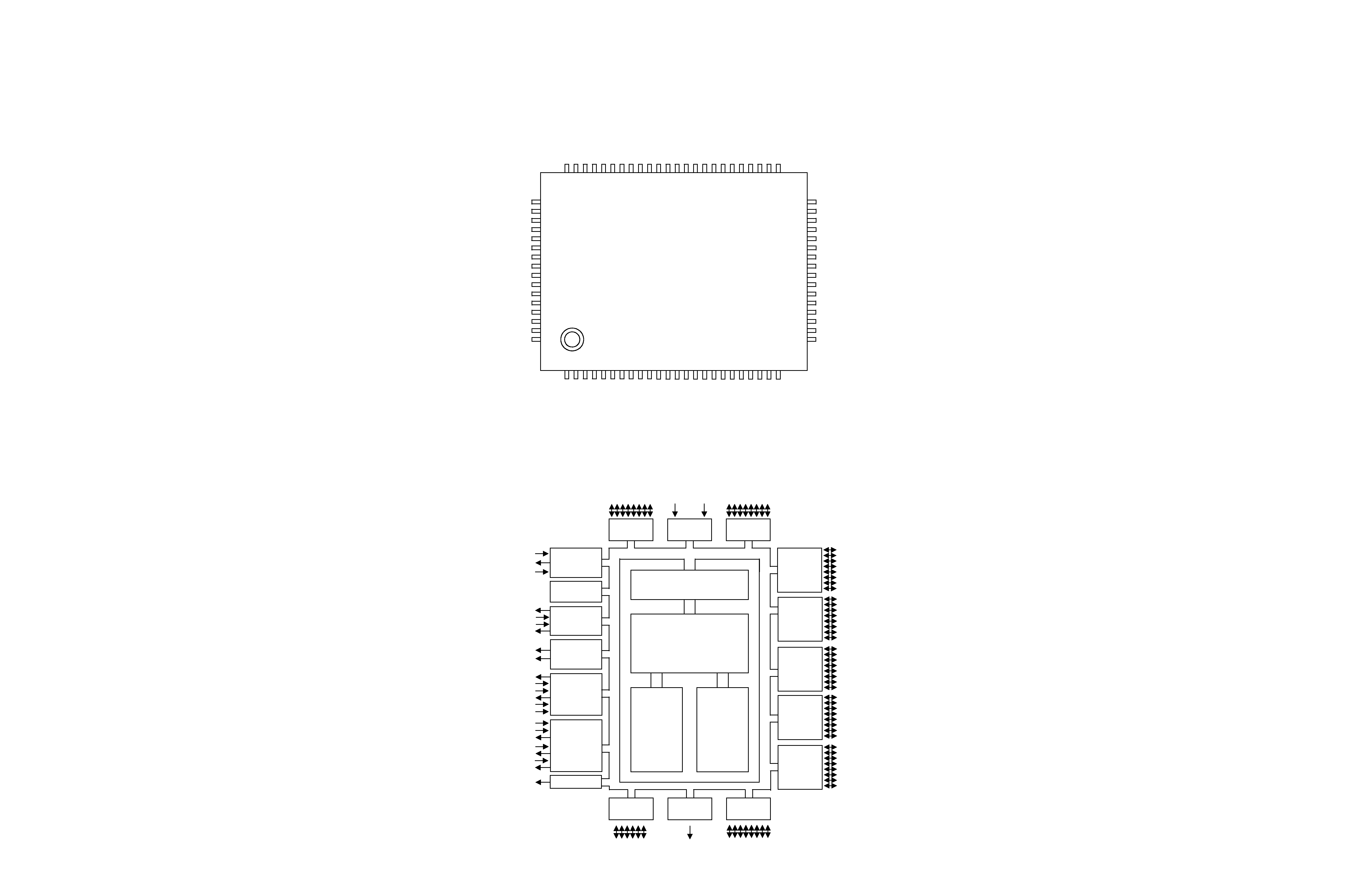
2 MICROCOMPUTER PIN FUNCTIONS
3
P1.7
P1.6
P1.5
P1.4
P1.3
P1.2
P1.1
P1.0
P0.7/PG7
P0.6/PG6
P0.5/PG5
P0.4/PG4
P0.3/PG3
P0.2/PG2
P0.1/PG1
P0.0/PG0
P2.7/T
AO
UT
P2.6/TACAP
P2.5/
T
ACK
P2
.4/T
BPW
M
P2
.3/DAO
U
T
P2.
2/SCK
P2.1/SI
P2
.0/SO
P5.7
P5.6/
SDAT
P5.5/
SCLK
VDD1
VSS1
XO
U
T
XI
N
T
EST
P5.4
P5.3
/Rx
D
0
RE
SETB
P5.2
/T
x
D
0
P5.1
/Rx
D
1
P5.0
/T
x
D
1
P
3.7/T
CO
U
T
1
P
3.6/T
CO
U
T
0
S3C84BB/F84BB
(80-QFP-1420C)
64
63
62
61
60
59
58
57
56
55
54
53
52
51
50
49
48
47
46
45
44
43
42
41
1
2
3
4
5
6
7
8
9
10
11
12
13
14
15
16
17
18
19
20
21
22
23
24
65
66
67
68
69
70
71
72
73
74
75
76
77
78
79
80
25
26
27
28
29
30
31
32
33
34
35
36
37
38
39
40
P3.5/T1OUT1
P3.4/T1OUT0
P3.3/T1CAP1
P3.2/T1CAP0
P3.1/T1CK1
P3.0/T1CK0
P4.7/INT7
P4.6/INT6
P4.5/INT5
P4.4/INT4
P4.3/INT3
P4.2/INT2
P4.1/INT1
P4.0/INT0
P7.7/ADC7
P7.6/ADC6
P8.0
P8.1
P8.2
P8.3
P8.4/IN
T
8
P8.5/IN
T
9
P6.0
P6.1
P6.2
P6.3
P6.4
VDD2
VSS2
P6.5
P6.6
P6.7
P7.0/AD
C
0
P7.1/AD
C
1
P7.2/AD
C
2
P7.3/AD
C
3
AVSS
AVREF
P7.4/AD
C
4
P7.5/AD
C
5
2-1 Pin Assignment
I/O Port and Interrupt Control
SAM88RC CPU
64K-Byte
ROM
2064-Byte
RAM
OSC/RESETB
8-Bit
Basic Timer
8-Bit
Timer
/CounterA,B
8-Bit
Timer/
CounterC0,C1
16-Bit
Timer
/Counter10,11
Port 0
Port 1
A/D
Port 2
P2.0-P2.7
XIN
XOUT
RESETB
P2.7/TAOUT
P2.6/TACAP
P2.5/TACK
P3.6/TCOUT1
P2.4/TBOUT
P3.4/T1OUT0
P1.0-P1.7
P0.0-P0.7
AVREF
AVSS
Port 3
P3.0-P3.7
Port 4
P4.0-P4.7/
INT0~INT7
Port 5
P5.0-P5.7
Port 6
P6.0-P6.7
SIO/
UART0,1
PG
P3.7/TCOUT0
P0.0~P0.7/
PG0~PG7
P3.2/T1CAP0
P3.0/T1CK0
P3.5/T1OUT1
P3.3/T1CAP1
P3.1/T1CK1
P2.2/SCK
P2.1/SI
P2.0/SO
P5.3/RXD0
P5.2/TXD0
P5.1/RXD1
P5.0/TXD1
Port 8
Port 7
D/A
P7.0-P7.7/
ADC0~ADC7
P8.0-P8.5/
INT8,INT9
P2.3/
DAOUT
2-2 Block Diagram
4
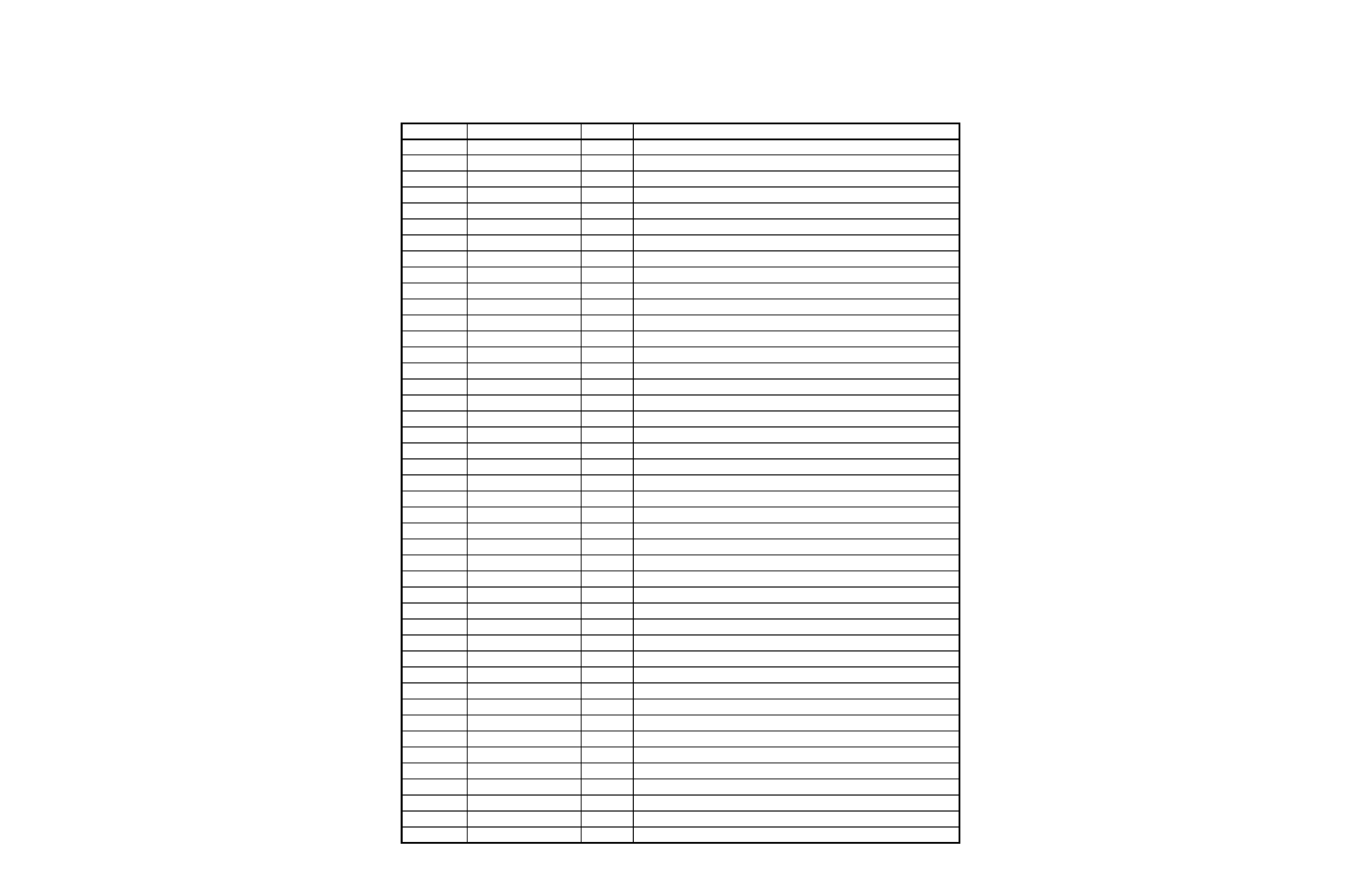
PIN No.
I/O
DESCRIPTION
1~8
O
LCD Data Bus lines
10
I
UART Data input port
11
O
UART Data output port
12
I
Power supply port (+5V)
13
-
GND
14
O
10MHz crystal connection port
15
I
16
I
Full-Down register connected internally
19
I
Reset input port ("L")
21
I
DAB Data input port
22
O
DAB Data output port
23
O
DAB Clock control port
24
O
FM MUTE control port ("L")
25
O
PLL Data output port
26
O
PLL Enable control port
27
O
PLL Clock control port
28
I
Tuner module stereo control port
29
I
Tuner module tuned control port
30
I
PLL Data input port
31
-
32
-
33
I
BACKUP mode control port ("L")
34
-
35
-
36
-
39,40
-
GND
41
I
Scroll up control port
42
I
Scroll down control port
43
I
A/D converter reference voltage
44,45
-
GND
46
I
Key 3 control port
47
I
Key 2 control port
48
I
Key 1 control port
52
-
GND
53
I
Power supply port (+5V)
54
O
System MUTE control port ("L")
55
-
56
O
DAB on control port ("H")
57
O
FM on comtrol port ("H")
58
O
Unit turn on control port ("H")
65~71
I
Option control port
78
O
Register selection (H:Data registor, L:Instruction registor)
79
O
Read/Write selection (H:Read, L:Write)
80
O
Enable signal for LCM
DAB_DIN
RESET
DAB_DOUT
DAB_CK
FM_MUTE
PLL_D
PLL_CE
PLL_CLK
NAME
VSS1
X OUT
X IN
TEST
LCD-DA
SINO
SOTO
VDD1
STEREO
TUNED
PLL_DIN
NC
NC
BACK_UP
NC
NC
NC
GND
SCROLL_UP
SCROLL_DN
VREF
AVSS
KEY 3
KEY 2
KEY 1
VSS2
VDD2
SYSTEM_MUTE
NC
DAB_ON
FM_ON
POWER_ON
OPTION
RS_P
R/W
ES_P
2-3 Pin Functions
5
3 EXPLODED VIEWS AND PARTS LIST