P
PLL--D
D220
00
0V
V
SERVICE MANUAL
VCR/DVD HOME THEATER SYSTEM
Effective : September, 2003
S-0000A
CAUTION
£
Parts marked with this sign are safety critical components. They
must be replaced with identical components - refer to the appropriate
parts list and ensure exact replacement.
Before returning appliance to the customer, make leakage-current or
resistance measurements to determine that exposed parts are
acceptably insulated from the supply circuit.
CONTENTS
SPECIFICATIONS
2
DISASSEMBLY
6
PRINCIPAL PARTS LOCATION
7
BLOCK DIAGRAM
9
TROUBLE SHOOTING
11
PRINTED CIRCUIT BOARDS
15
WIRING DIAGRAM
29
EXPLODED VIEW
31
ELECTRICAL PARTS LIST
43
IC INTERNAL DIAGRAMS
88
IC AND TRANSISTOR VOLTAGE CHART
131
SCHEMATIC DIAGRAMS
141
ADJUSTMENT METHOD
155

2
SPECIFICATIONS
AMPLIFIER Section
Output Power (6 ohms, 1KHz, 1% T.H.D) : Stereo
Front L/R
(2 Channel Driven)
45W x 2ch
Output Power (6 ohms, 1KHz, 1% T.H.D)
Front L/R
(2 Channel Driven)
45W x 2ch
Center
(1 Channel Driven)
45W x 1ch
Rear L/R
(2 Channel Driven)
45W x 2ch
Subwoofer (1 Channel Driven)
45W x 1ch
S/N Ratio (IHF-A Weighted)
1 Channel Driven
>65dB
Frequency Response
Front L/R (Large)
120~20KHz (-3dB point)
Center (Large)
120~20KHz (-3dB point)
Rear L/R (Large)
120~7KHz (-3dB point)
Subwoofer
10~150Hz (-3dB point)
Tone Control
Bass (100Hz)
±6dB
Treble (10KHz)
±6dB
Input Sensitivity
Stereo (1KHz)
260mV~360mV
CH Separation
Stereo (1KHz)
> 50dB
FM TUNER Setion
Frequency Range
87.5~108 MHz
Sensitivity
Mono
8uV/m, EMF
Distortion
Mono
0.5%
Stereo
1%
S/N Ratio
Mono
65dB
Stereo
60dB
DVD Section (TDV-540)
Composite Output Level
1.0V (p-p), 75ohm
S-Video Y-Output Level
1.0V (p-p), 75ohm
S-Video C-Output Level
280mV (p-p), 75ohm
VCR (audio) Section [Hi-Fi]
Output Level
Audio -8dBm (E.E)
-8±2dBm
Distortion (T.H.D)
Audio -8dBm (SP)
1.0
%
Audio -8dBm (LP/SLP)
1.5
%
S/N Ration
Audio -8dBm (E.E)
50
%
Audio -8dBm (SP)
55
%
Audio -8dBm (LP/SLP)
55
%
VCR (video) Section
E.E Video Level
1.0±0.2V
SRP SYNC Level
0.3±0.03V
SRP BURST Level
0.3±0.03V
SRP Video Level
1.0±0.2V
GENERAL
Power Consumption
110W
Weight (Main unit)
9.42Kg
Dimension (WxHxD)
430x107x422
NOTE: Design and specifications are subject to change and improvement without notice
3
SAFETY PRECAUTIONS
The following check should be performed for the continued
protection of the customer and service technician.
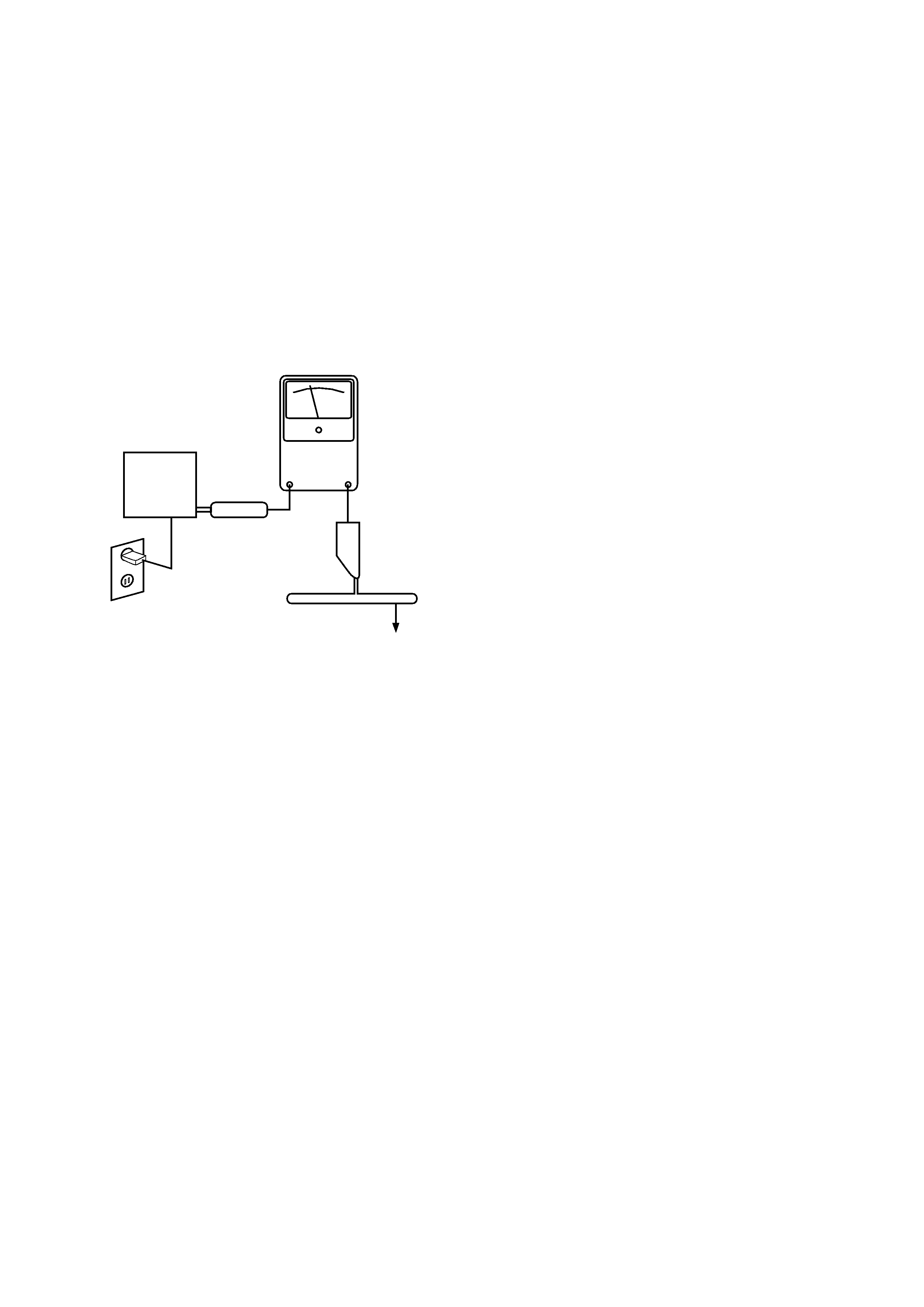
LEAKAGE CURRENT CHECK
Measure leakage current to a known earth ground (water
pipe, conduit, etc.) by connecting a leakage current tester
between the earth ground and all exposed metal parts of the
appliance (input/output terminals, screwheads, metal
overlays, control shaft, etc.). Plug the AC line cord of the
appliance directly into a 120V AC 60Hz outlet and turn the
AC power switch on. Any current measured must not exceed
0.5mA.
ANY MEASUREMENTS NOT WITHIN THE LIMITS
OUTLINED
ABOVE
ARE
INDICATIVE
OF
A
POTENTIAL SHOCK HAZARD AND MUST BE
CORRECTED BEFORE RETURNING THE APPLIANCE
TO THE CUSTOMER.
Device
under
test
Test all
exposed metal
surfaces
Also test with
plug reversed
(Using AC adapter
plug as required)
AC Leakage Test
Leakage
current
tester
Reading should
not be above
0.5mA
Earth
ground
4
LASER BEAM SAFETY PRECAUTIONS
CLASS 1 LASER PRODUCT
DANGER
INVISIBLE LASER RADIATION
AVOID DIRECT EXPOSURE TO BEAM
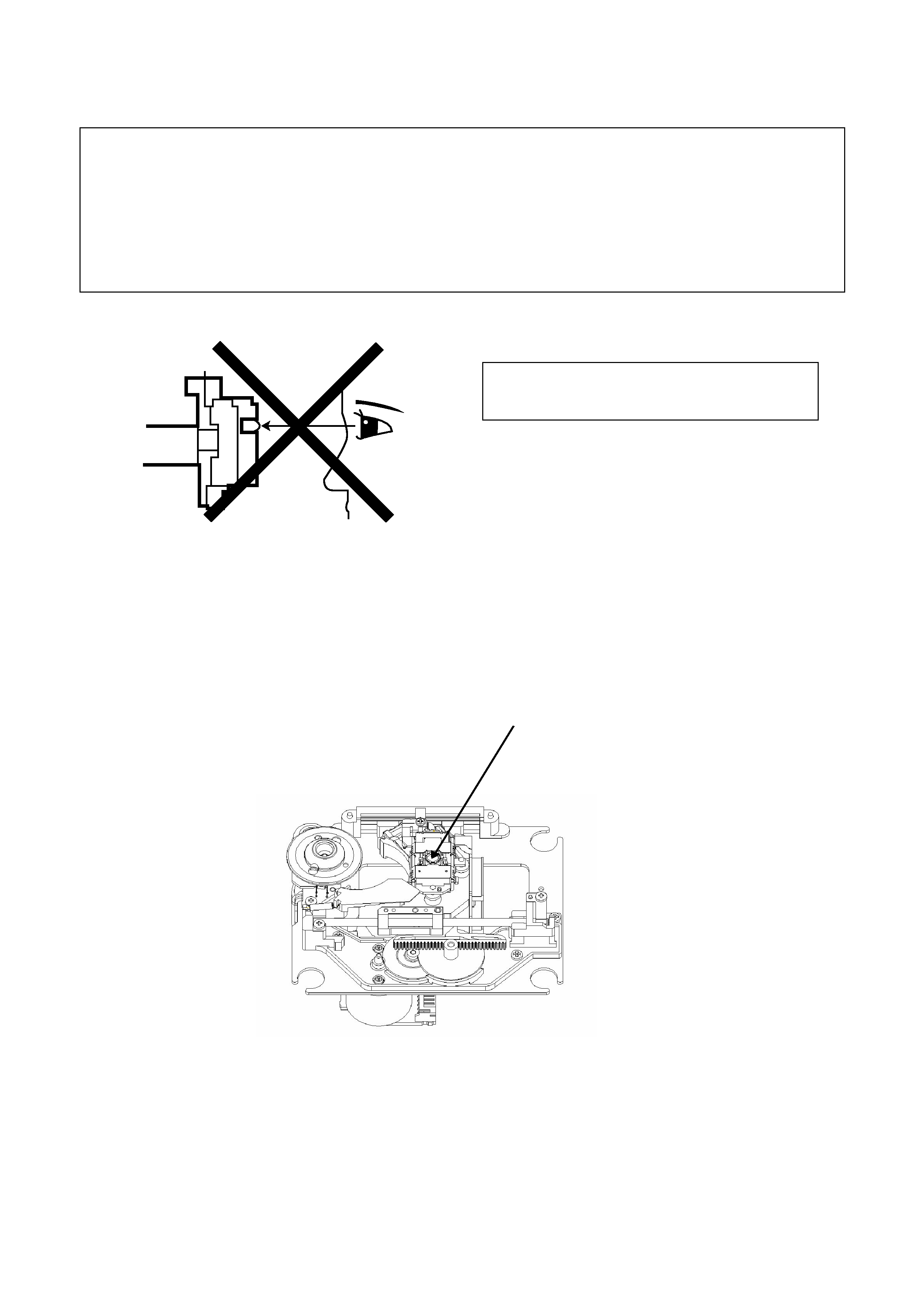
This Receiver uses a pickup that emits a laser beam.
The laser beam is emitted from the location shown in the figure. When checking the laser diode, be sure to keep your eyes
at least 1 foot away from the pickup lens when the diode is turned on. Do not look directly at the laser beam.
Caution: Use of controls and adjustments, or doing procedures other than those specified herein, may result in hazardous
radiation exposure.
Do not look directly at the laser beam coming
from the pickup or allow it to strike against your
skin.
Laser Beam Radiation
5
HANDLING LASER PICKUP
The laser diode in the optical system of this receiver can be damaged by electrostatic discharge from clothes,
body, etc. Proper electrostatic grounding for service personnel is required during servicing.
BEFORE REPAIRING THE DVD MECHANISM
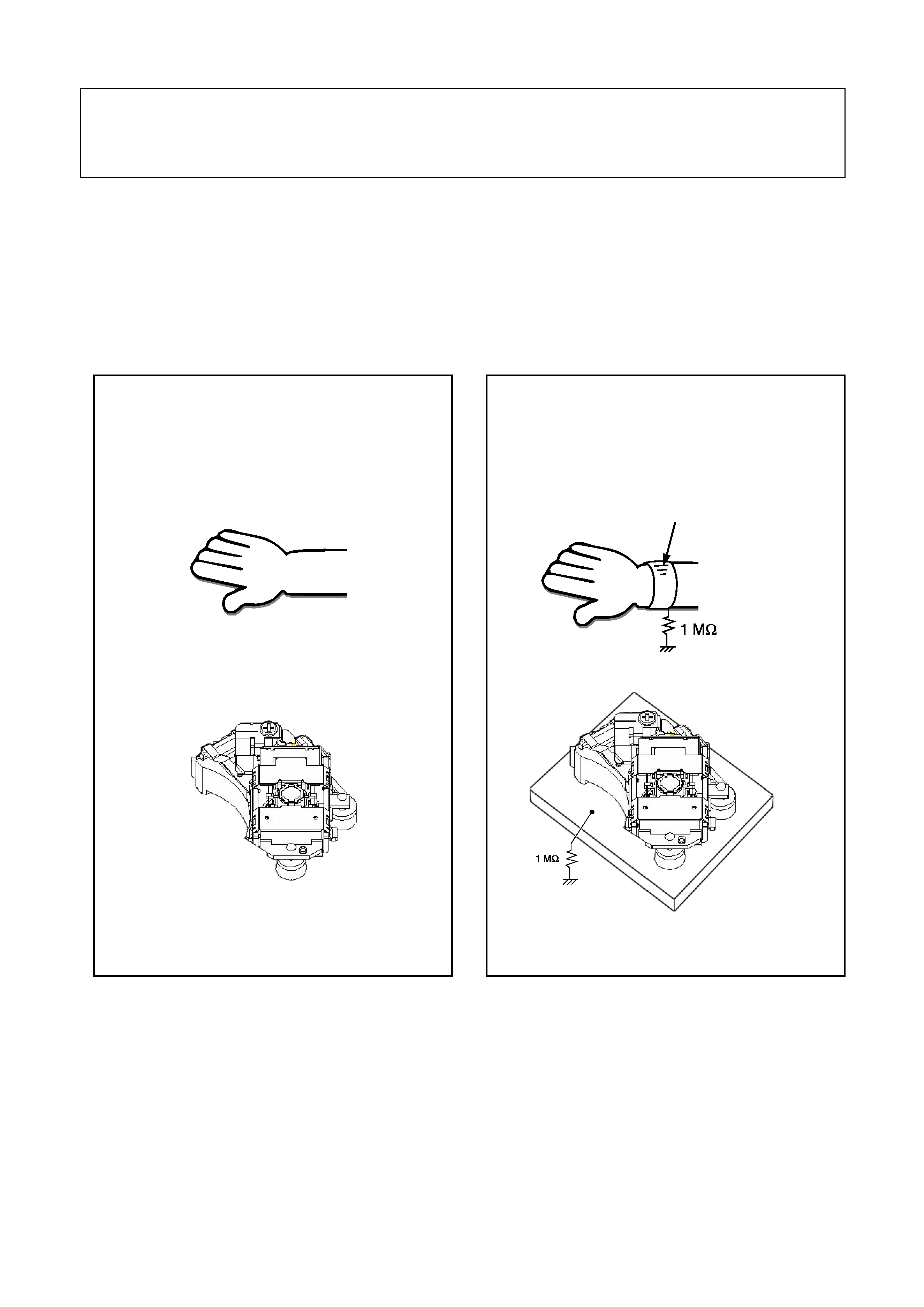
a. Human Body Grounding:
Many of the components used in this compact disc player, including the laser pickup, are sensitive to electrostatic
discharge.
Service personnel should be grounded with an electrostatic armband (1M ohm).
Caution: Static charge on clothing does not escape through a body grounding wristband. Be careful not to contact the
pickup or electrical components with your clothing.
b. Workbench and Tool Grounding:
A properly-grounded electroconductive plate (1 M ohm) or metal sheet should be fitted to the workbench surface.
Tools and instruments (soldering irons, scopes, etc.) should be grounded to prevent AC leakage.
c. Make two standard ESD solder bridges on the Laser optic PC Board
Before disassembly of mechanism or disconnect any cables in it, make two standard ESD solder bridges on the laser
optic PC Board.
Ground conductive wristband
for body
INCORRECT
CORRECT