PC board shown are viewed from parts side.
The parts with no reference number or no parts number
in the exploded views are not supplied.
As regards the resistors and capacitors, refer to the
circuit diagrams contained in this manual.
Parts marked with this sign are safety critical
components. they must be replaced with identical
ensure exact replacement.
!
components - refer to the appropriate parts list and
MICRO Hi-Fi SYSTEM
1 SPECIFICATIONS
3
2 ADJUSTMENT AND CHECKS
2
Parts of [ ] mark can be used only with the version designated.
TEAC
TEAC
MC-DX15/20
[E]: EUROPE [UK]: U.K. [AUS]: AUSTRALIA
[HK]: HONG KONG [SIN]: SINGAPORE
3 EXPLODED VIEW AND PARTS LIST
4 PC BOARDS AND PARTS LISTS
5 WIRING DIAGRAM
6 INCLUDED ACCESSORIES
11
19
21
6

1 SPECIFICATIONS
Amplifier Section
Output Power (L+R)
5W + 5W
Tuner Section (FM)
Frequency Range
87.5 MHz to 108.0 MHz
Input Sensitivity
300mV
Output Power Subwoofer: 15 W
Frequency Response :
50 to 20,000 Hz
Sensitivity (S/N30dB)
20dBuV
Tuner Section (AM)
Frequency Range
522 to 1620 kHz
Sensitivity (S/N20dB)
54dBuV/m
CD Player Section
Frequency Responce
20 to 20,000 Hz (+/-1dB)
Signa-to-Noise Ratio
55 dB
L & R speaker :
SPEAKER SYSTEM Section
Impedance :
Subwoofer:
4 ohms
Type :
Full range flat type
8 ohms
Wow and Flutter
Unmeasurable
Impedance :
Design and specifications are subject to change without notice.
Illustrations may differ slightly from production models.
Weight and dimensions are approximate.
MC-DX15/20
2
Power Requirements:
GENERAL
Dimension (W x H x D ):
Weight: (net)
Standard Accessories:
Main Unit
160 x 226 x 86 mm
Main Unit
0.96 kg
Power Consumption:
80 W
L & R Speaker 140 x 226 x 61mm
Speaker Cable x 2
Subwoofer
160 x 234 x 330mm
L & R Speaker 0.6 kg(each)
Subwoofer
5.3 kg
AM Antenna x 1
FM Antenna x 1
Battery for Remote Control x 1
Wall Mount Adaptor x 3
Remote Control Unit x 1
Wall Mount screw x 10
Subwoofer Cable x 1
Tape Plastic Wall Anchor x 10
Template for Wall Mounting x 1
Owner s Manual x 1
Warranty Card x 1
AC230V, 50 Hz
2 ADJUSTMENTS AND CHECKS
Use a screwdriver with a plastic or ceramic grip for all adjustment.
2-1 TUNER SECTION
1. Set the function switch to the AM position.
2. Connect the test loop antenna across the output of the signal generator.
3. Connect the oscilloscope to the speaker terminal.
4. Set the signal generator as listed in the alignment chart.
2-1-2 AM adjustment
1. Set the function switch to the FM position.
2. Connect the signal generator output through a 75 ohm dummy
3. Connect the oscilloscope to the speaker terminal.
4. Set the signal generator as listed in the alignment chart.
2-1-1 FM adjustment
antenna to "ANT" on MAIN PCB.
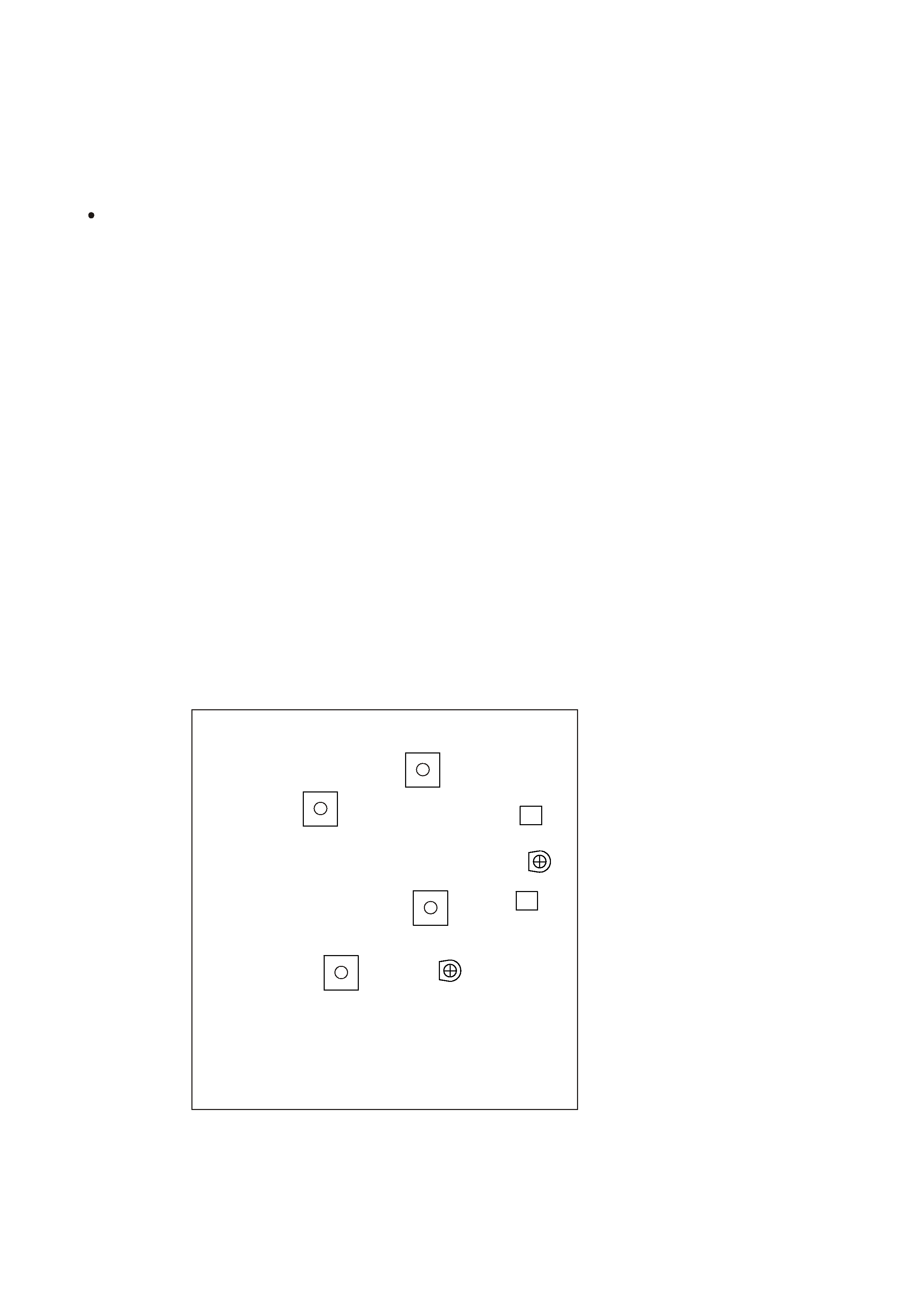
2-2 Adjustment and Test Points
3
MC-DX15/20 MAIN(TUNER) PCB
T205
L201
T204
SVC202
L202
SVC201
T203
T206
MC-DX15/20
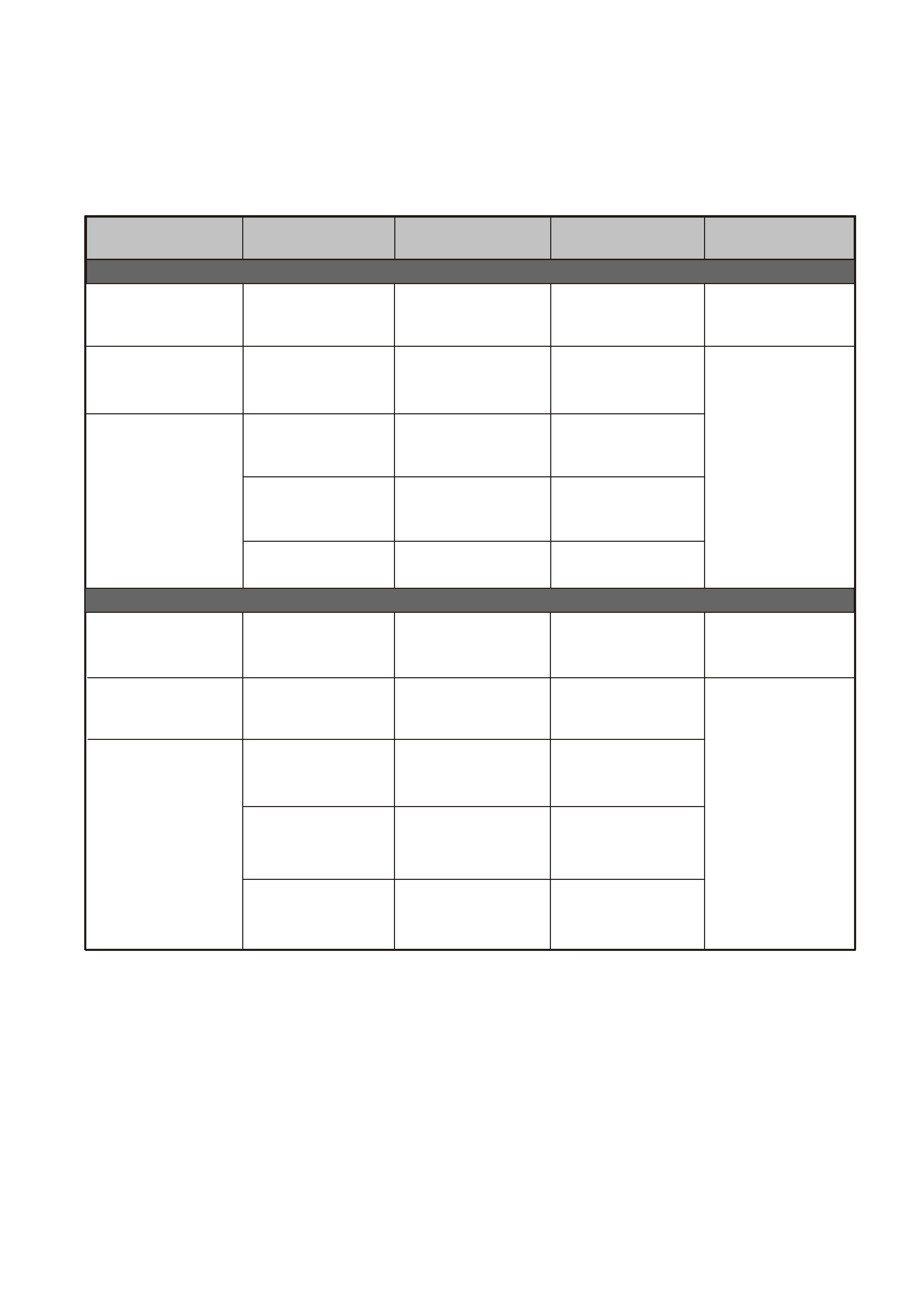
2-2-1 FM/AM alignment chart
ITEM
ADJUSTMENT POINT
ADJUSTMENT
SG SETTING
TUNER SETTING
2. FM band
3. Tracking
3. Tracking
106MHz
106MHz
Repeat step 3
87.5MHz
87.5MHz
1kHz, +/-22.5kHz dev.
1kHz, +/-22.5kHz dev.
L202
SVC201
FM
Adjust for max. output
and best waveform.
1. IF adjustment
2. AM band
455kHz
600kHz
1400kHz
1kHz, 30% mod
1kHz, 30% mod
1kHz, 30% mod
1kHz, 30% mod
T203
AM
Center for max. output.
Adjust for max. output
and best waveform.
2-3 CD SECTION
Auto alignment.
AM ant coil (T204)
522kHz
600kHz
1400kHz
1620kHz
90MHz
90MHz
1kHz, +/-22.5kHz dev.
L201
T206
Repeat step 3
SVC202
4
1.IFT adjustment
10.7 MHz
1kHz, +/-22.5kHz dev.
T205
108MHz
With 10.7 MHz at
zero crossover
522kHz
MC-DX15/20

2-4 Version s Differences
MC-DX15/20
,
MC-DX20
Version
Australia
AUS
SILVER
Color
AC Plug
MP3
75 OHM
Terminal
RDS
MC-DX15
AUS
NO
NO
Low Power
Consumption Standby
Circuit (Subwoofer)
NO
Australia
AUS
BLACK
AUS
YES
NO
NO
Europe
EUR
SILVER
VDE
YES
YES
YES
YES
UK
UK
SILVER
UK
YES
YES
YES
YES
Hong Kong
HK
SILVER
UK
YES
NO
YES
Singapore
SIN
SILVER
VDE
YES
NO
YES
5
YES
YES
YES
YES