D
D--7
70
0
SERVICE MANUAL
Multi D/A Converter
Effective : October, 2002
S-0077A
CONTENTS
1 SPECIFICATIONS
2
2 ADJUSTMENTS AND CHECKS
3
3 EXPLODED VIEWS AND PARTS LIST
5
4 PC BOARDS AND PARTS LIST
9
5 INCLUDED ACCESSORIES
17
NOTES
PC boards shown are viewed from parts side.
Parts marked with * require longer delivery time.
The parts with no reference number or no parts number in the
exploded views are not supplied.
As regards the resistors and capacitors, refer to the circuit diagrams
contained in this manual.
£
Parts marked with this sign are safety critical components. They
must be replaced with identical components - refer to the appropriate
parts list and ensure exact replacement.
Parts of [ ] mark can be used only with the version designated.
2
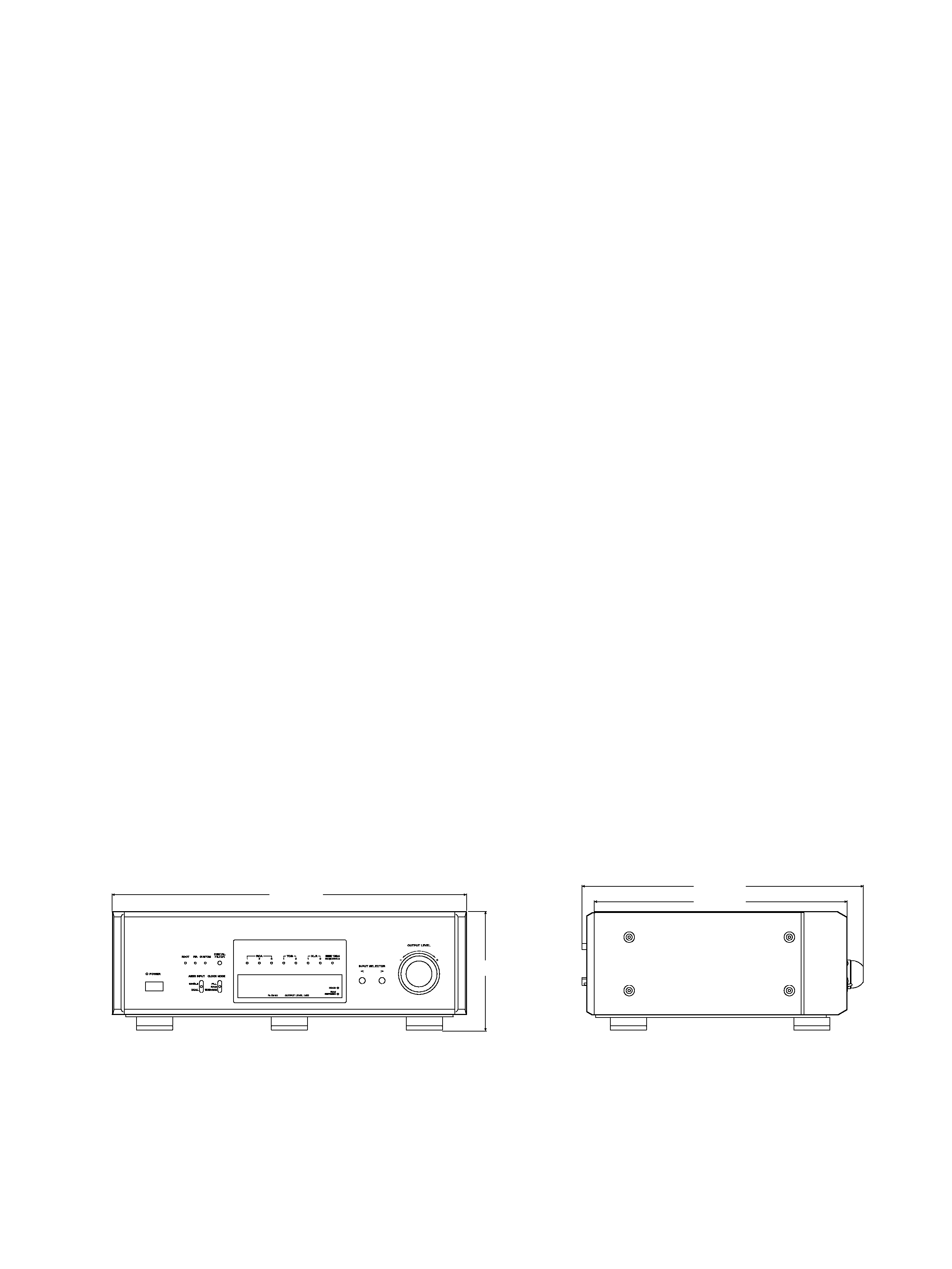
331mm
369mm
465mm
162mm
1 SPECIFICATIONS
Electrical characteristics (at 24bit/44.1kHz input)
Frequency response ........................................20Hz-20kHz ±0.3dB
S/N ratio ..............................................................................116dB
Dynamic range......................................................................108dB
THD ..................................................................................0.0025%
Channel separation ..............................................................115dB
Valid sampling frequencies (kHz)
32, 44.1, 48, 88.2, 96, 176.4, 192 (each ±1%)
Sampling frequencies (kHz) corresponding to de-emphasis
32, 44.1, 48
Input levels
TOS x 3 ........................24 to 14.5dBm peak (
:700nm typical)
SPDIF x 3 ........................................................0.5 Vp-p±0.1V/75
XLR x 2 ..........................................................5.0Vp-p±0.1V/110
Output levels
Analog outputs
RCA x 1 system............................................2.20Vrms±0.1V/47k
XLR x 1 system............................................2.20Vrms±0.1V/600
Digital output
TOS x 1............................................................-21 to -15dBm peak
WORD SYNC output
BNC x 2 ..........................................................................TTL / 75
General
Power supply ................................AC 230V, 50Hz (Europe model)
AC 120V, 60Hz (U.S.A./Canada model)
AC 220V, 60Hz (Korea model)
Power consumption ..............................................................26W
Dimensions (WxHxD) ..................................465 x 162 x 369 (mm)
Weight..........................................................................about 25 kg
Remote control unit
Type..............................................................Infrared pulse system
Battery ..........................................DC3V (AA batteries, SUM-3 x 2)
Dimensions (WxHxD) ....................................57 x 21 x 216 (mm)
Weight..........................................about 320g (including batteries)
Accessories
Power cord x 1
Remote Control Unit x 1
Batteries (AA, SUM-3) x 2
Felt x 3
Warranty card x 1
Owner's manual x 1
Improvements may result in specification or feature changes
without notice.
2-2 Audio System
Setting
CLOCK MODE: PLL
AES3 INPUT: SINGLE
DIGITAL FILTER: FIR
DIGITAL IN: Fs=44.1kHz, FullBit
If you intend to use a digital output of the P-70 or others for
connection to the digital input, use a digital signal that is not
upconverted.
2-2-1 DC Offset Adjustment
1. Set the OUTPUT SELECT switch on the rear panel to "XLR".
2. Apply a digital signal to the DIGITAL IN and check to see that
the input indicator turns on and that a sampling frequency
shows in the display. (Check of the lock status.)
3. Turn the OUTPUT LEVEL control counterclockwise, so that the
output level is
(as shown by "___._" in the display).
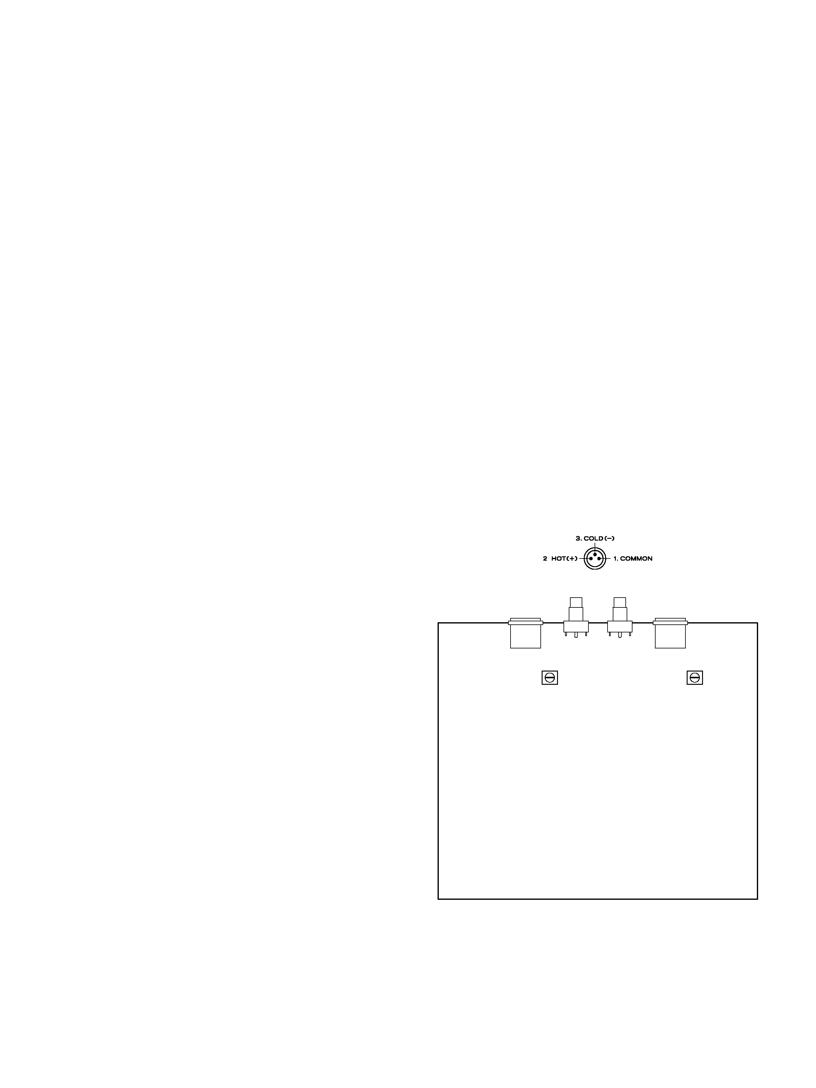
4. Measure the DC offset voltage between pins 2 (+) and 3 () of
LINE OUT (XLR). Adjust VR303 (L) and VR403 (R) on ANALOG
PCB for
5mV.
3
VR403
VR303
ANALOG PCB
2 ADJUSTMENTS AND CHECKS
2-1 Test Mode
2-1-1 Getting into Test Mode
While holding down the INPUT SELECTOR
and
buttons,
power on the unit and hit the DIGITAL FILTER button repeatedly.
2-1-2 Version Display
When the test mode is activated, the microcomputer version
information, "uComVer
X.XX
", is displayed. Then, at each
press of the INPUT SELECTOR
button, the RDOT version
information, "RDOTver
XXXX
", and the RAM version
information, "RAMversionXX", are displayed in sequence.
2-1-3 FL Grid Check
After displaying a series of version information, pressing the
INPUT SELECTOR
button activates the grid check mode and
the display reads "GridChecking". Turn the OUTPUT LEVEL
control to check to see that the grids turn off one after another.
Continue to turn the OUTPUT LEVEL control to check to see that
the grids turn on one after another.
2-1-4 FL Segment Check
When the FL grid check is done with, press the INPUT SELECTOR
button to activate the segment check mode. Turn the OUTPUT
LEVEL control to check to see that the dot matrix turns on by dot.
2-1-5 LED Check
When the FL segment check is done with, press the INPUT
SELECTOR
button to activate the LED check mode. The display
reads "LEDCHECK RDT". Turn the OUTPUT LEVEL control to
check to see that each LED turns on.
2-1-6 Resetting EEPROM
When the LED check is done with, press the INPUT SELECTOR
button and "! EEPRESET !" is displayed. Press the DIGITAL
FILTER button and the display changes to read "EEPSAVE
OK
" and the ROM is reset.
XLR pin assignments

4
2-2-2 Output level check
1. Connect the AC voltmeter to the LINE OUT.
2. Play the track 2 (1kHz, 0dB) of the MCD-111, and check the
output level.
Specifications: 2.2 0.2Vrms (100k load, RCA)
4.4 0.2Vrms (100k load, XLR)
2-2-3 Distortion check
1. Connect the distortion meter to the LINE OUT.
2. Play the track 2 (1kHz, 0dB) of the MCD-111, and check the
distortion.
Specification: 0.005% or less (400Hz HPF
20kHz LPF)
2-2-4 Frequency response check
1. Play the track 3-6 (20Hz 20kHz, 0dB) of the MCD-111, and
check that output level are within the specified values with
respect to the 1kHz reference level.
Specifications: 20Hz 20kHz, 0 1dB (FIR mode)
20Hz 20kHz, 0 1dB (CUSTOM mode)
20kHz, 3 1dB (RDOT mode)
The DIGITAL FILTER button cycles through the following
modes:
2-2-5 S/N check
1. Play the track 7 (non-signal) of the MCD-111, and check that
noise level are within the specified values with respect to the
1kHz reference level.
Specification: 100dB or more (IEC-A)
2-2-6 Channel separation check
1. Play the track 8 (L:1kHz / R:non-signal) of the MCD-111, and
check the leakage from Lch to Rch.
2. In the same way, play the track 10 (R:1kHz / L:non-signal) of
the MCD-111, and check the leakage from Rch to Lch.
Specification: 100dB or more (IEC-A)
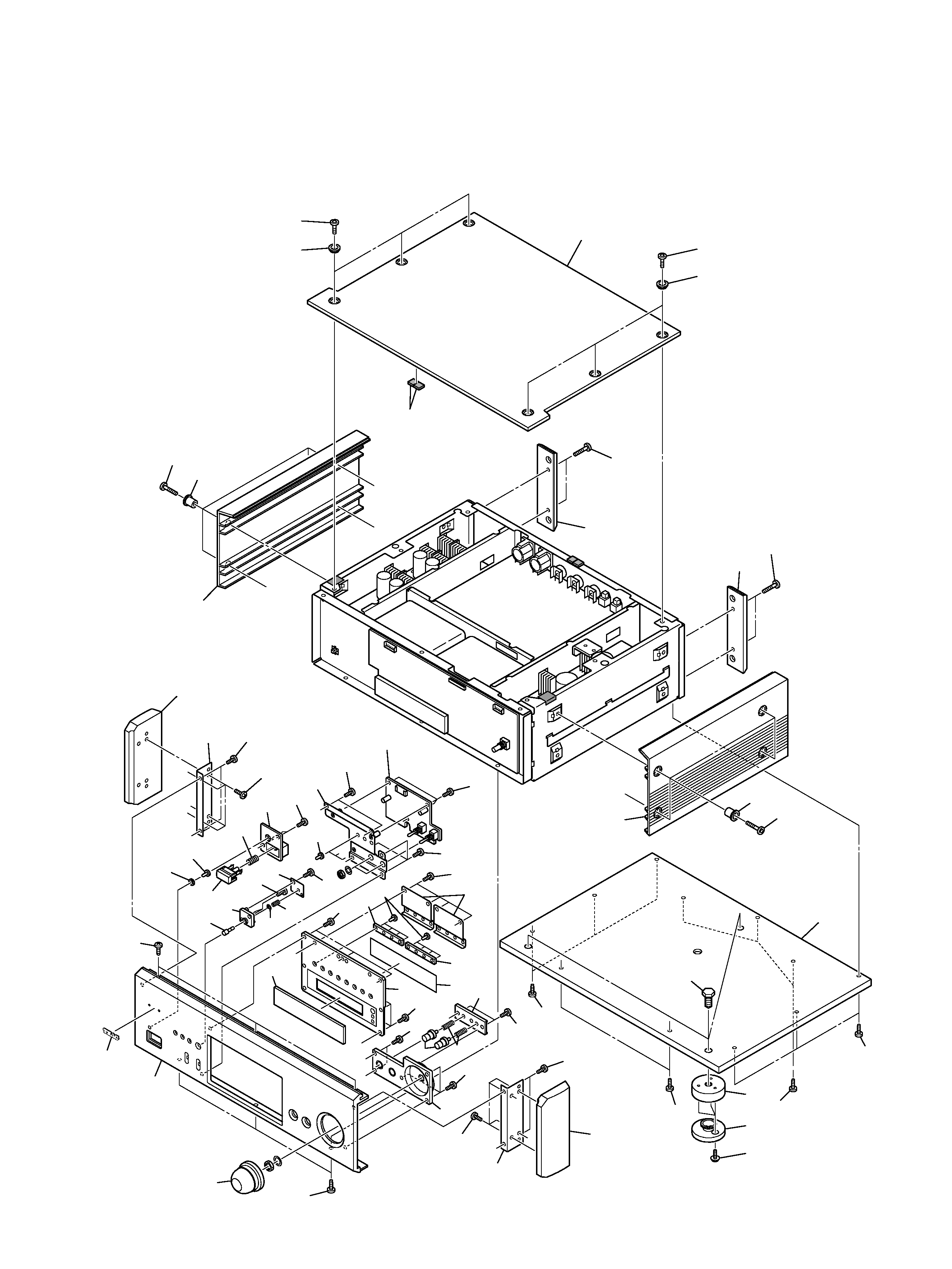
EXPLODED VIEW-1
5
1
2
3
4
5
6
6
7
7
8
8
9
0
q
q
q
w
w
e
r
t
y
u
i
o
p
a
s
s
d
f
g
h
j
k
l
;
2
z
c
!
!
@
@
@
#
#
#
#
#
#
#
$
$
%
%
%
^
^
&
*
*
(
(
Q
Q
Q
Q
3
@
v
b
x
)
3 EXPLODED VIEWS AND PARTS LIST