A
A--LL770
00
0P
P
SERVICE MANUAL
Power Amplifier
Effective : January, 2003
S-0084A
NOTES
PC boards shown are viewed from parts side.
The parts with no reference number or no parts number in the
exploded views are not supplied.
As regards the resistors and capacitors, refer to the circuit diagrams
contained in this manual.
£
Parts marked with this sign are safety critical components. They
must be replaced with identical components - refer to the appropriate
parts list and ensure exact replacement.
Parts of [ ] mark can be used only with the version designated.
CONTENTS
1 SPECIFICATIONS
2
2 ADJUSTMENTS
2
3 EXPLODED VIEWS AND PARTS LIST
3
4 PC BOARDS AND PARTS LIST
5
1 SPECIFICATIONS
2
Power outputs .................................. 30 W/ch (6 , 0.5 %, 1 kHz)
Input sensitivity ............................................................ 1 V/47 k
Frequency response ...................... 20 Hz to 20,000 Hz (+1/-3 dB)
Power requirements .................. AC 230 V, 50 Hz (Europe model)
AC 120 V, 60 Hz (U.S.A./Canada model)
Power consumption.................................. 45 W (STANDBY : 5 W)
Dimensions (WxHxD).................................... 215 x 109 x 339 mm
Weight.................................................................................. 2.5 kg
Operating temperature ................................................ 5 °C ~ 40 °C
Operating humidity...................................................... 5 % ~ 90 %
Storage temperature ................................................ -20 °C ~ 55 °C
Accessories .......................................... RCA cable (red/white) x 1
RCA cable (black) x 1
LINK cable x 1
· Design and specifications are subject to change without notice.
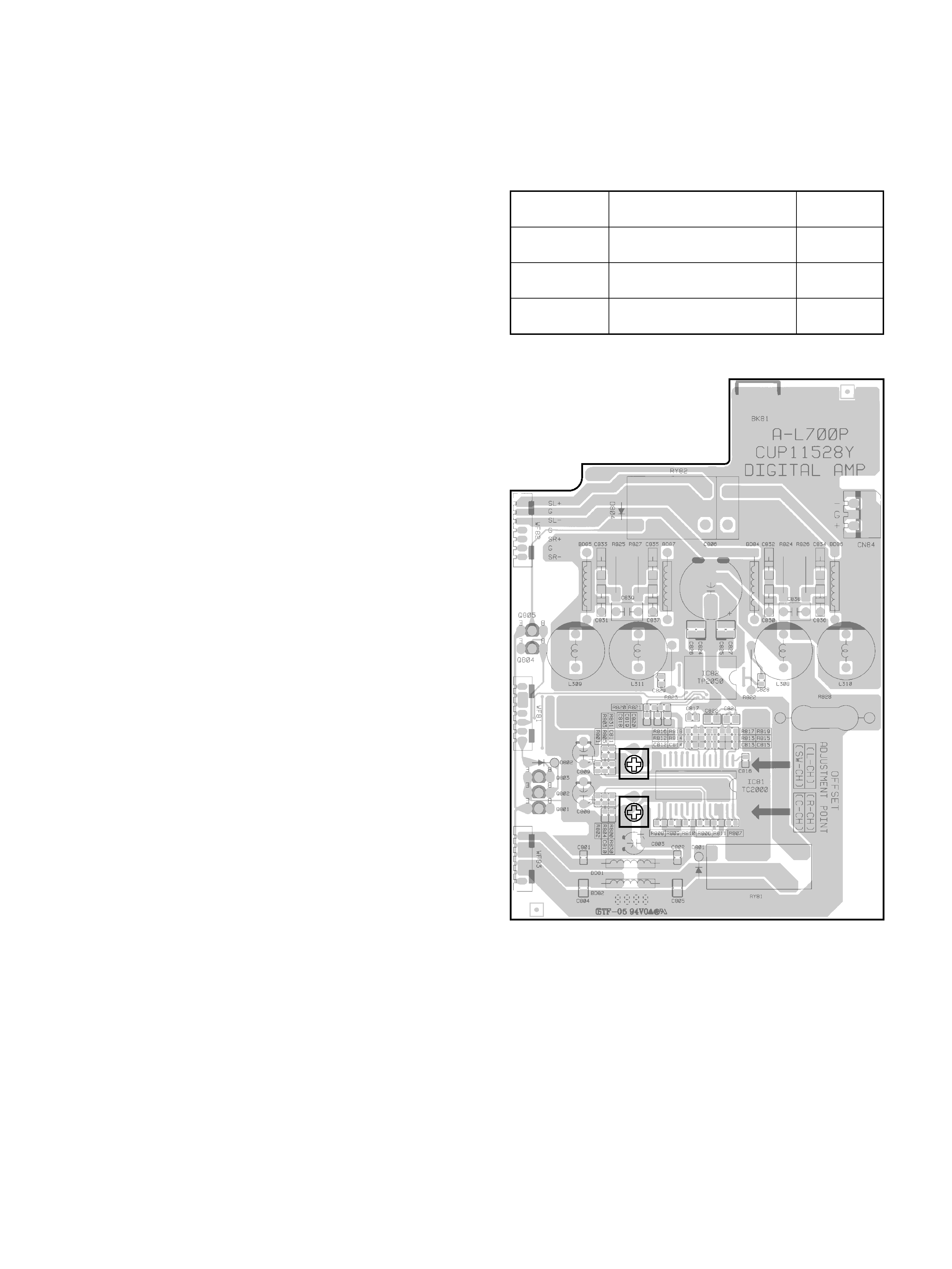
2 ADJUSTMENTS
DC Offset Level Adjustment
DC Voltmeter...............Connect to speaker output terminal
VR81
VR80
SURROUND (L)
SURROUND (R)
CENTER
DC Voltmeter 0V (-30mV~+30mV)
VR81
VR80
VR80
ADJUST FOR
ADJUSTMENT
CHANNEL
DC Voltmeter 0V (-30mV~+30mV)
DC Voltmeter 0V (-30mV~+30mV)
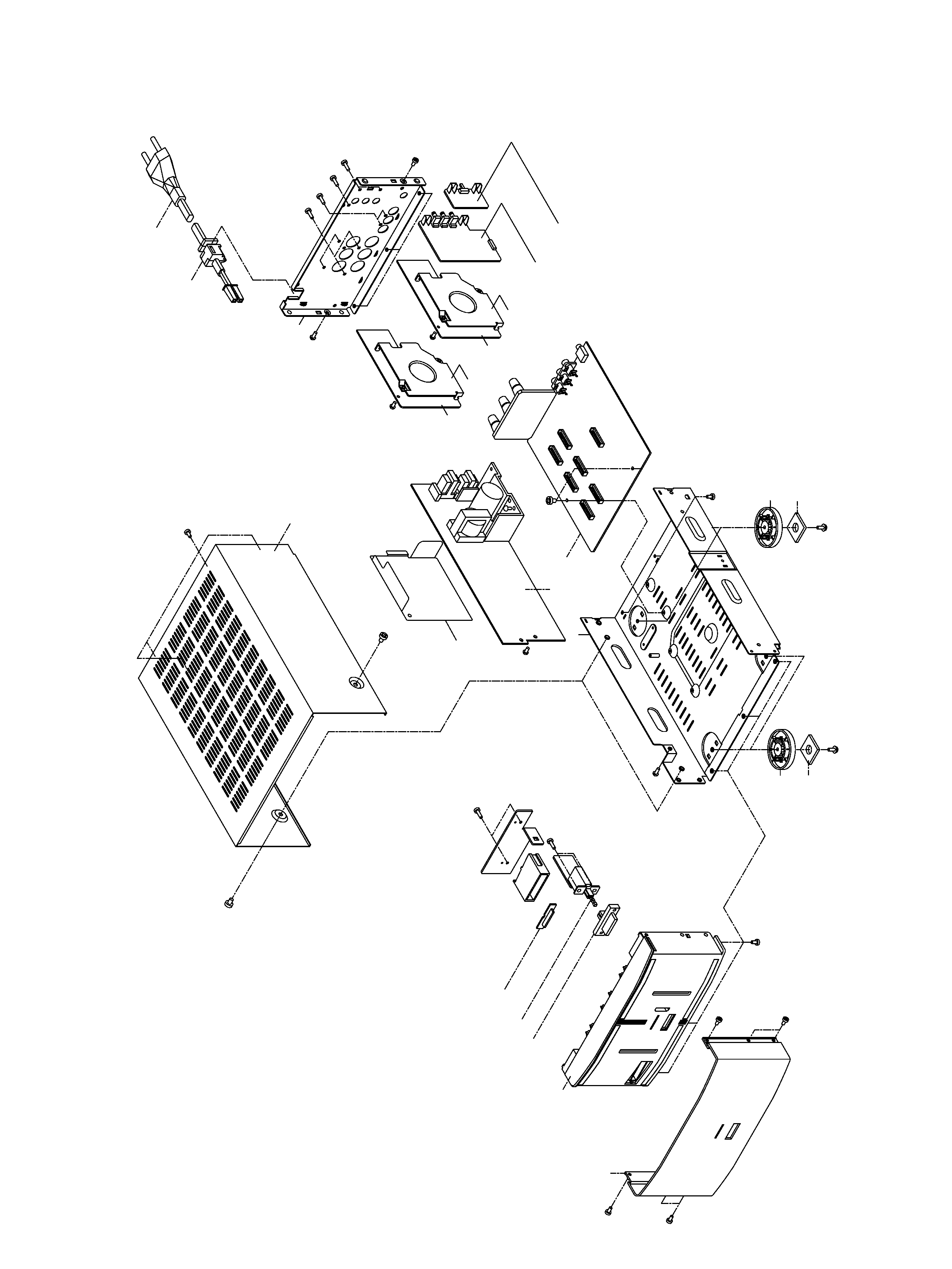
3 EXPLODED VIEWS AND PARTS LIST
3
2
3
4
5
1
8
9
0
q
w
7
r
t
y
u
i
e
p
a
o
t
8
7

4
EXPLODED VIEW LIST
£
£
£
£
£
INCLUDED ACCESSORIES
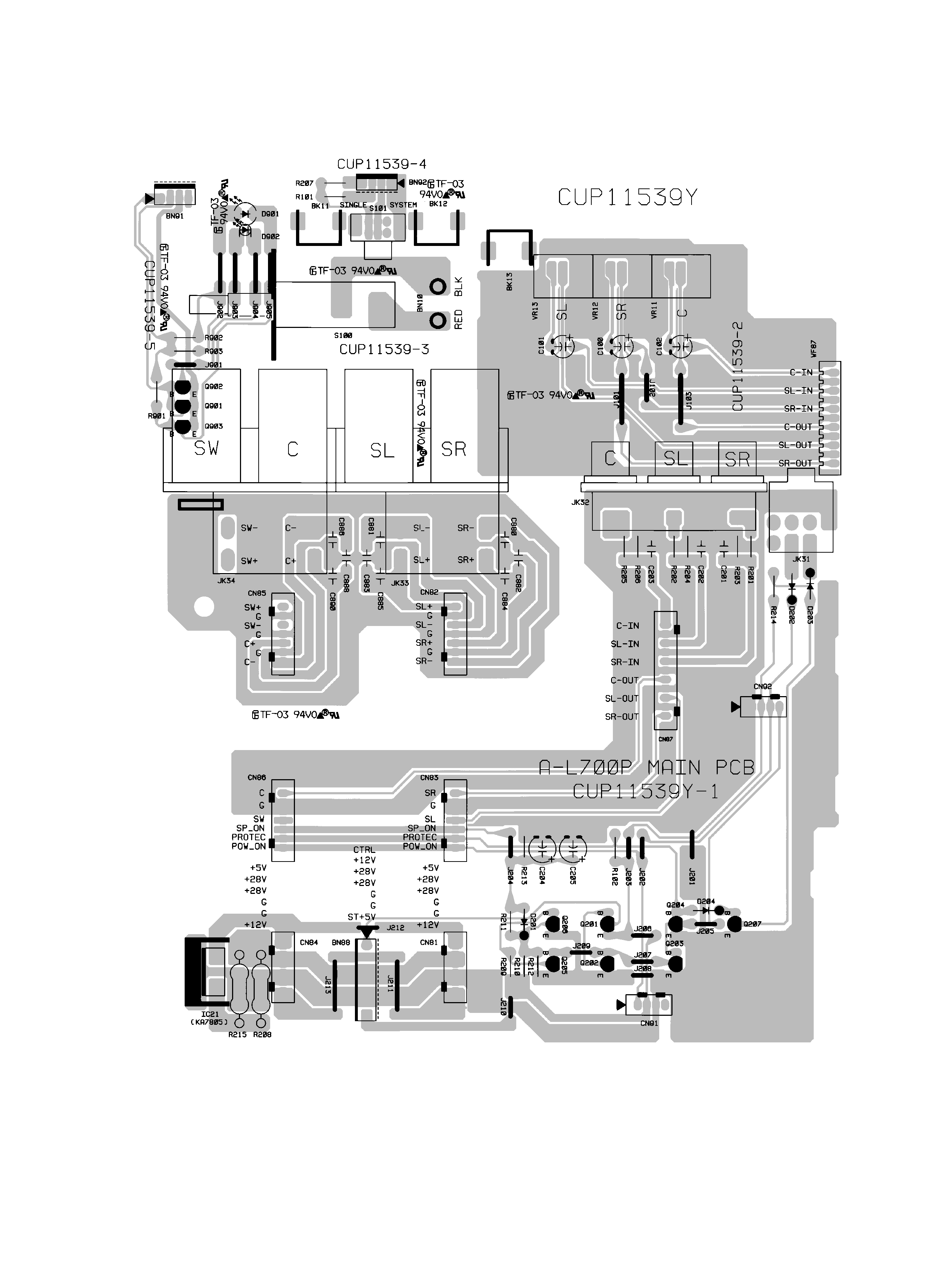
4 PC BOARDS AND PARTS LIST
5
MAIN PCB (GATHER)