a-h500
`
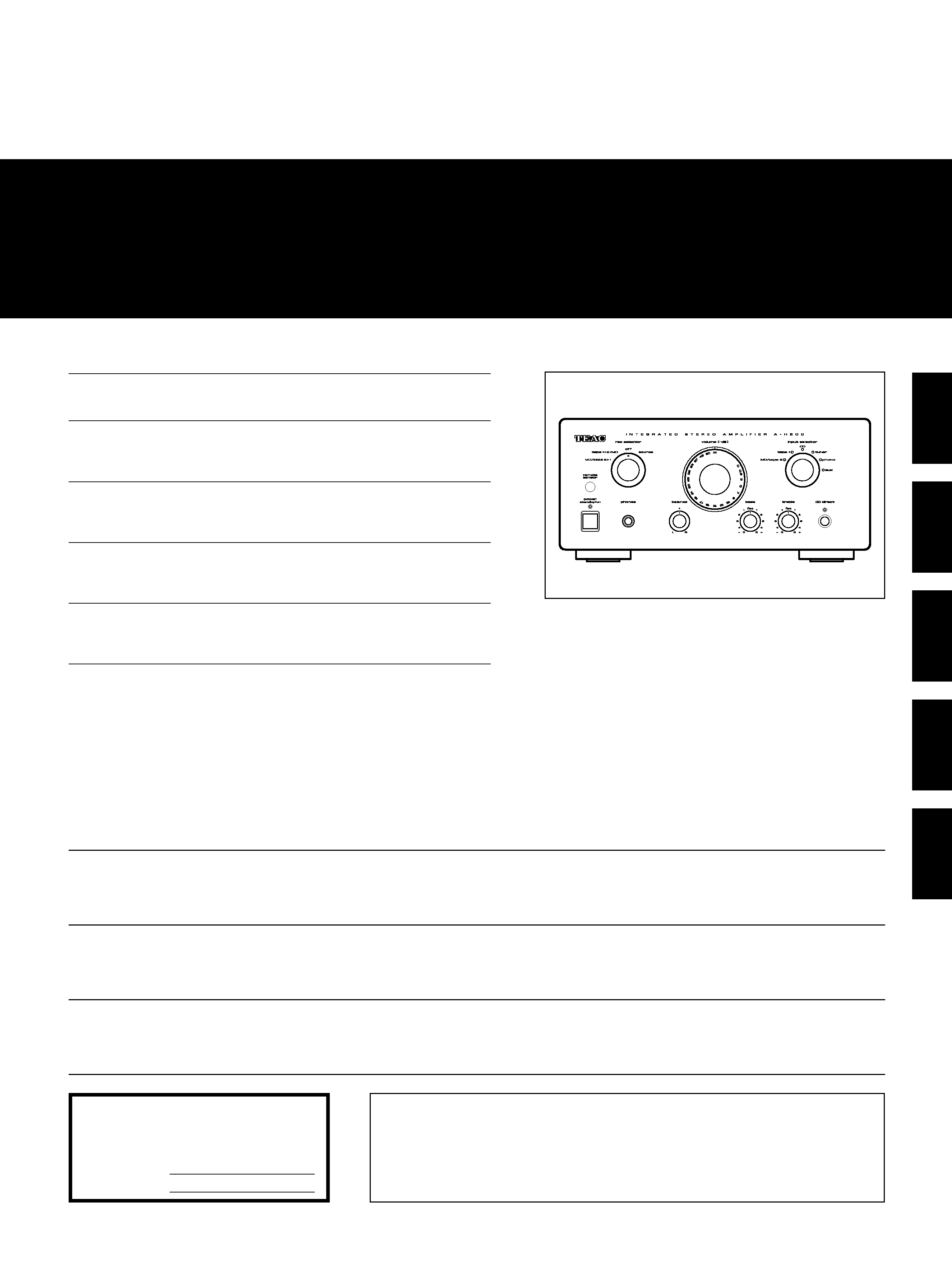
INTEGRATED STEREO AMPLIFIER
9A06054500
This appliance has a serial number located
on the rear panel. Please record the model
number and serial number and retain them
for your records.
Model number
Serial number
WARNING: TO PREVENT FIRE OR SHOCK
HAZARD, DO NOT EXPOSE THIS
APPLIANCE TO RAIN OR MOISTURE.
The exclamation point within an equilateral triangle is intended to alert the user to the
presence of important operating and maintenance (servicing) instructions in the literature
accompanying the appliance.
The lightning flash with arrowhead symbol, within equilateral triangle, is intended to alert
the user to the presence of uninsulated "dangerous voltage" within the product's enclosure
that may be of sufficient magnitude to constitute a risk of electric shock to persons.
CAUTION: TO REDUCE THE RISK OF ELECTRIC SHOCK, DO NOT
REMOVE COVER (OR BACK). NO USER-SERVICEABLE PARTS INSIDE.
REFER SERVICING TO QUALIFIED SERVICE PERSONNEL.
Ü
ÿ
Y
Thanks for buying a TEAC. Read this manual carefully to get the
best performance from this unit.
Nous vous remercions pour l'achat d'un appareil TEAC.
Lire ce manuel avec attention pour obtenir les meilleures
performances possibles de cet appareil.
Vielen Dank für den Kauf dieses TEAC-Geräts.
Bitte lesen Sie diese Anleitung sorgfältig durch, um die Leistungs-
fähigkeit dieses Geräts optimal nutzen zu können.
Grazie per aver acquistato un prodotto TEAC.
Leggere attentamente questo manuale per ottenere le migliori
prestazioni da questo apparecchio.
Enhorabuena por la adquisición de un TEAC.
Lea detenidamente este manual a fin de obtener el mejor
rendimiento de esta unidad.
OWNER'S MANUAL .................... 3
MANUEL DU PROPRIETAIRE ...... 11
BEDIENUNGSANLEITUNG........... 19
MANUALE DI ISTRUZIONI .......... 27
MANUAL DEL USUARIO ............. 35
ENGLISH
FRANÇAIS
DEUTSCH
IT
ALIANO
ESP
AÑOL
Important Safety Instructions
_ 2 _
CAUTION:
·· Read all of these Instructions.
·· Save these Instructions for later use.
·· Follow all Warnings and Instructions marked on the audio
equipment.
1) Read Instructions -- All the safety and operating instructions
should be read before the product is operated.
2) Retain Instructions -- The safety and operating instructions
should be retained for future reference.
3) Heed Warnings -- All warnings on the product and in the
operating instructions should be adhered to.
4) Follow Instructions -- All operating and use instructions should
be followed.
5) Cleaning -- Unplug this product from the wall outlet before
cleaning. Do not use liquid cleaners or aerosol cleaners. Use a
damp cloth for cleaning.
6) Attachments -- Do not use attachments not recommended by
the product manufacturer as they may cause hazards.
7) Water and Moisture -- Do not use this product near water _ for
example, near a bath tub, wash bowl, kitchen sink, or laundry tub; in
a wet basement; or near a swimming pool; and the like.
8) Accessories -- Do not place this product on an unstable cart,
stand, tripod, bracket, or table. The product may fall, causing serious
injury to a child or adult, and serious damage to the product. Use
only with a cart, stand, tripod, bracket, or table recommended by the
manufacturer, or sold with the product. Any mounting of the product
should follow the manufacturer's instructions, and should use a
mounting accessory recommended by the manufacturer.
9) A product and cart combination should be moved with care.
Quick stops, excessive force, and uneven surfaces may cause the
product and cart combination to overturn.
10) Ventilation -- Slots and openings in the cabinet are provided
for ventilation and to ensure reliable operation of the product and to
protect it from overheating, and these openings must not be
blocked or covered. The openings should never be blocked by
placing the product on a bed, sofa, rug, or other similar surface.
This product should not be placed in a built-in installation such as a
bookcase or rack unless proper ventilation is provided or the
manufacturer's instructions have been adhered to.
11) Power Sources -- This product should be operated only from
the type of power source indicated on the marking label. If you are
not sure of the type of power supply to your home, consult your
product dealer or local power company. For products intended to
operate from battery power, or other sources, refer to the operating
instructions.
12) Grounding or Polarization -- This product may be equipped
with a polarized alternating-current line plug (a plug having one
blade wider than the other). This plug will fit into the power outlet
only one way. This is a safety feature. If you are unable to insert the
plug fully into the outlet, try reversing the plug. If the plug should still
fail to fit, contact your electrician to replace your obsolete outlet. Do
not defeat the safety purpose of the polarized plug.
13) Power-Cord Protection -- Power-supply cords should be
routed so that they are not likely to be walked on or pinched by
items placed upon or against them, paying particular attention to
cords at plugs, convenience receptacles, and the point where they
exit from the product.
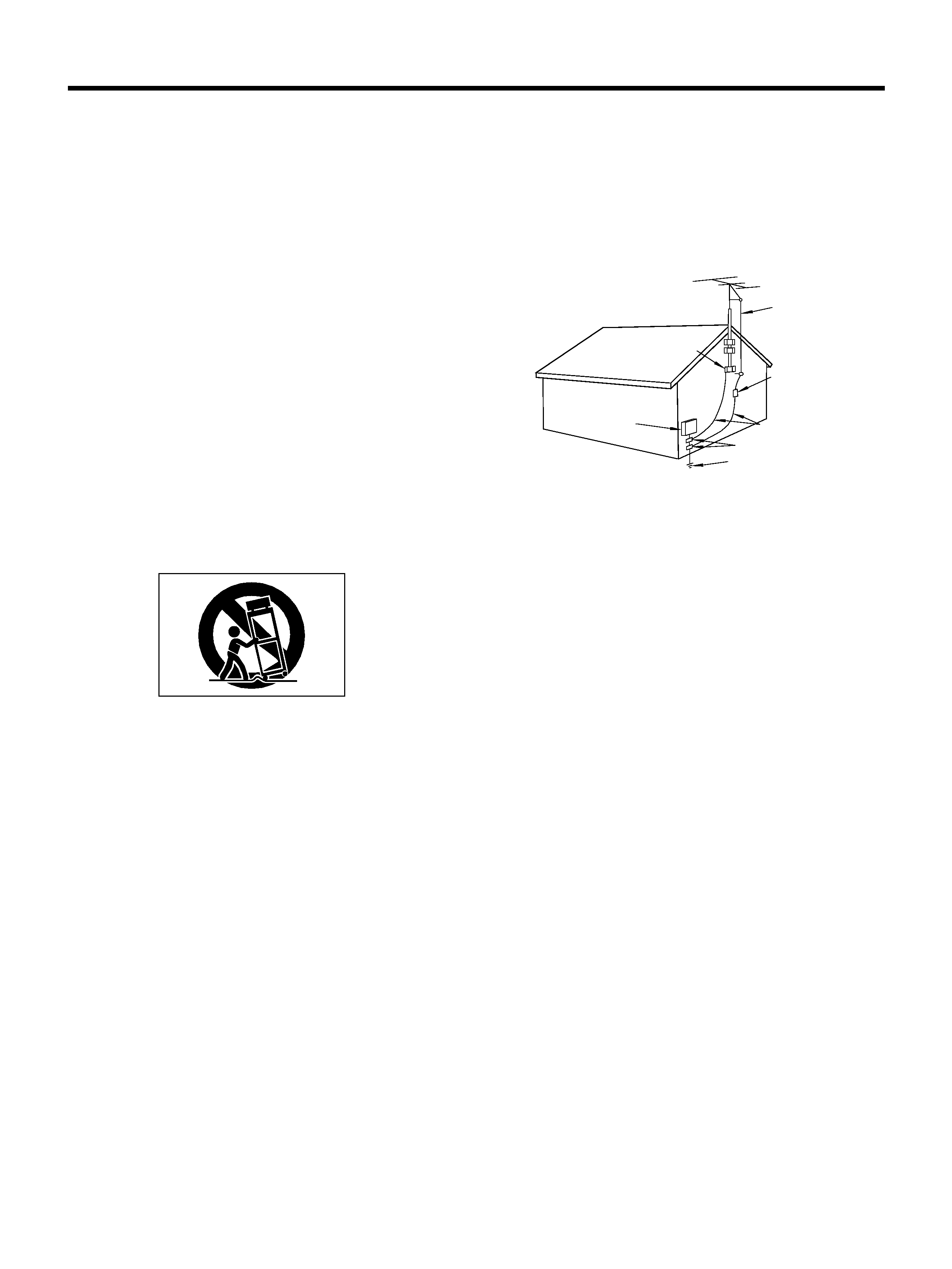
14) Outdoor Antenna Grounding -- If an outside antenna or
cable system is connected to the product, be sure the antenna or
cable system is grounded so as to provide some protection against
voltage surges and built-up static charges. Article 810 of the
National Electrical Code, ANSI/NFPA 70, provides information with
regard to proper grounding of the mast and supporting structure,
grounding of the lead-in wire to an antenna discharge unit, size of
grounding conductors, location of antenna-discharge unit,
connection to grounding electrodes, and requirements for the
grounding electrode.
"Note to CATV system installer:
This reminder is provided to call the CATV system installer's
attention to Section 820-40 of the NEC which provides guidelines
for proper grounding and, in particular, specifies that the cable
ground shall be connected to the grounding system of the building,
as close to the point of cable entry as practical.
ANTENNA
LEAD IN
WIRE
ANTENNA
DISCHARGE UNIT
(NEC SECTION 810-20)
G
ROUNDING CONDUCTORS
(NEC SECTION 810-21)
GROUND CLAMPS
POWER SERVICE GROUNDING
ELECTRODE SYSTEM
(NEC ART 250. PART H)
NEC - NATIONAL ELECTRICAL CODE
ELECTRIC
SERVICE
EQUIPMENT
Example of Antenna Grounding as per
National Electrical Code, ANSI/NFPA 70
GROUND
CLAMP
15) Lightning -- For added protection for this product during a
lightning storm, or when it is left unattended and unused for long
periods of time, unplug it from the wall outlet and disconnect the
antenna or cable system. This will prevent damage to the product
due to lightning and power-line surges.
16) Power Lines -- An outside antenna system should not be
located in the vicinity of overhead power lines or other electric light
or power circuits, or where it can fall into such power lines or
circuits. When installing an outside antenna system, extreme care
should be taken to keep from touching such power lines or circuits
as contact with them might be fatal.
17) Overloading -- Do not overload wall outlets, extension cords,
or integral convenience receptacles as this can result in risk of fire
or electric shock.
18) Object and Liquid Entry -- Never push objects of any kind into
this product through openings as they may touch dangerous voltage
points or short-out parts that could result in a fire or electric shock.
Never spill liquid of any kind on the product.
19) Servicing -- Do not attempt to service this product yourself as
opening or removing covers may expose you to dangerous voltage
or other hazards. Refer all servicing to qualified service personnel.
20) Damage Requiring Service -- Unplug this product from the
wall outlet and refer servicing to qualified service personnel under
the following conditions:
a) when the power-supply cord or plug is damaged.
b) if liquid has been spilled, or objects have fallen into the product.
c) if the product has been exposed to rain or water.
d) if the product does not operate normally by following the
operating instructions. Adjust only those controls that are covered
by the operating instructions as an improper adjustment of other
controls may result in damage and will often require extensive work
by a qualified technician to restore the product to its normal
operation.
e) if the product has been dropped or damaged in any way.
f ) when the product exhibits a distinct change in performance _
this indicates a need for service.
21) Replacement Parts -- When replacement parts are required,
be sure the ser vice technician has used replacement par ts
specified by the manufacturer or have the same characteristics as
the original part. Unauthorized substitutions may result in fire,
electric shock, or other hazards.
22) Safety Check -- Upon completion of any service or repairs to
this product, ask the service technician to perform safety checks to
determine that the product is in proper operating condition.
23) Wall or Ceiling Mounting -- The product should be mounted
to a wall or ceiling only as recommended by the manufacturer.
24) Heat -- The product should be situated away from heat sources
such as radiators, heat registers, stoves, or other products
(including amplifiers) that produce heat.

ENGLISH
Before Use
_ 3 _
OPlace the amplifier on a hard flat
surface.
OThe ventilation holes should not be
covered. Make sure there is at least 20
cm (8 inches) of space above and at
least 5 cm (2 inches) of space besides
the amplefier. Do not place CD player or
other equipment on top of the amplifier.
OAvoid placing it in direct sunlight or
close to a source of heat. Also avoid
locations subject to vibrations and
excessive dust, heat, cold or moisture.
ODo not open the cabinet, as this might
result in circuitry damage or electrical
shock.
ODo not attempt to clean the unit with
chemical solvents as this might damage
the finish. Use a clean, dry cloth.
Table of Contents
Connection..................................................... 4
Rear Panel Overview.................................... 5
Speaker Connection..................................... 5
Front Panel Controls and Their
Functions..................................................... 6
Basic Operation ............................................ 7
Recording....................................................... 7
Remote Control Operation........................... 8
AI Direct Play Function ................................ 9
Specifications................................................ 9
Troubleshooting .......................................... 10
Read This Before Operating
IMPORTANT (for U.K. Customers)
DO NOT cut off the mains plug from this
equipment. If the plug fitted is not
suitable for the power points in your
home or the cable is too short to reach
a power point, then obtain an
appropriate safety approved extension
lead or consult your dealer.
If nonetheless the mains plug is cut off,
remove the fuse and dispose of the plug
immediately, to avoid a possible shock
hazard by inadvertent connection to the
mains supply.
If this product is not provided with a
mains plug, or one has to be fitted, then
follow the instructions given below:
IMPORTANT. DO NOT make any
connection to the larger terminal which
is marked with the letter E or by the
safety earth symbo
ç or coloured
GREEN or GREEN-and-YELLOW.
The wires in the mains lead on this
product are coloured in accordance
with the following code:
BLUE:
NEUTRAL
BROWN:
LIVE
As these colours may not correspond
with the coloured markings identifying
the terminals in your plug proceed as
follows:
The wire which is coloured BLUE must
be connected to the terminal which is
marked with the letter N or coloured
BLACK.
The wire which is coloured BROWN
must be connected to the terminal
which is marked with the letter L or
coloured RED.
When replacing the fuse only a
correctly rated approved type should
be used and be sure to re-fit the fuse
cover.
IF
IN
DOUBT
--
CONSULT
A
COMPETENT ELECTRICIAN.
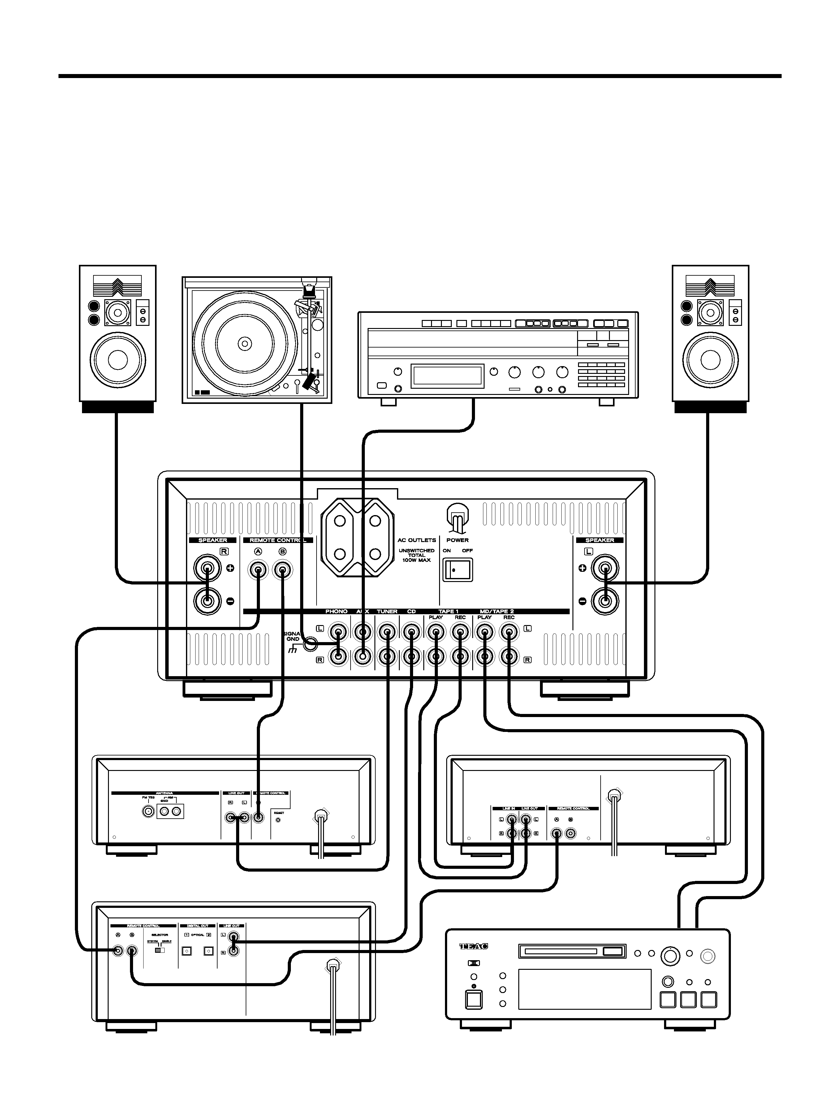
Connection
_ 4 _
Speaker placement
The playback characteristics of the
speakers are greatly influenced by the
placement and the room in which the
speakers are used. To find the best
location for the speakers play back some
music without using the tone controls and
move the speakers around. However,
please keep the following in mind:
ODo not use this unit with it housed in a
box or the like including an audio rack.
To prevent damage to the speakers:
ODo not raise the volume level
excessively.
OTurn off the amplifier when connecting
or disconnecting.
ODo not touch the speaker's diaphragms.
OPlace the speakers on a flat, solid
surface which is free from vibrations.
OPlace the speakers in an area that is
well ventilated. Do not place the
speakers in a humid place.
OKeep the speakers away from direct
sunlight and heat sources (stoves, etc.).
OKeep the speakers away from the
turntable.
Record Player (turntable)
AMPLIFIER (A-H500)
TUNER (T-H500)
CASSETTE DECK (R-H500)
MD Player or Second Cassette Deck
CD Player (PD-H500)
VCR or auxiliary source unit
OUTPUT
INPUT
ENGLISH
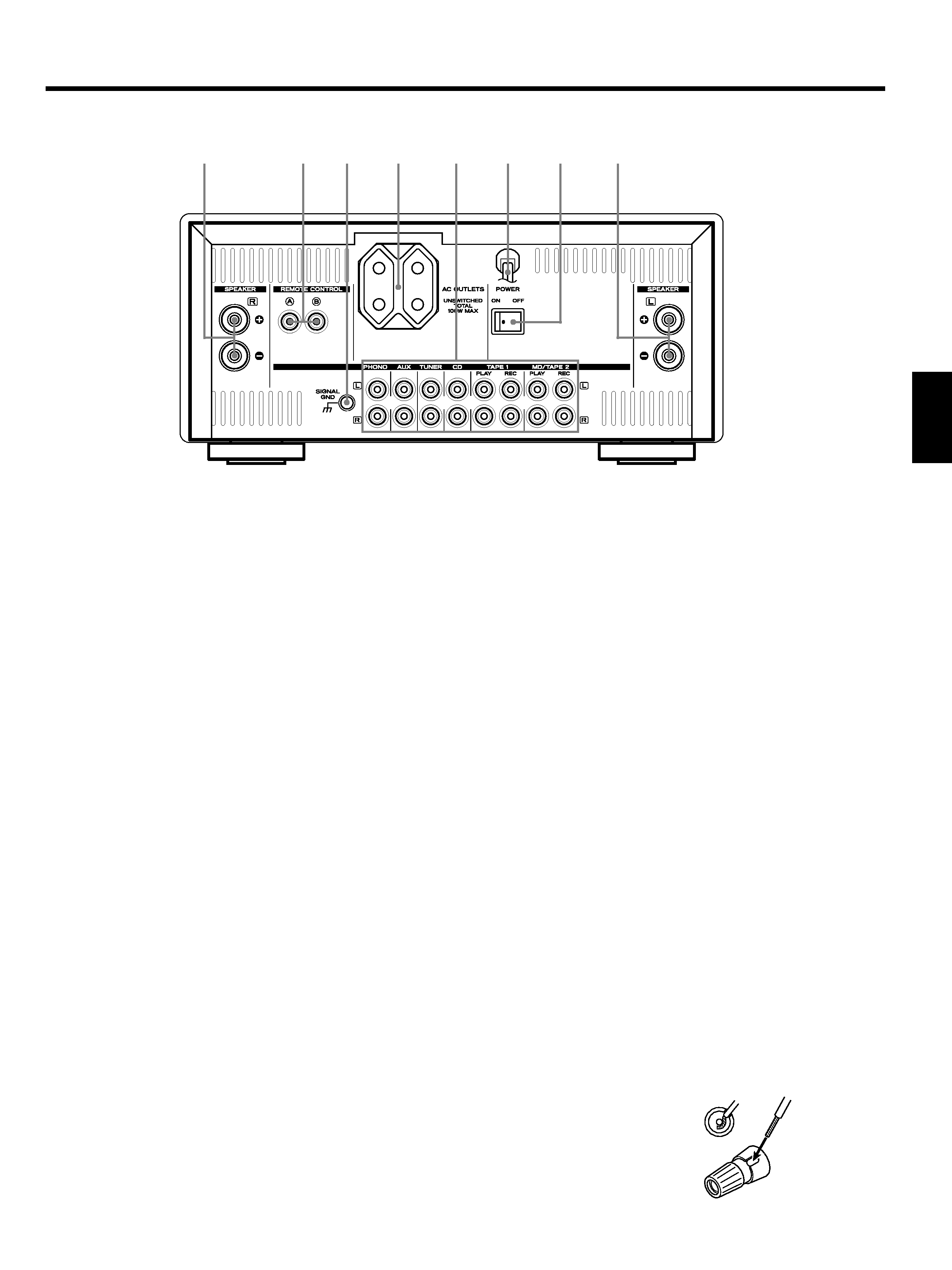
Rear Panel Overview
_ 5 _
1Right speaker terminals
2Remote control jacks
These jacks are used for the connection of
the TEAC Mini component system (T-H500,
R-H500, PD-H500) for the purpose of
operating it using the Remote Control unit
(RC-613 provided with the A-H500
amplifier) or system control signals.
3Signal ground terminal
Connect the ground lead of the record
player (turntable) to this terminal.
4AC OUTLETS (unswitched)
Plug the AC power cord of the source unit
(CD player, cassette deck, etc.) into this AC
OUTLETS.
5Audio signal jacks:
O MD/TAPE 2 PLAY/REC jacks
These jacks are used for the connection
of the MD player or the second cassette
deck.
Connect the output (LINE OUT) jacks of
the MD player or cassette deck to the
PLAY jacks; the input (LINE IN) jacks of
the MD player or cassette deck to the
REC jacks.
O TAPE 1 PLAY/REC jacks
Connec the output (LINE OUT) jacks of
the cassette deck (R-H500) to the PLAY
jacks; the input (LINE IN) jacks of the
cassette deck to the REC jacks
.
O CD input jacks
Connec the output (LINE OUT) jacks of
the CD player (PD-H500) to these jacks.
O TUNER input jacks
Connect the output (LINE OUT) jacks of
the tuner (T-H500) to these jacks.
O AUX input jacks
Connec the output jacks of the VCR or
other AUXiliary source unit to these
jacks.
O PHONO input jacks
Connect the output jacks of the record
player (turntable) to these jacks.
Note:
Make sure that you connect the white
pin-plug to the white jacks (left); red
pin-plug to the red jacks (right).
6AC power cord
Plug this AC power cord into an AC wall
socket.
7Main power switch
Press the ON side of this rocker (seesaw)
switch to turn the power ON (standby
position); press the OFF side to turn the
power off.
Note:
Leave this main power switch ON at all
times.
8Left speaker terminals
Speaker Connection
Before connecting
OCheck the impedance of your speakers.
Connect speaker with an impedance of 4
to 16 ohms.
The amplifier's red speaker terminals
are the (positive) terminals and the
black terminals are the (negative)
terminals.
OThe side of the speaker cable is
marked to make it distinguishable from
the side of the cable. Connect this
marked side to the red terminal and
the unmarked side to the black terminal.
OPrepare
the
speaker
cords
for
connection
by
stripping
off
approximately 1 cm or less (no more as
this could cause a short-circuit) of the
outer insulation.
How to connect
(1) Twist the wires tightly together so that
they are not straggly.
(2) Turn the terminal cap counterclockwise
to loosen it.
The speaker termianl caps cannot be
fully removed from the base.
(3) Insert the wire into the terminal fully
and turn the terminal cap clockwise to
securely connect it.
(4) Make sure it is fastened firm by pulling
the cord lightly.
45
6
7
8
12
3