A
A--HH330000m
mkk##
SERVICE MANUAL
Integrated Stereo Amplifier
Effective : July, 2004
S-0120A
CONTENTS
1 SPECIFICATIONS
2
2 IC PIN FUNCTIONS
3
3 EXPLODED VIEWS AND PARTS LIST
4
4 PC BOARDS AND PARTS LIST
6
NOTES
PC boards shown are viewed from parts side.
The parts with no reference number or no parts number in the
exploded views are not supplied.
As regards the resistors and capacitors, refer to the circuit diagrams
contained in this manual.
£
Parts marked with this sign are safety critical components. They
must be replaced with identical components - refer to the appropriate
parts list and ensure exact replacement.
For Europe

1 SPECIFICATIONS
2
Amplifier Section
Power output ..............................45 W + 45 W (6 , 1 kHz, 0.5%)
Total Harmonic Distortion........................0.5% (1 kHz, 6 , 45 W)
S/N Ratio ....................................................PHONO: 70 dB (IHF-A)
AUX, CD, TAPE, TUNER: 95 dB (IHF-A)
CD direct: 95 dB (IHF-A)
Input Sensitivity/Impedance ......................PHONO: 2.6 mV/10 k
AUX, CD, TAPE, TUNER: 180 mV/10 k
Frequency Response..................................................5 Hz - 80 kHz
Tone Control ............................................BASS : ±10 dB (100 Hz)
TREBLE : ±10 dB (10 kHz)
General
Power Requirement ..............................................AC 230 V, 50 Hz
Power Consumption ..............................................................85 W
AC Outlet (total 100 W max.) ..................................unswitched x 1
Dimensions (W x H x D) ................................215 x 312 x 110 mm
Weight (Net)..........................................................................4.2 kg
Operating temperature ................................................+5°C - +35°C
Operating humidity..........................5% to 85% (no condensation)
Storage temperature ................................................20°C - +55°C
Standard Accessory........................................Remote Control Unit
Battery (AAA, R03, UM-4) x 2
· Design and specifications are subject to change without notice.
· Weight and dimensions are approximate.
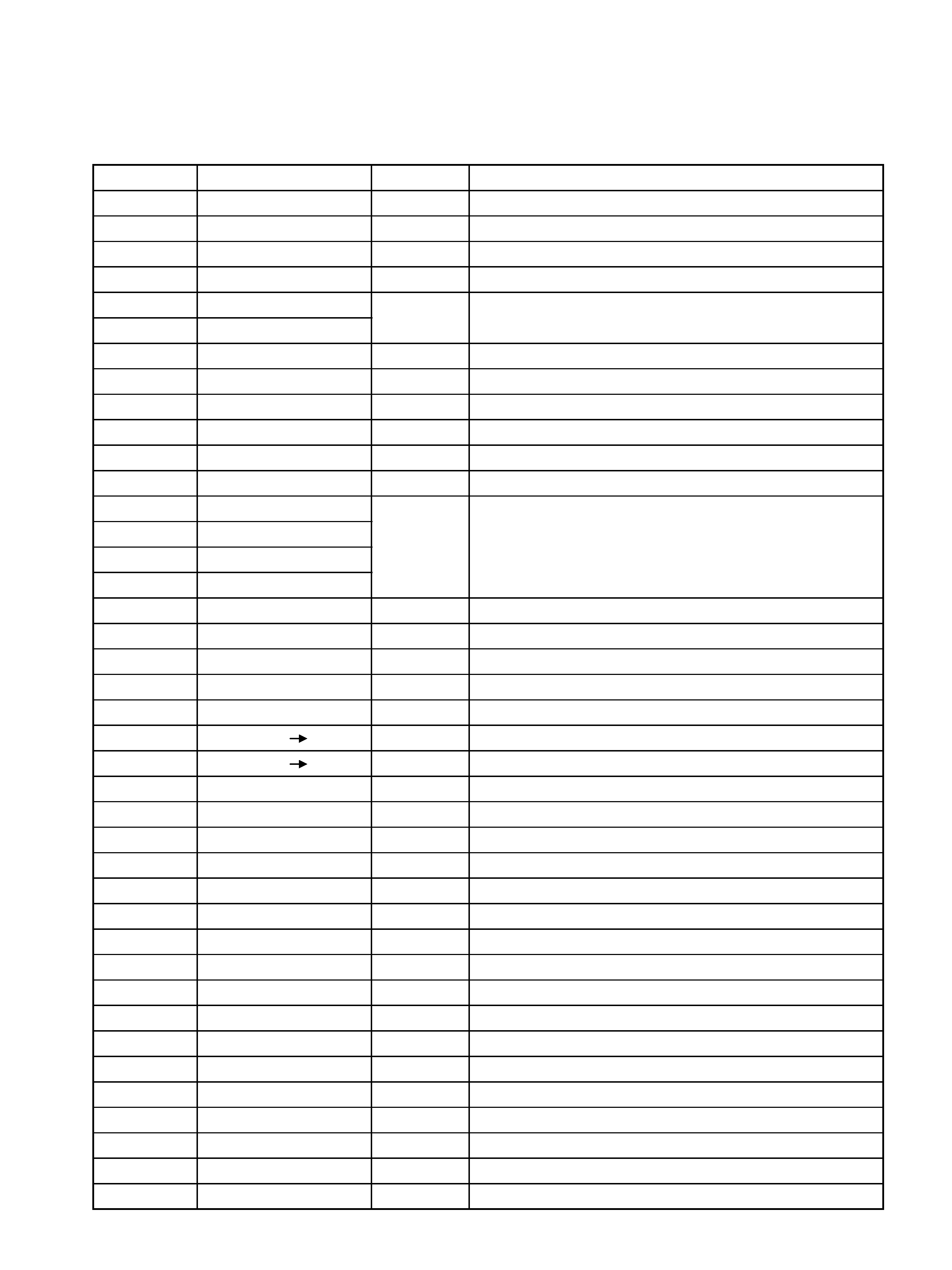
2 IC PIN FUNCTIONS
3
Pin No.
PIN NAME
I/O
1
FUNC MUTE
O
Function, Mute ON/OFF Output
2
-20dB MUTE
O
-20dB Mute ON/OFF Output
3
POWER MUTE
O
Power Mute Output
4
SOURCE REC, OUT
O
Source recoding Output
5
OPTION
6
OPTION
7
PROTECT IN
I
Protect Input
8
STAND BY
O
Stand by LED ON/OFF Output
9
POWER ON/OFF
O
Power ON/OFF Output
10
AUX
O
Function, LED ON/OFF Output
11
PHONO
O
Function, LED ON/OFF Output
12
N/C
-
Non connection
13
TUNER
14
CD
15
TAPE 1
16
TAPE 2
17
Vss
I
GROUND
18,19
N/C
-
Non connection
20
RESET
I
Divice reset pluse input
21
XL 1
O
Crystal Output
22
XL 2
I
Crystal Input
23
TAPE 2
1
O
TAPE 2 Recording Output
24
TAPE 1
2
O
TAPE 1 Recording Output
25,26
KEY OUT
O
Key matrix signal Output
27,28
KEY IN
I
Key matrix signal Input
29
TAPE 2 REC IN
I
TAPE 2 Recording Input
30
TAPE 1 REC IN
I
TAPE 1 Recording Input
31
SOURCE REC, IN
I
Source recoding Input
32,34
N/C
-
Non connection
33
FUNCTION DOWN
I
Function Down Input
35
FUNCTION UP
I
Function Up Input
36
BUS IN
I
System control Input
37
REMOTE IN
I
Remote control Input
38
N/C
-
Non connection
39
Vdd
I
+5V
40
BUS OUT
O
System control Output
41
N/C
-
Non connection
42
VOLUME DOWN
O
Volume DOWN Output
43
VOLUME UP
O
Volume UP Output
44
CD DIRECT
O
CD Direct led ON/OFF Output
DESCRIPTION
Option port "HIGH" LEVEL
Function, LED ON/OFF Output
O
I
HVIANAM1224A
4
2
1
3
4
5
8
7
6
9
10
11
12
13
14
15
18
16
17
19
20
21
24
23
22
29
25
26
27
32
28
31
33
34
35
36
x7
x4
x4
x3
x3
x3
30
x3
37
38
39
40
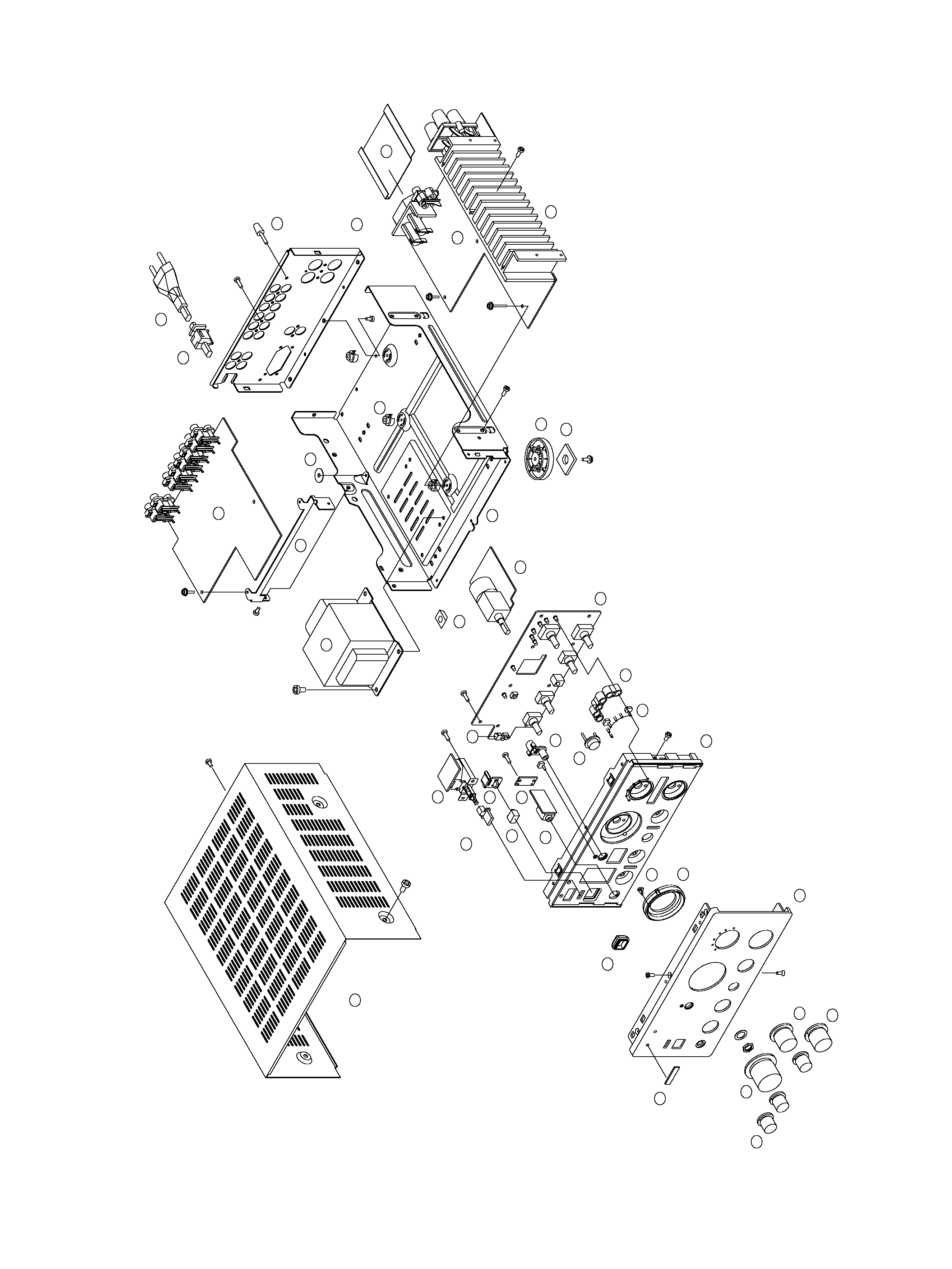
3 EXPLODED VIEWS AND PARTS LIST

5
EXPLODED VIEW LIST
£
£
£
£
£
INCLUDED ACCESSORIES