
9A10505400
AV Digital Home Theater Receiver
OWNER'S MANUAL
Z
AG-D8850
2
IMPORTANT SAFETY INSTRUCTIONS
1) Read these instructions.
2) Keep these instructions.
3) Heed all warnings.
4) Follow all instructions.
5) Do not use this apparatus near water.
6) Clean only with dry cloth.
7) Do not block any ventilation openings. Install in accordance
with the manufacturer's instructions.
8) Do not install near any heat sources such as radiators, heat
registers, stoves, or other apparatus (including amplifiers) that
produce heat.
9) Do not defeat the safety purpose of the polarized or
grounding-type plug. A polarized plug has two blades with
one wider than the other. A grounding type plug has two
blades and a third grounding prong. The wide blade or the
third prong are provided for your safety. If the provided plug
does not fit into your outlet, consult an electrician for
replacement of the obsolete outlet.
10) Protect the power cord from being walked on or pinched
particularly at plugs, convenience receptacles, and the point
where they exit from the apparatus.
11) Only use attachments/accessories specified by the
manufacturer.
12) Use only with the cart, stand, tripod,
bracket, or table specified by the
manufacturer, or sold with the apparatus.
When a cart is used, use caution when
moving the cart/apparatus combination to
avoid injury from tip-over.
13) Unplug this apparatus during lightning storms or when
unused for long periods of time.
14) Refer all servicing to qualified service personnel. Servicing is
required when the apparatus has been damaged in any way,
such as power-supply cord or plug is damaged, liquid has
been spilled or objects have fallen into the apparatus, the
apparatus has been exposed to rain or moisture, does not
operate normally, or has been dropped.
<
Do not expose this apparatus to drips or splashes.
<
Do not place any objects filled with liquids, such as vases, on
the apparatus.
<
Do not install this apparatus in a confined space such as a
book case or similar unit.
<
The apparatus draws nominal non-operating power from the
AC outlet with its STANDBY/ON switch in the standby
position.
<
The apparatus should be located close enough to the AC
outlet so that you can easily grasp the power cord plug at any
time.
<
An apparatus with Class ! construction shall be connected to
an AC outlet with a protective grounding connection.
<
Batteries (battery pack or batteries installed) shall not be
exposed to excessive heat such as sunshine, fire or the like.
CAUTION
<
DO NOT REMOVE THE EXTERNAL CASES OR CABINETS TO
EXPOSE THE ELECTRONICS. NO USER SERVICEABLE PARTS
ARE WITHIN!
<
IF YOU ARE EXPERIENCING PROBLEMS WITH THIS PRODUCT,
CONTACT TEAC FOR A SERVICE REFERRAL. DO NOT USE THE
PRODUCT UNTIL IT HAS BEEN REPAIRED.
CAUTION: TO REDUCE THE RISK OF ELECTRIC SHOCK,
DO NOT REMOVE COVER (OR BACK). NO USER-
SERVICEABLE PARTS INSIDE. REFER SERVICING TO
QUALIFIED SERVICE PERSONNEL.
The lightning flash with arrowhead symbol, within an
equilateral triangle, is intended to alert the user to the
presence of uninsulated "dangerous voltage" within the
product's enclosure that may be of sufficient magnitude
to constitute a risk of electric shock to persons.
The exclamation point within an equilateral triangle is
intended to alert the user to the presence of important
operating and maintenance (servicing) instructions in the
literature accompanying the appliance.
WARNING: TO PREVENT FIRE OR SHOCK
HAZARD, DO NOT EXPOSE THIS APPLIANCE
TO RAIN OR MOISTURE.
Disposal of your old appliance
1. When this crossed-out wheeled bin
symbol is attached to a product it means
the product is covered by the European
Directive 2002/96/EC.
2. All electrical and electronic products
should be disposed of separately from
the municipal waste stream via designated collection
facilities appointed by the government or the local
authorities.
3. The correct disposal of your old appliance will help prevent
potential negative consequences for the environment and
human health.
4. For more detailed information about disposal of your old
appliance, please contact your city office, waste disposal
service or the shop where you purchased the product.
For European customers
3
CAUTION Regarding Placement
To maintain proper ventilation, be sure to leave a space
around the unit (from the largest outer dimensions including
projections) equal to, or greater than, shown below.
Left and Right Panels: 5 cm
Rear Panel: 10 cm
Top Panel: 20 cm
"DTS" and "DTS Digital Surround" are registered trademarks
of Digital Theater Systems, Inc.
Manufactured under license from Dolby Laboratories. Dolby,
Pro Logic and the double-D symbol are trademarks of Dolby
Laboratories.
Before Use
Read this before operation
<
As the unit may become warm during operation, always leave
sufficient space around the unit for ventilation.
The ventilation holes should not be covered. Make sure there
is at least 20 cm of space above and at least 5 cm of space on
each side of the unit. Do NOT place anything on top of the
unit.
<
The voltage supplied to the unit should match the voltage as
printed on the rear panel. If you are in any doubt regarding
this matter, consult an electrician.
<
Choose the installation location of your unit carefully. Avoid
placing it in direct sunlight or close to a source of heat. Also
avoid locations subject to vibrations and excessive dust, heat,
cold or moisture.
<
Do not place the unit on the amplifier/receiver.
<
Do not open the cabinet as this might result in damage to the
circuitry or electrical shock. If a foreign object should get into
the unit, contact your dealer or service company.
<
When removing the power plug from the wall outlet, always
pull directly on the plug, never yank the cord.
<
Do not attempt to clean the unit with chemical solvents as
this might damage the finish. Use a clean, dry or slightly
damp cloth.
<
Keep this manual in a safe place for future reference.
Contents
Thank you for choosing TEAC. Read this manual carefully
to get the best performance from this unit.
Contents. . . . . . . . . . . . . . . . . . . . . . . . . . . . . . . . . . . . . . . . . . 3
Before Use . . . . . . . . . . . . . . . . . . . . . . . . . . . . . . . . . . . . . . . . 3
Connection (FM antenna) . . . . . . . . . . . . . . . . . . . . . . . . . . . . . 4
Connection (AM antenna). . . . . . . . . . . . . . . . . . . . . . . . . . . . . 5
Connection. . . . . . . . . . . . . . . . . . . . . . . . . . . . . . . . . . . . . . . . 6
Speaker Connections . . . . . . . . . . . . . . . . . . . . . . . . . . . . . . . 10
Positioning of the Speakers . . . . . . . . . . . . . . . . . . . . . . . . . . . 11
Restoring factory settings . . . . . . . . . . . . . . . . . . . . . . . . . . . . 11
Names of Each Control . . . . . . . . . . . . . . . . . . . . . . . . . . . . . . 12
Remote Control Unit. . . . . . . . . . . . . . . . . . . . . . . . . . . . . . . . 15
Basic Operation. . . . . . . . . . . . . . . . . . . . . . . . . . . . . . . . . . . . 16
Recording a Source . . . . . . . . . . . . . . . . . . . . . . . . . . . . . . . . . 19
Surround Mode . . . . . . . . . . . . . . . . . . . . . . . . . . . . . . . . . . . 20
Stereo Mode. . . . . . . . . . . . . . . . . . . . . . . . . . . . . . . . . . . . . . 22
Dynamic Range Compression . . . . . . . . . . . . . . . . . . . . . . . . . 22
DOLBY PRO LOGIC II parameters. . . . . . . . . . . . . . . . . . . . . . . 23
Tuner . . . . . . . . . . . . . . . . . . . . . . . . . . . . . . . . . . . . . . . . . . . 24
Preset Tuning . . . . . . . . . . . . . . . . . . . . . . . . . . . . . . . . . . . . . 25
RDS . . . . . . . . . . . . . . . . . . . . . . . . . . . . . . . . . . . . . . . . . . . . 26
RDS Search . . . . . . . . . . . . . . . . . . . . . . . . . . . . . . . . . . . . . . . 26
Setup . . . . . . . . . . . . . . . . . . . . . . . . . . . . . . . . . . . . . . . . . . . 28
Setup Menu Chart . . . . . . . . . . . . . . . . . . . . . . . . . . . . . . . . . 29
Settings . . . . . . . . . . . . . . . . . . . . . . . . . . . . . . . . . . . . . . . . . . .
System . . . . . . . . . . . . . . . . . . . . . . . . . . . . . . . . . . . . . . . . 30
Input . . . . . . . . . . . . . . . . . . . . . . . . . . . . . . . . . . . . . . . . . 30
Speaker Setup . . . . . . . . . . . . . . . . . . . . . . . . . . . . . . . . . . 31
Channel Level. . . . . . . . . . . . . . . . . . . . . . . . . . . . . . . . . . . 32
Parameters . . . . . . . . . . . . . . . . . . . . . . . . . . . . . . . . . . . . . 32
Test Tone . . . . . . . . . . . . . . . . . . . . . . . . . . . . . . . . . . . . . . . . 33
Troubleshooting . . . . . . . . . . . . . . . . . . . . . . . . . . . . . . . . . . . 35
Specifications . . . . . . . . . . . . . . . . . . . . . . . . . . . . . . . . . . . . . 36
4
Connection (FM antenna)
CAUTION:
<
Turn off the power of all the equipment before making
connections.
<
Read instructions of each component you intend to use with
this unit.
<
Be sure to insert each plug securely. To prevent hum and
noise, do not bundle the connection cords with the power
cord or speaker cables.
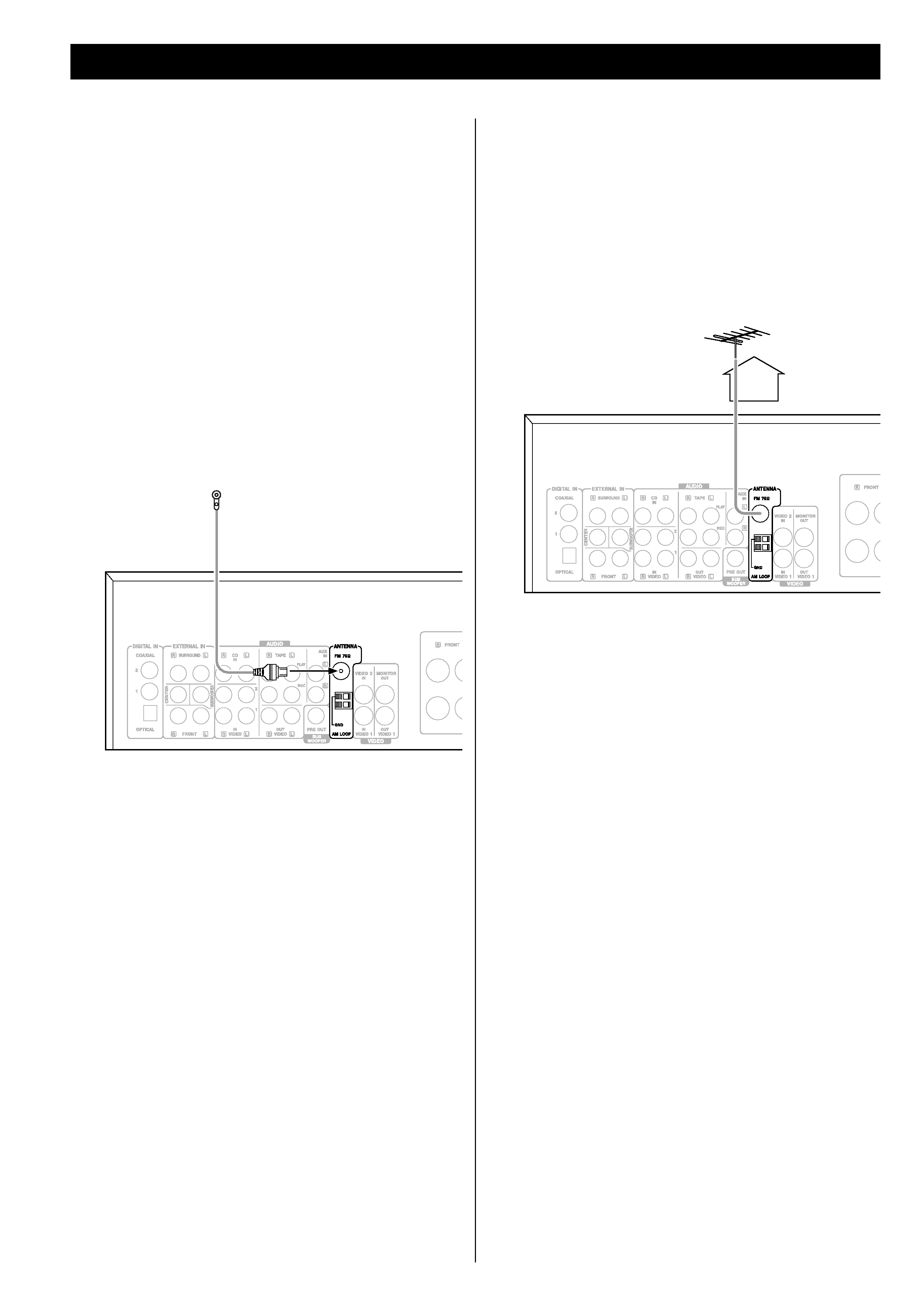
FM Indoor Antenna
Connect the lead-type FM antenna to the "FM 75" socket,
extend the lead and tune the tuner to your favorite FM station
(see page 24). Adjust the antenna in a suitable location like a
window frame or wall until the reception is best and then affix
the antenna in that position using thumb tacks, push pins or any
other suitable means.
FM Outdoor Antenna
In an area where FM signals are weak, it will be necessary to
use an 75-ohm unbalanced-type outdoor FM antenna.
Generally, a 3-element antenna will be sufficient; if you live in
an area where the FM signals are particularly weak, it may be
necessary to use one with 5 or more elements.
<
Disconnect the FM indoor antenna when using an outdoor
antenna.
5
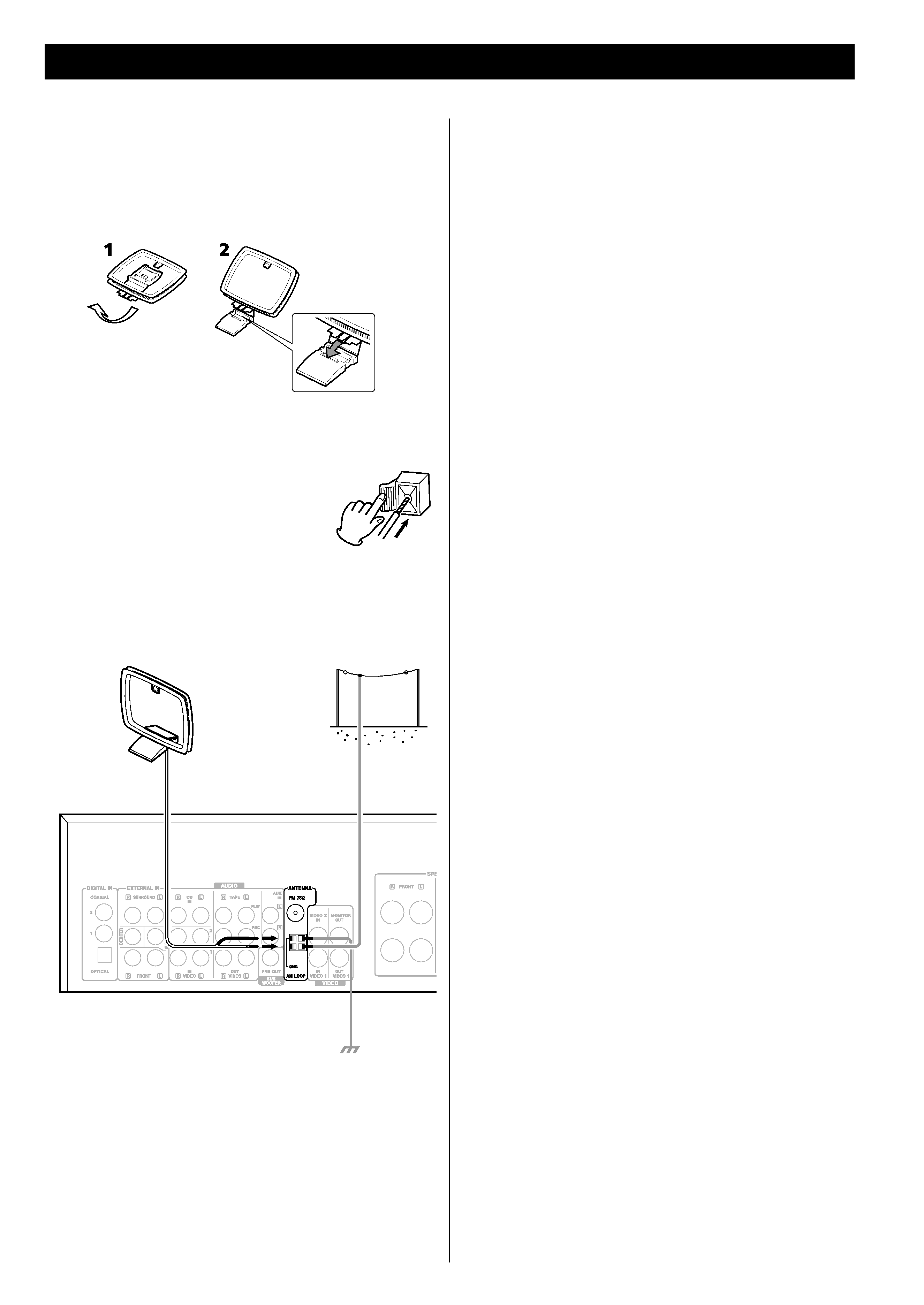
Connection (AM antenna)
How to connect:
Connect the loop antenna's wires to the AM antenna
terminals.
Make sure to connect:
white wire q lower terminal
black wire q upper terminal (GND)
Place the antenna on a shelf or hang it on a window frame,
etc., in the direction which gives the best reception. Keep all
other wires such as power cords, speaker wires or
interconnect wires as far away as possible from the antenna.
AM Indoor Loop Antenna
The high-performance AM loop antenna provided with this
unit is sufficient for good reception in most areas.
To stand the loop antenna on a surface, fix the claw to the
slot in the antenna base.
AM Loop
Antenna
AM Outdoor
Antenna
AM Outdoor Antenna
If the AM loop antenna provided does not deliver sufficient
reception (often due to being too far from the transmitter or
in a concrete building, etc.), it may be necessary to use an
outdoor AM antenna.
Use either a high quality commercial AM antenna or, if not
available, an insulated wire more than 5 m long, strip one
end, and connect this to the terminal as shown.
The antenna wire should be strung outdoors or indoors near
a window. For better reception, connect the GND terminal to
a reliable ground.
Note:
Even when using an outdoor AM antenna, do not disconnect
the AM loop antenna.