PC board shown are viewed from parts side.
The parts with no reference number or no parts number
in the exploded views are not supplied.
As regards the resistors and capacitors, refer to the
circuit diagrams contained in this manual.
Parts marked with this sign are safety critical
components. they must be replaced with identical
ensure exact replacement.
!
components - refer to the appropriate parts list and
1 SPECIFICATIONS
2
3 EXPLODED VIEW AND PARTS LIST
4 PC BOARDS AND PARTS LISTS
5 WIRING DIAGRAM
6 INCLUDED ACCESSORIES
3
5
8
17
19
2 ADJUSTMENT AND CHECKS
AG-D8800
AM/FM STEREO RECEIVER
TEAC
[E]: EUROPE. [HKG]: HONG KONG
[SAF]: SOUTH AFRICA [AUS]: AUSTRALIA

1 SPECIFICATIONS
AG-D8800
AMPLIFIER Section
Output Power:
100+100 W (Stereo 0.7% THD,40Hz to 20 kHz,6 ohms)
Total Harmonic Distortion:
Audio Input Sensitivity/Impedance:
0.09% (at 100 W, 1kHz, 6 ohms)
200 mV/22 k ohms
*LINE: 200 mV/47 k ohms
Frequency Response:
*LINE: 20 Hz - 50 kHz, +0/-3 dB
Signal -to-Noise Ratio
*LINE: 92 dB (IHF-A)
Tone Control:
BASS: +/- 10 dB at 100 Hz, TREBLE: +/- 10 dB at 10 kHz
FM Tuner Section
Tuning Range:
87.5 MHz - 108.0 MHz (50 kHz steps)
Total Harmonic Distortion (1 kHz):
Mono: 0.5% , Stereo: 0.8%
Frequency Response:
30 Hz - 15 kHz, +/- 3dB
Stereo Separation (1 kHz):
Signal-to- Noise Ratio:
Mono: 70 dB / Stereo: 65 dB
(Without notes 100.1 MHz, 65 dBf)
AM Tuner Section
Tuning Range:
522 kHz - 1,611 kHz (9 kHz steps)
Usable Sensitivity :
Signal -to-Noise Ratio :
Total Harmonic Distortion :
120 W + 120 W ( 6 ohms, JEITA)
Surround Output Power
125 W per channel (0.7% THD, 1kHz, 6 ohms, only one channel driven)
150 W per channel (6 ohms, JEITA)
Output Level / Impedance (TAPE REC):
Digital Audio Section
Sampling Frequency:
32 kHz, 44.1 kHz, 48 kHz, 96 kHz
Digital Input Level:
COAXIAL ( 75 ohms): 0.5 Vp-p
Video Section
Output Level:
1 Vp-p (75 ohms)
Jacks:
RCA Jack
GENERAL
Power Requirements:
AC 230V ,50 Hz
Dimension (W x H x D ):
Weight:
Standard Accessories:
AM Loop Antenna x 1
FM Matching Transformer x 1
440 x 141 x 330 mm
9.9 kg
Instruction Booklet x 1
FM (T) Type Antenna x 1
Power Consumption:
200 W (STANDBY: 3 W or less)
AC Outlets(expect Australia model, total 100 W max):
Remote Control Unit (RC-1040 or RC-1042) x1
* LINE means CD, TAPE,VIDEO
Switched x 1
BATTERY (AAA, R03, UM-4) x 2
Design and specifications are subject to change without notice.
Illustrations may differ slightly from production model.
Weight and dimensions are approximate.
42 dB
500 uV/m
1.5 % at 100 dB/m
40 dB at 100 dB/m
AG-D8800
3
2 ADJUSTMENTS AND CHECKS
Use a screwdriver with a plastic or ceramic grip for all adjustment.
2-1 TUNER SECTION
2-2 Adjustment and Test Points
1. Output of signal generation should not be greater than necessary to obtain an optimum output reading.
2-1-2 FM adjustment
3. Signal frequency: 1kHz / Deviation: 75 kHz
4. Modulation frequency : 90 MHz, 98 MHz, 106 MHz
5. Switch: press the BAND Buton to FM
2. Signal generation modulation: MAIN: 90%, PILOT: 10%
1. Output of signal generator should not be greater than necessary to obtain an optimum output reading.
3. Signal frequency: 400Hz
4. Modulator frequency: 603, 999, 1404kHz
2-1-1 AM adjustment
2. Signal generator modulation: 30%
5. Switch: press the BAND Button to AM
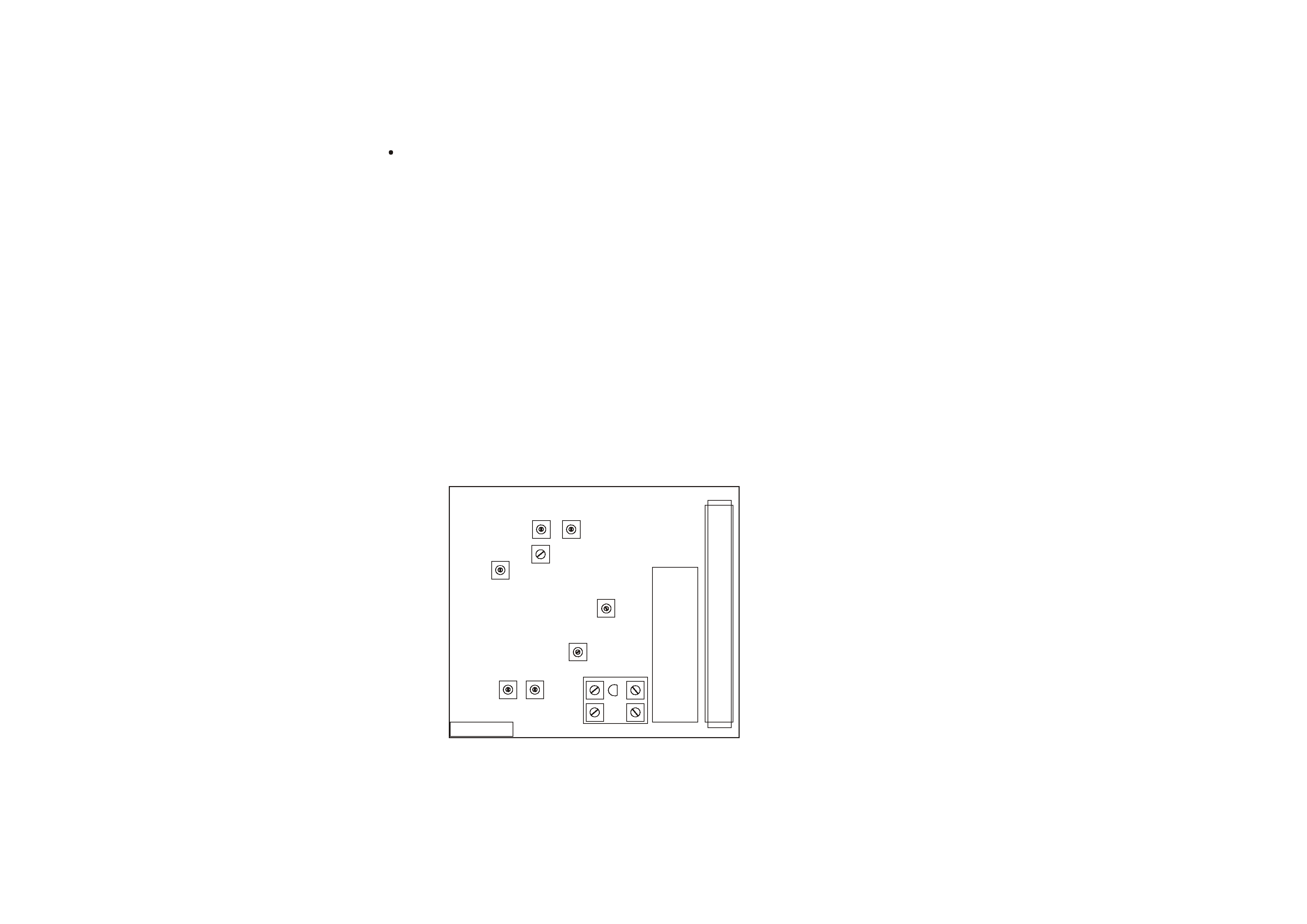
Fig. 2-2-1
SVR03
SVR01
SVR02
IF BLOCK
A
M
/
F
M
A
N
T
RF BLOCK
FD1
F
M
T
U
N
E
R
1
13
FD2
TUNER PCB
4
AG-D8800
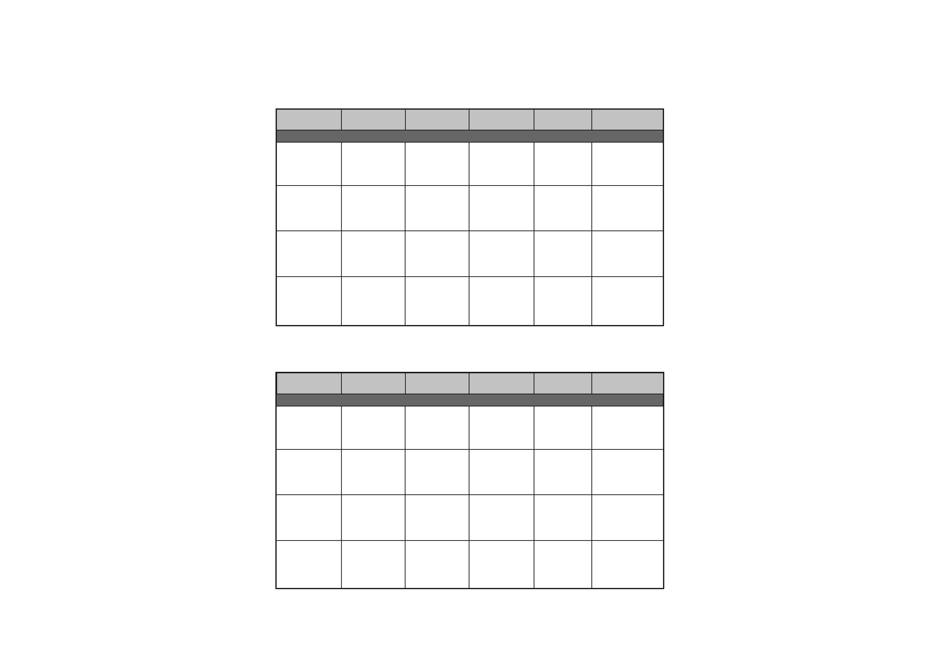
2-2-2 AM Tuner
STEP
Equipment
Signal generator
Set frequency
AM
2. RF Tracking
3. IF Tracking
Tuned on point
603kHz
1. Tuning voltage
DC voltmeter
4. Seek level
setting
setting
connection
Adjust point
Adjust for
522kHz
OSC coil
520kHz: 1.1~1.3V
1710kHz: 7.2~8.5V
AC voltmeter
ANT coil
RF BLOCK
Maximize audio
output repeat LOW,
HIGH frequency
oscilloscope
tape monitor L/R
IF BLOCK
Coil KSNT-1041
AC voltmeter
oscilloscope
tape monitor L/R
output
AC voltmeter
oscilloscope
tape monitor L/R
SVR 03
2-2-3 FM Tuner
STEP
Equipment
Signal generator
Set frequency
FM
2. FM DET.0V
3. Seek stop level
Push the signal
1. Tuning voltage
DC voltmeter
4. STEREO
setting
setting
connection
Adjust point
Adjust for
87.5 MHz
FD1, FD2, R17
87.5MHz: 1.35~1.65V
108MHz: 6.5~8.5V
AC voltmeter
Maximize 0V and
oscilloscope
tape monitor L/R
SVR01
AC voltmeter
oscilloscope
tape monitor L/R
Scan stop point to
AC voltmeter and
scope to tape
monitor of L/R
MIX coil CO4
108 MHz
87.5 MHz
108 MHz
(DC 1.2 +/- 0.1V)
18 dBu (TUNED)
FL display
distortion
or L-CH button
SVR02
Separation
and
Distortion Adj
DC voltmeter
indicator lights on
generator R-CH
channel
98.1 MHz
98.1 MHz
98.1 MHz
522kHz
603kHz
603kHz
603kHz
603kHz
603kHz
Maximize audio
(DC1.2V +/- 0.1V)
98.1 MHz
98.1 MHz
98.1 MHz
RF BLOCK
2
S
7
S
2
S
2
S
2
S
2
S
2
S
9
1-
2
S
4-
2
S
7
S
2
S
2
S
5
1-
5
S
2
-
6
S
2-
1
S
2
-
6
S
0
1-
2
S
4-
4
S
2
S
7-
3
S
2
S
1
S
1
S
1
S
1
S
1
S
2
S
2
S
1
S
1
S
1
S
1
S
S
N
A
R
T
1
10
4
(x2)
11
5
9
17
19
19
19
19
42
21
20
23
23
23
23
23
23
22
40
39
41
2
3
13
12
16
6
8
8
7
18
18
25
29
32
30
31
33
37
36
35
15
14
24
38
26
34
27
28
5
AG-D8800
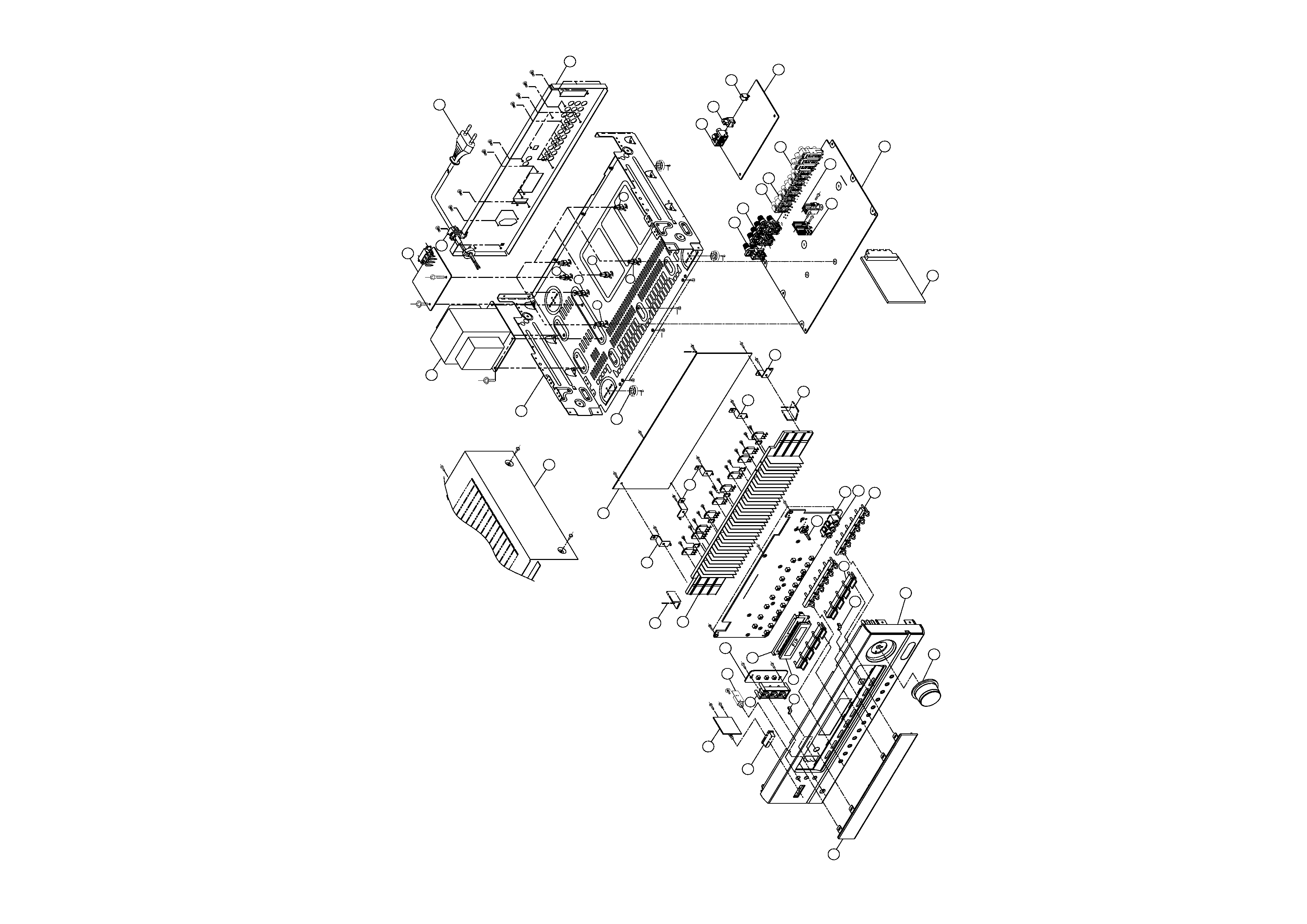
3. EXPLODED VIEWS AND PARTS LIST