OWNER'S MANUAL
9A09987400
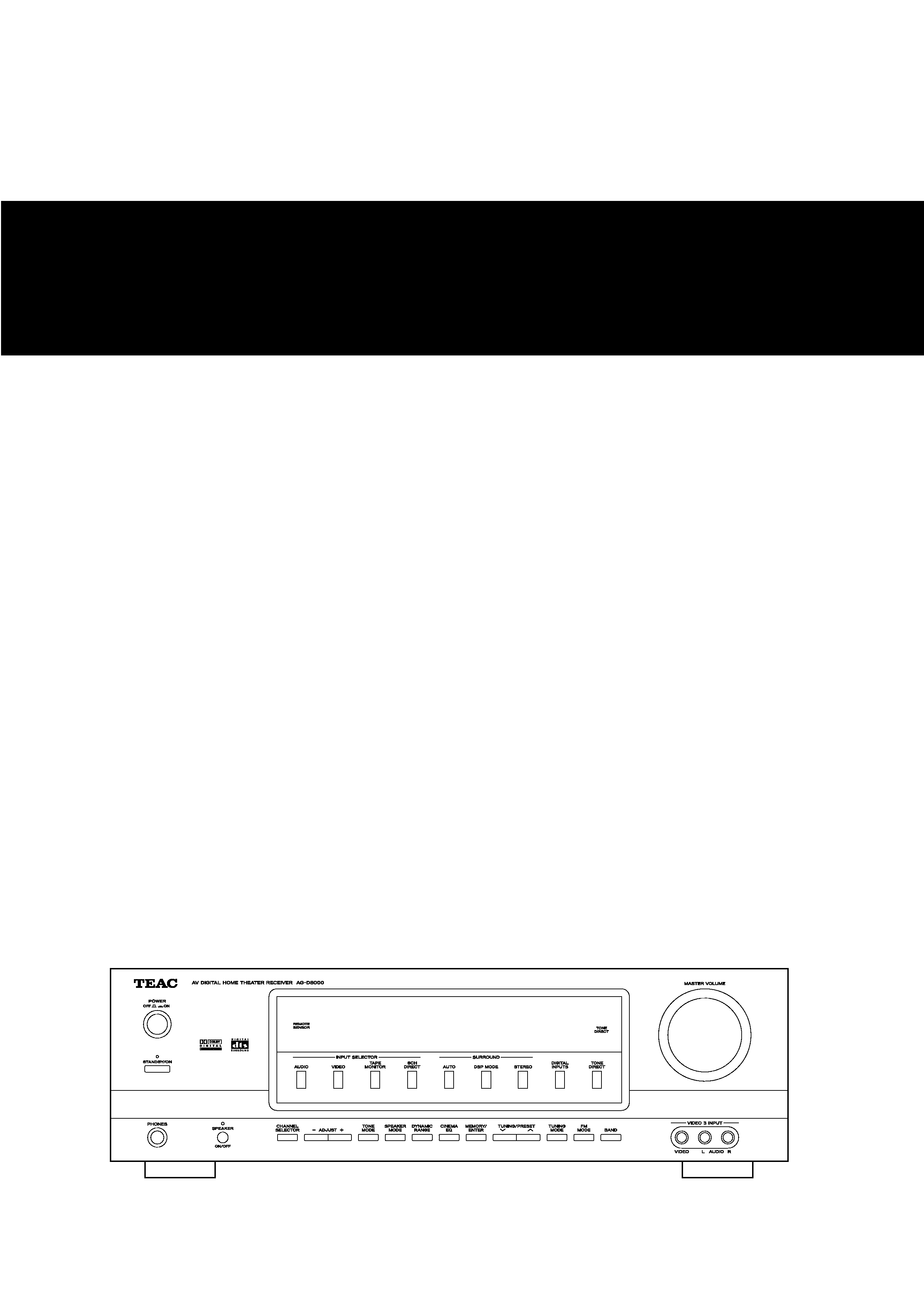
AV Digital Home Theater Receiver
Z
AG-D8000
Thank you for choosing TEAC. Read this manual carefully to get the best performance from this unit.
2
CAUTION
The product shall not be exposed to dripping or splashing and
that no object filled with liquids, such as vases, shall be placed
on the product.
Do not install this equipment in a confined space such as a
book case or similar unit.
CAUTION Regarding Placement
To maintain proper ventilation, be sure to leave a space
around the unit (from the largest outer dimensions including
projections) equal to, or greater than, shown below.
Left and Right Panels: 5 cm
Rear Panel: 10 cm
Top Panel: 20 cm
"DTS" and "DTS Digital Surround" are trademarks of Digital
Theater Systems, Inc. ©1996 Digital Theater Systems, Inc. All
rights reserved.
Manufactured under license from Dolby Laboratories.
"Dolby", "Pro Logic" and the double-D symbol are
trademarks of Dolby Laboratories.
Before Use
Read this before operation
<
As the unit may become warm during operation, always leave
sufficient space around the unit for ventilation.
The ventilation holes should not be covered. Make sure there
is at least 20 cm of space above and at least 5 cm of space on
each side of the unit. Do NOT place anything on top of the
unit.
<
The voltage supplied to the unit should match the voltage as
printed on the rear panel. If you are in any doubt regarding
this matter, consult an electrician.
<
Choose the installation location of your unit carefully. Avoid
placing it in direct sunlight or close to a source of heat. Also
avoid locations subject to vibrations and excessive dust, heat,
cold or moisture.
<
Do not place the unit on the amplifier/receiver.
<
Do not open the cabinet as this might result in damage to the
circuitry or electrical shock. If a foreign object should get into
the unit, contact your dealer or service company.
<
When removing the power plug from the wall outlet, always
pull directly on the plug, never yank the cord.
<
Do not attempt to clean the unit with chemical solvents as
this might damage the finish. Use a clean, dry or slightly
damp cloth.
<
Keep this manual in a safe place for future reference.
Before Use . . . . . . . . . . . . . . . . . . . . . . . . . . . . . . . . . . . . . . . . 2
Connection (AM antenna). . . . . . . . . . . . . . . . . . . . . . . . . . . . . 3
Connection (FM antenna) . . . . . . . . . . . . . . . . . . . . . . . . . . . . . 3
Connection. . . . . . . . . . . . . . . . . . . . . . . . . . . . . . . . . . . . . . . . 4
Speaker Connections . . . . . . . . . . . . . . . . . . . . . . . . . . . . . . . . 8
Positioning of the Speakers . . . . . . . . . . . . . . . . . . . . . . . . . . . . 9
Remote Control Unit. . . . . . . . . . . . . . . . . . . . . . . . . . . . . . . . . 9
Names of Each Control . . . . . . . . . . . . . . . . . . . . . . . . . . . . . . 10
Speaker Configuration
Speaker Setting . . . . . . . . . . . . . . . . . . . . . . . . . . . . . . . . . 12
Delay Time . . . . . . . . . . . . . . . . . . . . . . . . . . . . . . . . . . . . . 13
Test Tone . . . . . . . . . . . . . . . . . . . . . . . . . . . . . . . . . . . . . . 14
Channel Selector . . . . . . . . . . . . . . . . . . . . . . . . . . . . . . . . 15
Basic Operation. . . . . . . . . . . . . . . . . . . . . . . . . . . . . . . . . . . . 16
Recording a Source . . . . . . . . . . . . . . . . . . . . . . . . . . . . . . . . . 19
Surround Mode . . . . . . . . . . . . . . . . . . . . . . . . . . . . . . . . . . . 20
Stereo Mode. . . . . . . . . . . . . . . . . . . . . . . . . . . . . . . . . . . . . . 22
Dynamic Range Compression . . . . . . . . . . . . . . . . . . . . . . . . . 22
DOLBY PRO LOGIC II parameters. . . . . . . . . . . . . . . . . . . . . . . 23
Tuner . . . . . . . . . . . . . . . . . . . . . . . . . . . . . . . . . . . . . . . . . . . 24
Preset Tuning . . . . . . . . . . . . . . . . . . . . . . . . . . . . . . . . . . . . . 25
Troubleshooting . . . . . . . . . . . . . . . . . . . . . . . . . . . . . . . . . . . 26
Specifications . . . . . . . . . . . . . . . . . . . . . . . . . . . . . . . . . . . . . 27
Contents
3
Connection (FM antenna)
CAUTION:
<
Turn off the power of all the equipment before making
connections.
<
Read instructions of each component you intend to use with
this unit.
<
Be sure to insert each plug securely. To prevent hum and
noise, do not bundle the connection cords with the power
cord or speaker cables.
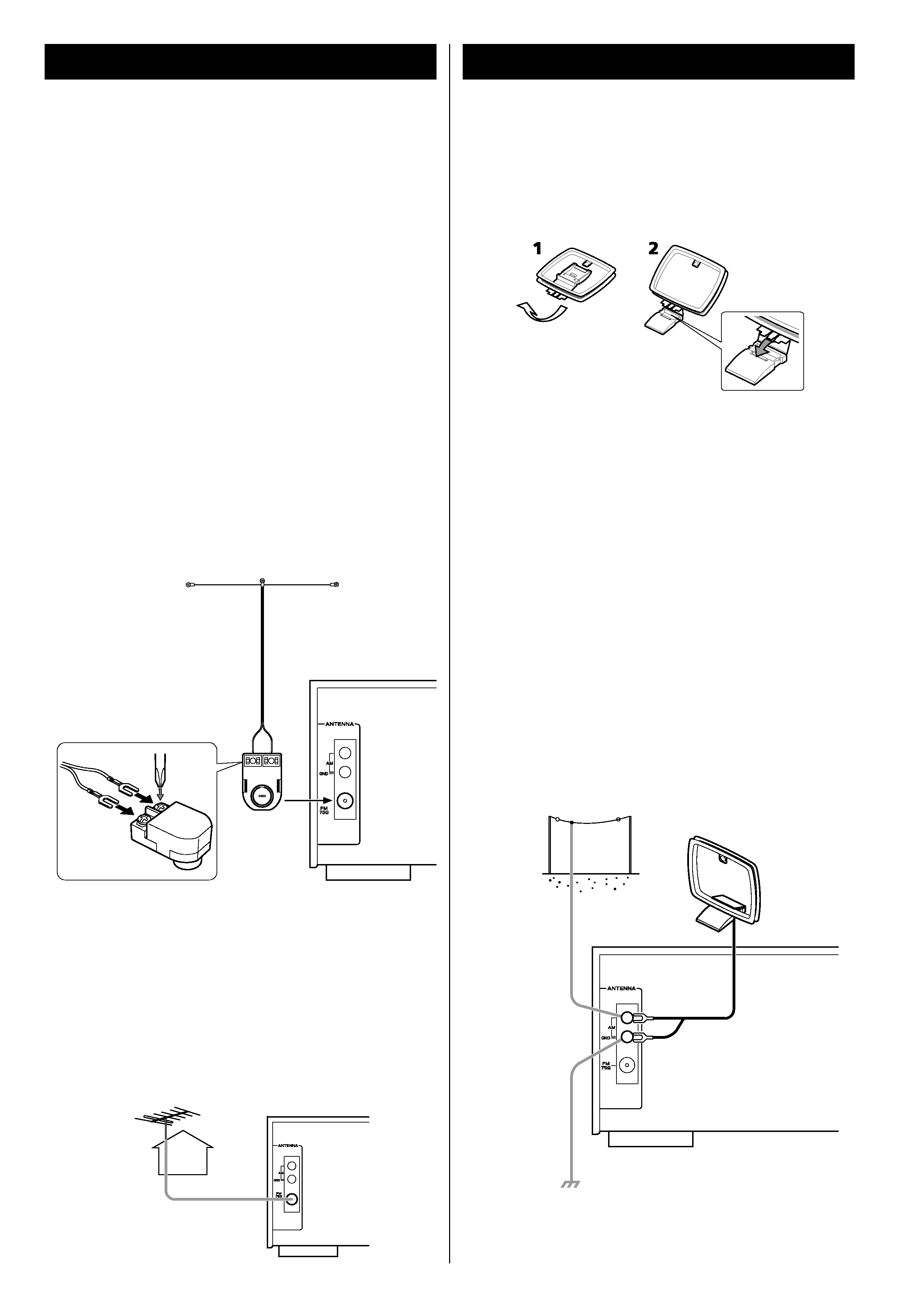
FM Indoor Antenna
In an area with strong FM signals, the T-type FM antenna
provided with this unit is sufficient.
Extend the antenna into a "T" shape and connect the two
wires at the base of the "T" to the provided matching
transformer, as shown.
After completing connection, plug the transformer into the
"FM 75" socket. Extend the top of the "T" and tune the
tuner to your favorite station (see page 24). Adjust the
antenna in a suitable location like a window frame or wall
until the reception is best and then affix the antenna in that
position using thumb tacks, push pins or any other suitable
means.
Connection (AM antenna)
How to connect:
Turn the AM terminal's cap counterclockwise to loosen it, put
the loop antenna's wire under the cap, and turn the cap
clockwise to securely connect the wire.
Make sure it is fastened securely by pulling the cord lightly.
Place the antenna on a shelf or hang it on a window frame,
etc., in the direction which gives the best reception. Keep all
other wires such as power cords, speaker wires or
interconnect wires as far away as possible from the antenna.
<
If the AM loop antenna provided does not deliver sufficient
reception (often due to being too far from the transmitter or
in a concrete building, etc.), it may be necessary to use an
outdoor AM antenna.
Use either a high quality commercial AM antenna or, if not
available, an insulated wire more than 5 m long, strip one
end, and connect this to the terminal as shown.
The antenna wire should be strung outdoors or indoors near
a window. For better reception, connect the GND terminal to
a reliable ground.
FM Outdoor Antenna
In an area where FM signals are weak, it will be necessary to
use an 75-ohm unbalanced-type outdoor FM antenna.
Generally, a 3-element antenna will be sufficient; if you live in
an area where the FM signals are particularly weak, it may be
necessary to use one with 5 or more elements.
<
Disconnect the FM indoor antenna when using an outdoor
antenna.
AM Indoor Loop Antenna
The high-performance AM loop antenna provided with this
unit is sufficient for good reception in most areas.
To stand the loop antenna on a surface, fix the claw to the
slot in the antenna base.
Note:
Even when using an outdoor AM antenna, do not disconnect
the AM loop antenna.
AM Loop
Antenna
AM Outdoor
Antenna
4
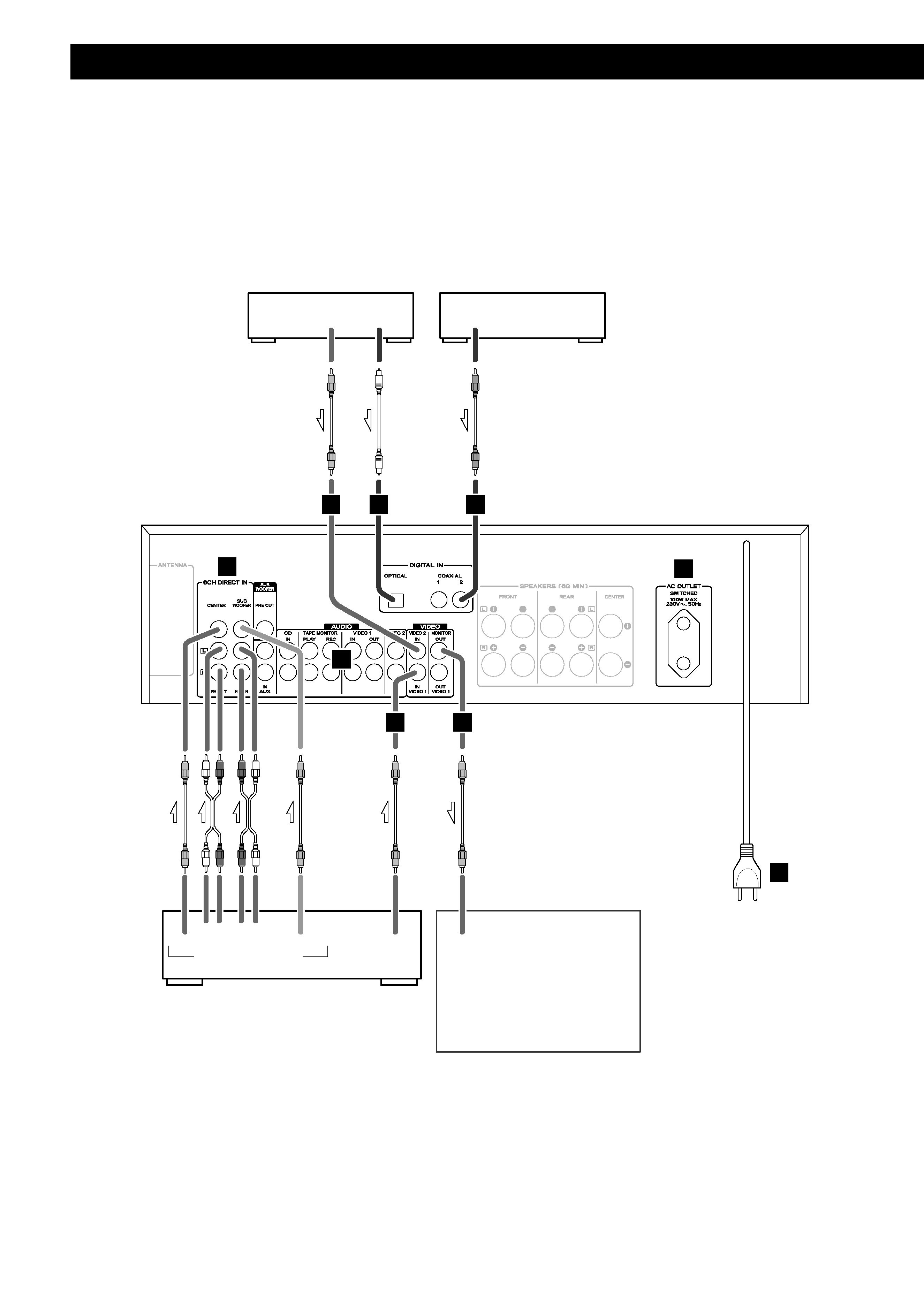
Connection
SURROUND
SUBWOOFER
FRONT
CENTER
5.1CH AUDIO OUT
VIDEO
OUT
VIDEO
IN
DVD player or Decoder
DVD, CD, etc.
AC outlet
DVD, CD, etc.
TV (Monitor)
R
RL
L
DIGITAL
OUT
DIGITAL
OUT
VIDEO
OUT
A
A
D
D
D
E
F
B
C

5
DIGITAL IN terminals
Used for the input of digital audio signals. Connect these digital input terminals to the
appropriate digital output terminals of the digital audio source unit such as a DVD or CD player.
Use a good quality RCA coaxial cable or optical digital cable.
<
When inserting the plug of the optical cable, the protective shutter of the terminal will open and
you should hear it click into position when fully inserted. Be careful that you do not force the
plug, because this could result in damage to the protective shutter, the cable, or the unit itself.
AUDIO IN/OUT jacks
Analog 2-channel audio signal is input or output from these jacks. Connect the component with
commercially-available RCA cables.
Make sure to connect :
white plug q white jack (L: left channel)
red plug q red jack (R: right channel)
6CH DIRECT IN jacks
If your DVD player or decoder has 6-channel analog audio outputs, connect them with good
quality RCA cables.
VIDEO jack
Connect the component with a high quality RCA cable designed for video applications.
AC OUTLET (switched)
Not available for Australian model.
This outlet is active only when the unit is on.
Caution:
Make sure that the total power consumption of all equipment connected to the outlet does not
exceed 100 watts.
AC Power Cord
After all other connections are complete, connect the plug to the AC wall socket.
If you are not going to use the unit for some time, disconnect the power cord from the wall
socket. (Leaving the power cord unconnected for longer than 14 days will cause the tuner
memory presets to be lost.)
Be sure to connect the power cord to an AC outlet which supplies the correct voltage.
Hold the power plug when plugging or unplugging the power cord.
F
E
D
C
B
A
CAUTION:
<
Turn off the power of all the equipment before making connections.
<
Read instructions of each component you intend to use with this unit.
<
Be sure to insert each plug securely. To prevent hum and noise, do not bundle the connection
cords with the power cord or speaker cables.