ag-d9100
`
Audio/Video Surround Receiver
9A06788300
This appliance has a serial number located
on the rear panel. Please record the model
number and serial number and retain them
for your records.
Model number
Serial number
WARNING: TO PREVENT FIRE OR SHOCK
HAZARD, DO NOT EXPOSE THIS
APPLIANCE TO RAIN OR MOISTURE.
The exclamation point within an equilateral triangle is intended to alert the user to the pres-
ence of important operating and maintenance (servicing) instructions in the literature
accompanying the appliance.
The lightning flash with arrowhead symbol, within an equilateral triangle, is intended to alert
the user to the presence of uninsulated "dangerous voltage" within the product's enclosure
that may be of sufficient magnitude to constitute a risk of electric shock to persons.
CAUTION: TO REDUCE THE RISK OF ELECTRIC SHOCK, DO NOT
REMOVE COVER (OR BACK). NO USER-SERVICEABLE PARTS INSIDE.
REFER SERVICING TO QUALIFIED SERVICE PERSONNEL.
Ü
ÿ
Y
OWNER'S MANUAL........................................... 2
MANUEL DUPROPRIETAIRE ......................... 28
BEDIENUNGSANLEITUNG .............................. 54
MANUALE DI ISTRUZIONI.............................. 80
MANUAL DEL USUARIO............................... 106
Thanks for buying a TEAC.
Read this manual carefully to get the best performance from
this unit.
Nous vous remercions pour l'achat d'un appareil TEAC.
Lire ce manuel avec attention pour obtenir les meilleures
perfor-mances possibles de cet appareil.
Vielen Dank für den Kauf dieses TEAC-Geräts.
Bitte lesen Sie diese Anleitung sorgfältig durch, um die
Leistungs-fähigkeit dieses Geräts optimal nutzen zu können.
Grazie per aver acquistato un prodotto TEAC.
Leggere attentamente questo manuale per ottenere le
migliori prestazioni da questo apparecchio.
Enhorabuena por la adquisición de un TEAC.
Lea detenidamente este manual a fin de obtener el mejor
rendimiento de esta unidad.
ENGLISH
FRANÇAIS
DEUTSCH
ITALIANO
ESPAÑOL
CONTENTS
PRECAUTIONS
2
Choose the installation location of your unit carefully.
Avoid placing it in direct sunlight or close to a source
of heat. Also avoid locations subject to vibrations and
excessive dust, heat, cold or moisture.
The ventilation holes should not be covered. Make
sure there is at least 50 cm (20 inches) of space
above and at least 10 cm (4 inches) of space beside
the amplifier/receiver. Do not place a CD player or
other equipment on top of the amplifier/receiver.
Do not open the cabinet as this might result in
damage to the circuitry or electrical shock. If a
foreign object should get into the set, contact your
dealer.
When removing the power plug from the wall outlet,
always pull directly on the plug, never yank the cord.
Do not attempt to clean the unit with chemical
solvents as this might damage the finish. Use a
clean, dry cloth.
Keep this manual in a safe place for future reference.
Read This Before Operating
PRECAUTIONS ................................................................... 2
Read This Before Operating ......................................... 2
CONNECTIONS .................................................................. 3
Connecting Audio Equipment ...................................... 3
Connecting Video Equipment ...................................... 4
Connecting the PRE OUT jacks .................................... 5
Connecting the VIDEO 3 INPUT Jacks......................... 6
Connecting Antennas.................................................... 6
Connecting Speaker Systems ...................................... 7
Connecting the AC Power ............................................ 7
CONTROLS AND INDICATORS ........................................ 8
AUDIO OPERATIONS ...................................................... 10
Sleep Timer Operation ............................................... 10
Basic Operations ......................................................... 10
Radio Reception .......................................................... 11
Preset Tuning............................................................... 13
RDS (Radio data System) ........................................... 14
Recording a Source..................................................... 17
VIDEO OPERATIONS ....................................................... 18
Playing Video Sources................................................ 18
Recording with a Video Deck ..................................... 18
SURROUND EFFECTS ..................................................... 19
Available Surround Modes ........................................ 19
Playing Surround Sound ............................................ 22
BACK-UP SYSTEM........................................................... 22
Back-up Memory Function ......................................... 22
REMOTE CONTROL UNIT ............................................... 23
Using the Remote Control Unit ................................. 23
Battery Installation ...................................................... 23
TEAC SYSTEM REMOTE-CONTROLLED
OPERATION...................................................................... 24
Using a CD Player and a Cassette Deck
with a REMOTE SENSOR Window ............................ 24
Buttons for the Operation of Other
TEAC Components ...................................................... 25
TROUBLESHOOTING ...................................................... 26
SPECIFICATIONS ............................................................. 27
IMPORTANT (for U.K. Customers)
DO NOT cut off the mains plug from this equipment.
If the plug fitted is not suitable for the power points
in your home or the cable is too short to reach a
power point, then obtain an appropriate safety
approved extension lead or consult your dealer.
If nonetheless the mains plug is cut off, remove the
fuse and dispose of the plug immediately, to avoid a
possible shock hazard by inadvertent connection to
the mains supply.
If this product is not provided with a mains plug, or
one has to be fitted, then follow the instructions
given below:
IMPORTANT. DO NOT make any connection to the
larger terminal which is marked with the letter E or
by the safety earth symbol
ç or coloured GREEN or
GREEN-and-YELLOW.
The wires in the mains lead on this product are
coloured in accordance with the following code:
BLUE:
NEUTRAL
BROWN:
LIVE
As these colours may not correspond with the
coloured markings identifying the terminals in
your plug proceed as follows:
The
wire
which
is
coloured
BLUE
must
be
connected to the terminal which is marked with the
letter N or coloured BLACK.
The wire which is coloured BROWN must be
connected to the terminal which is marked with the
letter L or coloured RED.
When replacing the fuse only a correctly rated
approved type should be used and be sure to re-fit
the fuse cover.
IF
IN
DOUBT
--
CONSULT
A
COMPETENT
ELECTRICIAN.
CAUTION Regarding Placement
(Except for U.S.A. And Canada)
To maintain proper ventilation, be sure to leave a
space around the unit (from the largest outer
dimensions including projections) equal to, or
greater than, shown below.
Left and Right Panels
: 10 cm
Rear Panel
: 10 cm
Top Panel
: 50 cm
ENGLISH
CONNECTIONS
3
CAUTION:
Do not plug the power cord of any component into AC
outlets and do not turn their POWER switches on until
all connections have been performed.
The cable connectors should be fully inserted into the
jacks. Loose connections may cause hum and noise.
Read the instructions for each component you intend
to use with the receiver.
L
L
R
R
White
White
White
Red
Red
Red
Audio connection cords
Center
Speaker
Right
Left
Right
Left
Right
Left
Rear Speaker
Front B Speaker
Front A Speaker
Tape Deck
LINE
OUT
LINE
OUT
LINE
IN
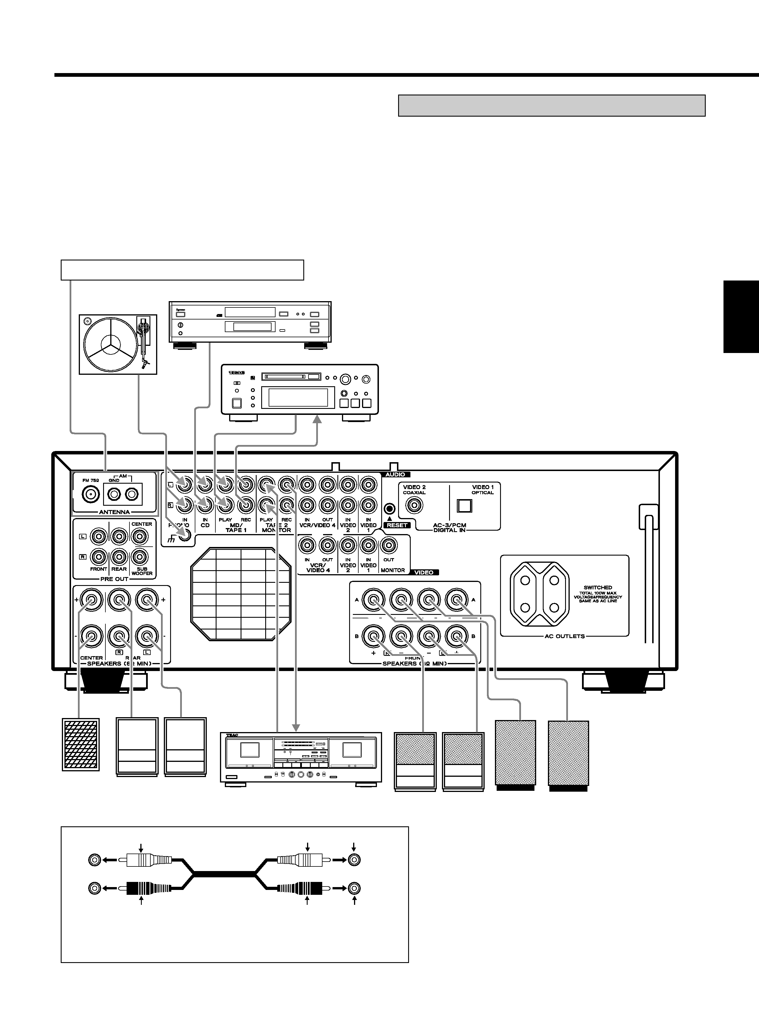
To make these connections, use interconnect cords with RCA plugs.
Make sure that you connect the white pin-plug to the white jacks
(left) and the red pin-plug to the red jacks (right).
+
Turntable
CD Player
Refer to "Connecting Antennas" on pages 6~7.
MD Deck or Tape Deck
LINE OUT
LINE
OUT
LINE IN
Connecting Audio Equipment
AUDIO signal jacks
PHONO jacks
Connect the turntable's output jacks to the PHONO IN
jacks.
CD IN jacks
Connect the CD player's output (LINE OUT) jacks to the
CD IN jacks.
MD/TAPE 1 (PLAY/REC) jacks
Connect the MD/TAPE1 jacks to the MD player or the cas-
sette deck.
... Connect the MD player or cassette deck output (LINE
OUT) jacks to the PLAY jacks.
... Connect the MD player or cassette deck input (LINE
IN) jacks to the REC jacks.
TAPE 2 (PLAY/REC) jacks
... Connect the cassette deck output (LINE OUT) jacks to
the PLAY (TAPE 2 MONITOR) jacks.
... Connect the cassette deck input (LINE IN) jacks to the
REC (TAPE 2 MONITOR) jacks.
4
CONNECTIONS
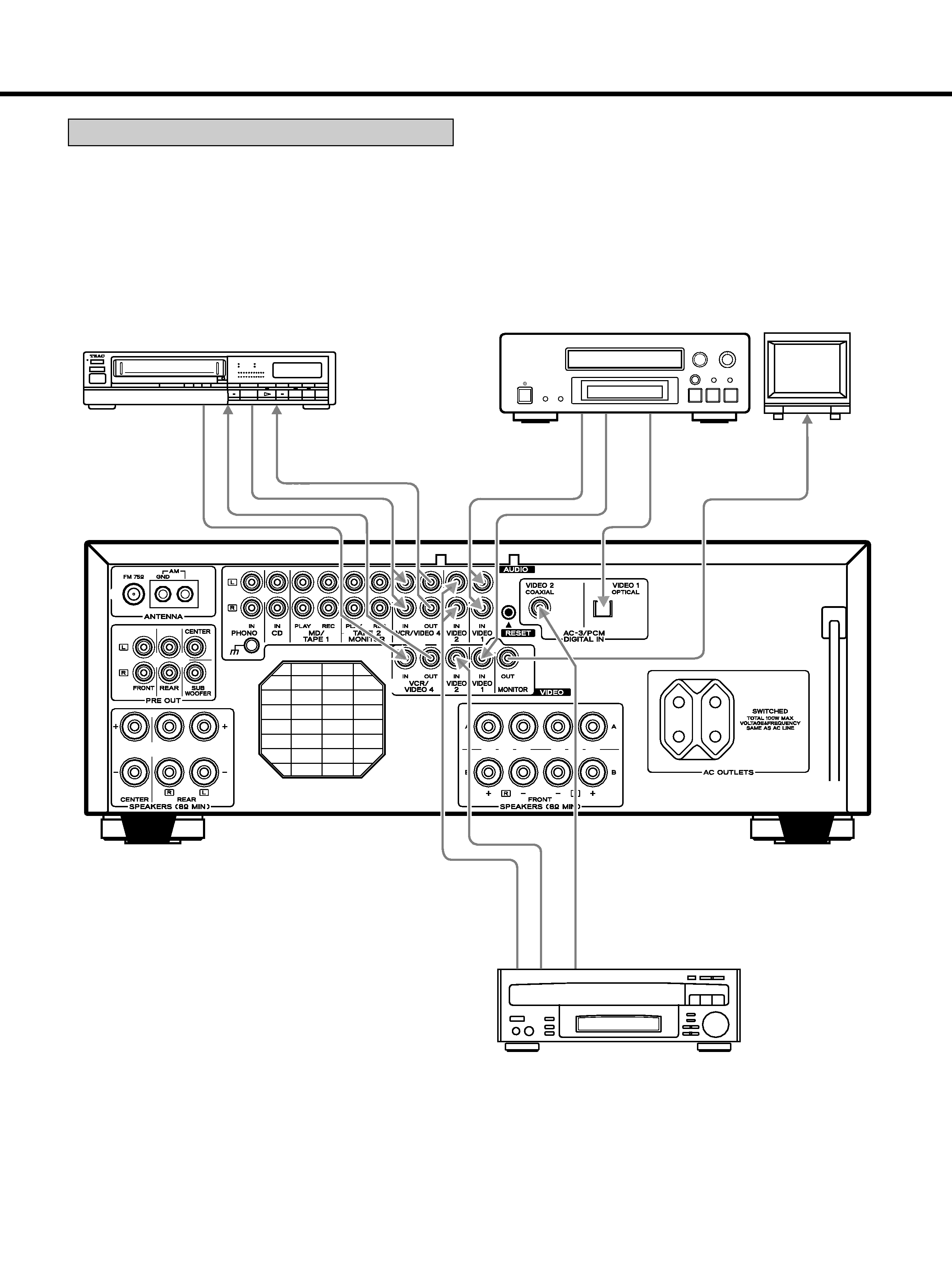
Connecting Video Equipment
AUDIO signal jacks
... Connect the video deck (VCR) LINE output (AUDIO
OUT) jacks to the IN (VCR/VIDEO 4) jacks, and the
video deck (VCR) LINE input (AUDIO IN) jacks to the
OUT (VCR/VIDEO 4) jacks.
... Connect the DVD player or LD player AUDIO OUTPUT
jacks to the VIDEO 1/2 IN jacks.
VIDEO signal jacks
... Connect the TV monitor VIDEO IN jack to the MONI-
TOR OUT jack.
... Connect the video deck (VCR) VIDEO OUT (VIDEO)
jack to the IN (VCR/VIDEO 4) jack.
Connect the video deck (VCR) VIDEO IN jacks to the
OUT (VCR/VIDEO 4) jack.
... Connect the DVD player or LD player VIDEO OUTPUT
jacks to the VIDEO 1/2 IN jacks.
AC-3/PCM DIGITAL IN (VIDEO 1, VIDEO 2) jacks
... If the player is provided with a DIGITAL OUTPUT jack,
connect it to the DIGITAL IN jack. (Use the optional
coaxial cord or optical fiber cable.)
... When an optical fiber cable is used for connection,
remove the caps protecting both ends of the optical
cable and the connectors.
Notes:
... When both the analog AUDIO IN (VIDEO 1/2) and
DIGITAL IN (VIDEO 1/2) of the receiver are connected,
signals input to the DIGITAL IN jack (VIDEO 1/2) have
priority.
... For better sound quality, we recommend using digital
rather than analog connections when connecting the
DVD/LD player.
VIDEO 1
DVD Player
VIDEO
OUT
AUDIO
OUT
DIGITAL
OUT
(COAXIAL)
TV Monitor
VIDEO 2
DVD or LD Player
VIDEO
OUT
(OPTICAL)
VIDEO
IN
AUDIO
OUT
AUDIO
IN
VCR / VIDEO 4
Video Deck (VCR)
DIGITAL
OUT
VIDEO
OUT
VIDEO
IN
AUDIO
OUT
5
ENGLISH
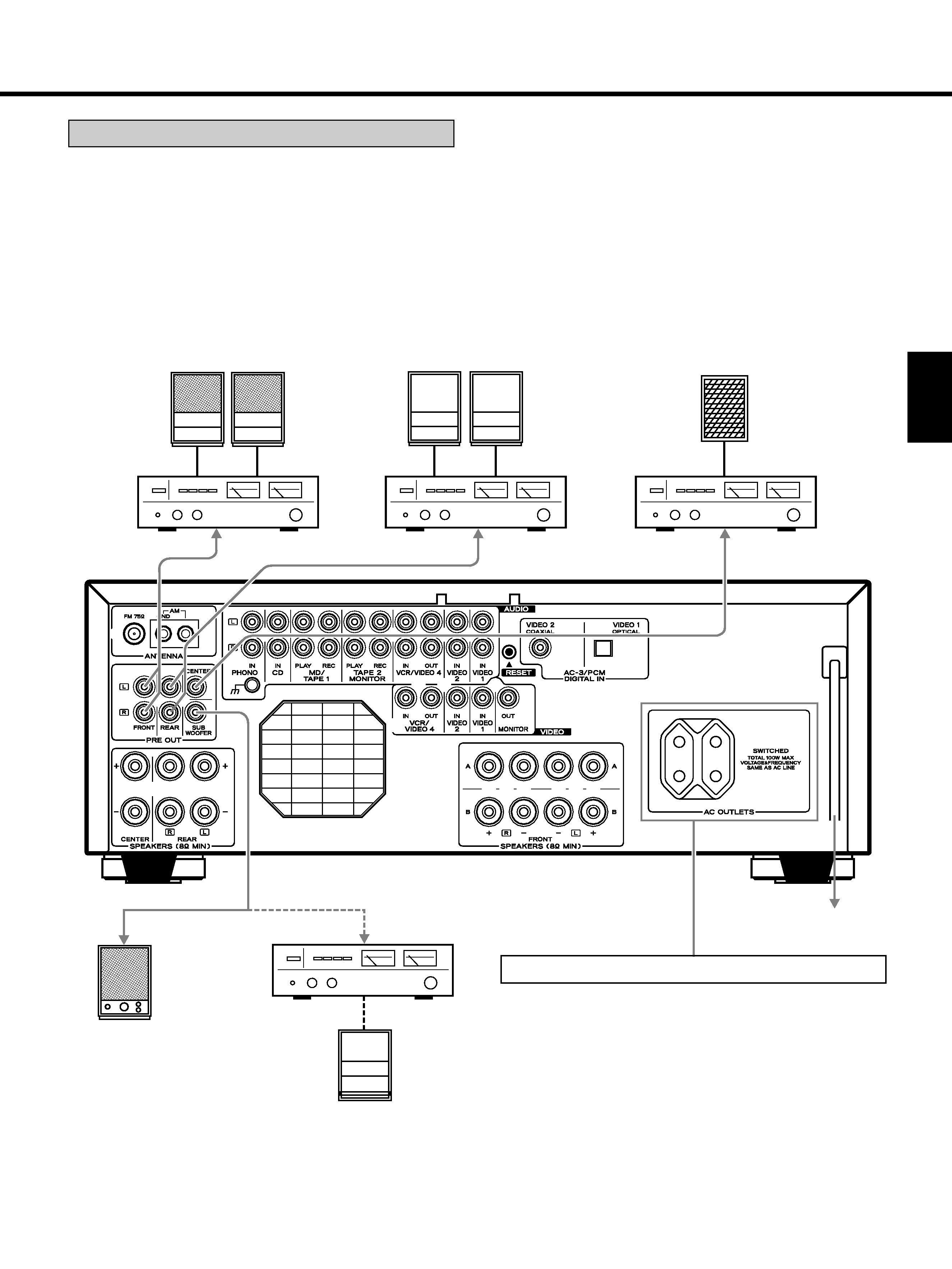
Notes:
... If a speaker is connected directly to the PRE OUT jack
without an amplifier connected, no sound comes
from the speaker.
... When the STEREO mode is selected, no signal is out-
put from the SUBWOOFER PRE OUT jack.
Connecting the PRE OUT jacks
By connecting an external power amplifier, you can
increase the number of available outputs and the output
levels. When an external power amplifier is connected,
be sure to connect the speakers for each amplifier.
Since subwoofer signals are not amplified, use a sub-
woofer with a built-in amplifier or connect it to the ampli-
fier connected to this unit.
SWITCHED:
These outlets are only active when the receiver is
turned on.
Caution:
Make sure that the total power consumption of all
equipment connected to the outlets on the receiver
does not exceed 100 watts.
Center Speaker
Subwoofer without
amplifier
Subwoofer with
built-in amplifier
Power Amplifier
Power Amplifier
Power Amplifier
Power Amplifier
or
Front Speaker
Right
Left
Rear Speaker
Right
Left
AC OUTLETS
To AC outlet