a-bx10mkTM
`
Thanks for buying a TEAC. Read this manual carefully to get the best
performance from this unit.
Nous vous remercions pour l'achat d'un appareil TEAC.
Lire ce manuel avec attention pour obtenir les meilleures performances
possibles de cet appareil.
Vielen Dank für den Kauf dieses TEAC-Geräts.
Bitte lesen Sie diese Anleitung sorgfältig durch, um die Leistungsfähigkeit
dieses Geräts optimal nutzen zu können.
Grazie per aver acquistato un prodotto TEAC.
Leggere attentamente questo manuale per ottenere le migliori prestazioni
da questo apparecchio.
Enhorabuena por la adquisición de un TEAC.
Lea detenidamente este manual a fin de obtener el mejor rendimiento de
esta unidad.
Dank u voor de aanschaf van een TEAC.
Lees deze gebruiksaanwijzing aandachtig door teneinde de beste prestaties
van dit toestel te verkrijgen.
Integrated Stereo Amplifier
OWNER'S MANUAL ..................................3
MANUEL DU PROPRIETAIRE...................6
BEDIENUNGSANLEITUNG........................9
MANUALE DI ISTRUZIONI .....................12
MANUAL DEL USUARIO ........................15
GEBRUIKSAANWIJZING.........................18
9A07108800
This appliance has a serial number located
on the rear panel. Please record the model
number and serial number and retain them
for your records.
Model number
Serial number
WARNING: TO PREVENT FIRE OR SHOCK
HAZARD, DO NOT EXPOSE THIS
APPLIANCE TO RAIN OR MOISTURE.
The exclamation point within an equilateral triangle is intended to alert the user to the presence of important
operating and maintenance (servicing) instructions in the literature accompanying the appliance.
The lightning flash with arrowhead symbol, within an equilateral triangle, is intended to alert
the user to the presence of uninsulated "dangerous voltage" within the product's enclosure
that may be of sufficient magnitude to constitute a risk of electric shock to persons.
CAUTION: TO REDUCE THE RISK OF ELECTRIC SHOCK, DO NOT REMOVE COVER
(OR BACK). NO USER-SERVICEABLE PARTS INSIDE. REFER SERVICING TO QUALIFIED
SERVICE PERSONNEL.
Ü
ÿ
Y
2
IMPORTANT SAFETY INSTRUCTIONS
CAUTION:
O Read all of these Instructions.
O Save these Instructions for later use.
O Follow all Warnings and Instructions marked on the audio
equipment.
1) Read Instructions -- All the safety and operating instructions should
be read before the product is operated.
2) Retain Instructions -- The safety and operating instructions should
be retained for future reference.
3) Heed Warnings -- All warnings on the product and in the operating
instructions should be adhered to.
4) Follow Instructions -- All operating and use instructions should be
followed.
5) Cleaning -- Unplug this product from the wall outlet before cleaning.
Do not use liquid cleaners or aerosol cleaners. Use a damp cloth for
cleaning.
6) Attachments -- Do not use attachments not recommended by the
product manufacturer as they may cause hazards.
7) Water and Moisture -- Do not use this product near water _ for
example, near a bath tub, wash bowl, kitchen sink, or laundry tub; in a
wet basement; or near a swimming pool; and the like.
8) Accessories -- Do not place this product on an unstable cart, stand,
tripod, bracket, or table. The product may fall, causing serious injury to a
child or adult, and serious damage to the product. Use only with a cart,
stand, tripod, bracket, or table recommended by the manufacturer, or
sold with the product. Any mounting of the product should follow the
manufacturer's instructions, and should use a mounting accessory
recommended by the manufacturer.
9) A product and cart combination should be moved with care. Quick
stops, excessive force, and uneven surfaces may cause the product and
cart combination to overturn.
10) Ventilation -- Slots and openings in the cabinet are provided for
ventilation and to ensure reliable operation of the product and to protect
it from overheating, and these openings must not be blocked or covered.
The openings should never be blocked by placing the product on a bed,
sofa, rug, or other similar surface. This product should not be placed in a
built-in installation such as a bookcase or rack unless proper ventilation
is provided or the manufacturer's instructions have been adhered to.
11) Power Sources -- This product should be operated only from the
type of power source indicated on the marking label. If you are not sure
of the type of power supply to your home, consult your product dealer or
local power company. For products intended to operate from battery
power, or other sources, refer to the operating instructions.
12) Grounding or Polarization -- This product may be equipped with a
polarized alternating-current line plug (a plug having one blade wider
than the other). This plug will fit into the power outlet only one way. This
is a safety feature. If you are unable to insert the plug fully into the outlet,
try reversing the plug. If the plug should still fail to fit, contact your
electrician to replace your obsolete outlet. Do not defeat the safety
purpose of the polarized plug.
13) Power-Cord Protection -- Power-supply cords should be routed so
that they are not likely to be walked on or pinched by items placed upon
or against them, paying particular attention to cords at plugs,
convenience receptacles, and the point where they exit from the product.
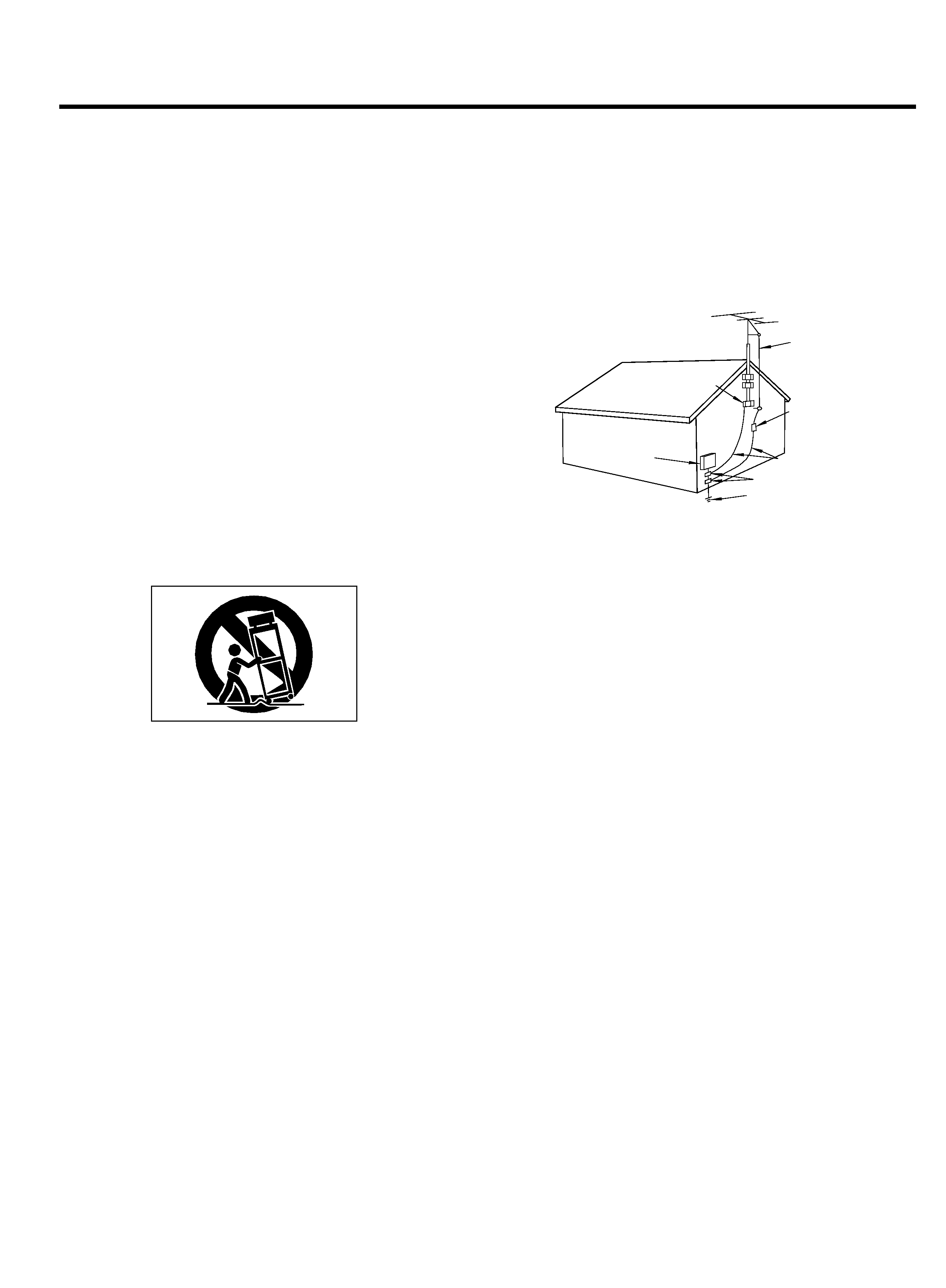
14) Outdoor Antenna Grounding -- If an outside antenna or cable
system is connected to the product, be sure the antenna or cable system
is grounded so as to provide some protection against voltage surges and
built-up static charges. Article 810 of the National Electrical Code,
ANSI/NFPA 70, provides information with regard to proper grounding of
the mast and supporting structure, grounding of the lead-in wire to an
antenna discharge unit, size of grounding conductors, location of
antenna-discharge unit, connection to grounding electrodes, and
requirements for the grounding electrode.
"Note to CATV system installer:
This reminder is provided to call the CATV system installer's attention to
Section 820-40 of the NEC which provides guidelines for proper
grounding and, in particular, specifies that the cable ground shall be
connected to the grounding system of the building, as close to the point
of cable entry as practical.
ANTENNA
LEAD IN
WIRE
ANTENNA
DISCHARGE UNIT
(NEC SECTION 810-20)
G
ROUNDING CONDUCTORS
(NEC SECTION 810-21)
GROUND CLAMPS
POWER SERVICE GROUNDING
ELECTRODE SYSTEM
(NEC ART 250. PART H)
NEC - NATIONAL ELECTRICAL CODE
ELECTRIC
SERVICE
EQUIPMENT
Example of Antenna Grounding as per
National Electrical Code, ANSI/NFPA 70
GROUND
CLAMP
15) Lightning -- For added protection for this product during a lightning
storm, or when it is left unattended and unused for long periods of time,
unplug it from the wall outlet and disconnect the antenna or cable
system. This will prevent damage to the product due to lightning and
power-line surges.
16) Power Lines -- An outside antenna system should not be located in
the vicinity of overhead power lines or other electric light or power
circuits, or where it can fall into such power lines or circuits. When
installing an outside antenna system, extreme care should be taken to
keep from touching such power lines or circuits as contact with them
might be fatal.
17) Overloading -- Do not overload wall outlets, extension cords, or
integral convenience receptacles as this can result in risk of fire or
electric shock.
18) Object and Liquid Entry -- Never push objects of any kind into this
product through openings as they may touch dangerous voltage points
or short-out parts that could result in a fire or electric shock. Never spill
liquid of any kind on the product.
19) Servicing -- Do not attempt to service this product yourself as
opening or removing covers may expose you to dangerous voltage or
other hazards. Refer all servicing to qualified service personnel.
20) Damage Requiring Service -- Unplug this product from the wall
outlet and refer servicing to qualified service personnel under the
following conditions:
a) when the power-supply cord or plug is damaged.
b) if liquid has been spilled, or objects have fallen into the product.
c) if the product has been exposed to rain or water.
d) if the product does not operate normally by following the operating
instructions. Adjust only those controls that are covered by the operating
instructions as an improper adjustment of other controls may result in
damage and will often require extensive work by a qualified technician to
restore the product to its normal operation.
e) if the product has been dropped or damaged in any way.
f ) when the product exhibits a distinct change in performance _ this
indicates a need for service.
21) Replacement Parts -- When replacement parts are required, be
sure the service technician has used replacement parts specified by the
manufacturer or have the same characteristics as the original part.
Unauthorized substitutions may result in fire, electric shock, or other
hazards.
22) Safety Check -- Upon completion of any service or repairs to this
product, ask the service technician to perform safety checks to
determine that the product is in proper operating condition.
23) Wall or Ceiling Mounting -- The product should be mounted to a
wall or ceiling only as recommended by the manufacturer.
24) Heat -- The product should be situated away from heat sources
such as radiators, heat registers, stoves, or other products (including
amplifiers) that produce heat.
3
Before Use
Read This Before Operating
IMPORTANT (for U.K. Customers)
DO NOT cut off the mains plug from this
equipment. If the plug fitted is not
suitable for the power points in your
home or the cable is too short to reach
a
power
point,
then
obtain
an
appropriate safety approved extension
lead or consult your dealer.
If nonetheless the mains plug is cut off,
remove the fuse and dispose of
the
plug immediately, to avoid a possible
shock
hazard
by
inadvertent
connection to the mains supply.
If this product is not provided with a
mains plug, or one has to be fitted, then
follow the instructions given below:
IMPORTANT. The wires in this mains
lead are coloured in accordance with
the following code:
GREEN-AND-YELLOW: EARTH
BLUE:
NEUTRAL
BROWN:
LIVE
WARNING: This apparatus must be
earthed.
As the colours of the wires in the mains
lead of this apparatus may not
correspond with the coloured markings
identifying the terminals in your plug
proceed as follows.
The wire which is coloured GREEN-
and-YELLOW must be connected to the
terminal in the plug which is marked by
the letter E or by the safety
earth
symbol © or coloured GREEN or
GREEN-and-YELLOW.
The wire which is coloured BLUE must
be connected to the terminal which is
marked with the letter N or coloured
BLACK.
The wire which is coloured BROWN
must be connected to the terminal
which is marked with the letter L or
coloured RED.
When replacing the fuse only a
correctly rated approved type should
be used and be sure to re-fit the fuse
cover.
IF
IN
DOUBT
--
CONSULT
A
COMPETENT ELECTRICIAN.
Place the amplifier on a hard flat
surface.
The ventilation holes should not be
covered. Make sure there is at least 20
cm (8 inches) of space above and at
least 5 cm (2 inches) of space besides
the amplifier. Do not place CD player or
other equipment on top of the amplifier.
Avoid placing it in direct sunlight or
close to a source of heat. Also avoid
locations subject to vibrations and
excessive dust, heat, cold or moisture.
Do not open the cabinet, as this might
result in circuitry damage or electrical
shock.
When removing the power plug from the
wall outlet, always pull directly on the
plug; never yank the cord.
Do not attempt to clean the unit with
chemical solvents, as this might damage
the finish. Use a clean, dry cloth.
Keep this manual in a safe place for
future reference.
Notes on Power Sources
Plug the AC power cord into an AC wall
receptacle. The correct voltage for
operating your unit is printed on the rear
panel.
Main POWER Switch
The main POWER switch is located on
the rear of the unit.
Press the ON side of this rocker (seesaw)
switch to turn power ON (standby position);
press the OFF side to turn power off.
Whenever the power is ON, the indicator on
the front panel glows red.
Note: Leave this main power switch ON at
all times.
AC IN Socket
Plug the provided AC power cord into this
socket.
Fuse Holder
After replacing fuses, be sure to close the
fuse compartment until it clicks.
When operating the remote control unit,
point it towards the remote sensor on the
front panel of the unit.
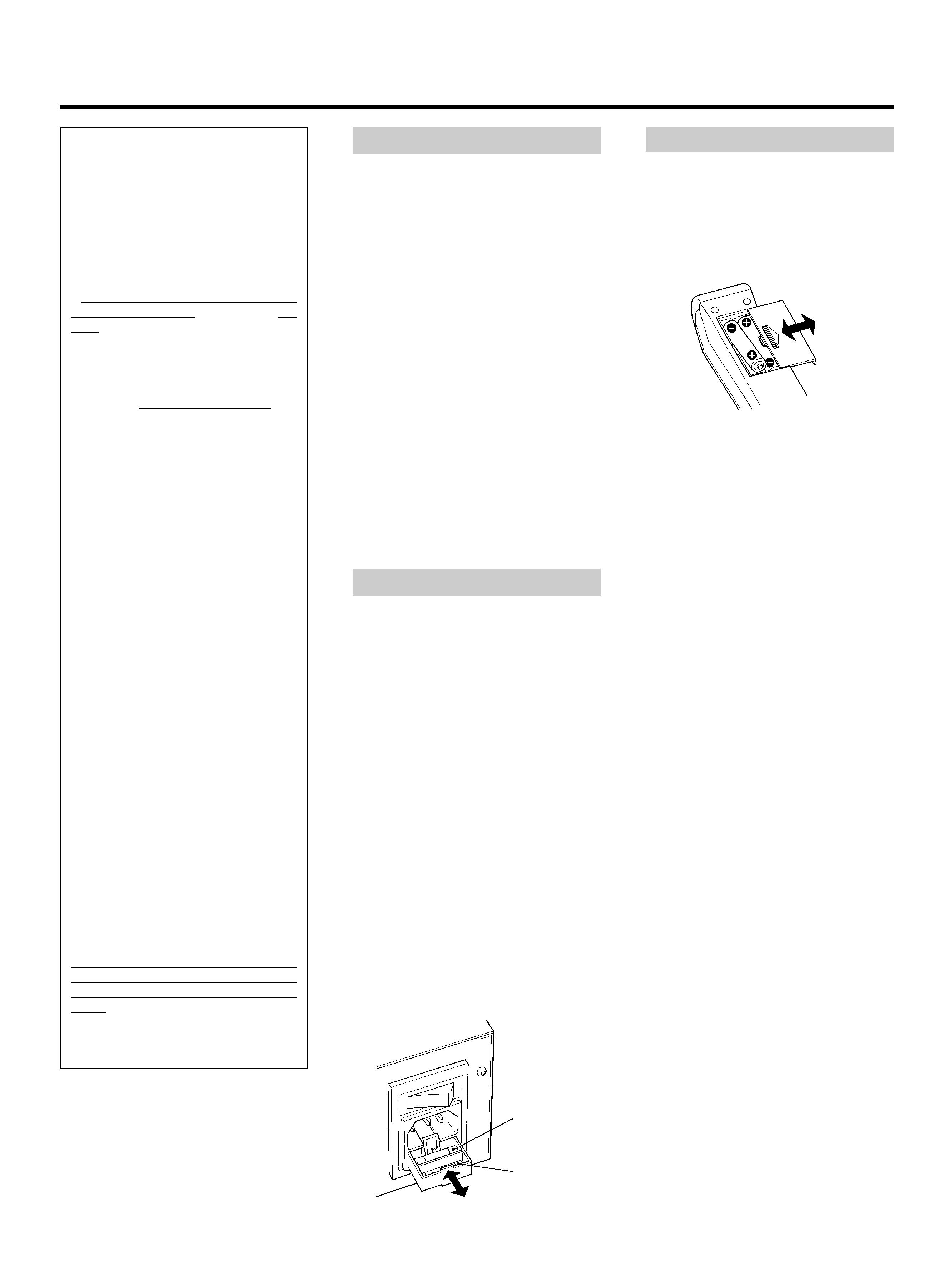
Battery Installation
Remote Control Unit
1. Remove
the
battery
compartment
cover.
2. Insert two "AAA" (R03, UM-4) dry
batteries.
Make sure that the batteries are
inserted with their positive
± and
negative
-- poles positioned correctly.
3. Close the cover until it clicks.
Battery Replacement.
If you notice that the distance between
the remote control unit and the player for
correct operation becomes shorter, it
indicates that the batteries are exhaust-
ed. In this case replace the batteries with
new ones.
Precautions concerning batteries
... Be sure to insert the batteries with
correct positive
± and negative --
polarities.
... Use batteries of the same type. Never
use
different
types
of
batteries
together.
... Rechargeable and non-rechargeable
batteries can be used. Refer to the
precautions on their labels.
... When the remote control unit is not to
be used for a long time (more than a
month), remove the batteries from the
remote control unit to prevent them
from leaking. If they leak, wipe away
the
liquid
inside
the
battery
compartment and replace the batteries
with new ones.
... Do not heat or disassemble batteries
and never dispose of old batteries by
throwing them in fire.
Main fuse
Spare fuse
4
3
Front Panel
3
5
7
89
1
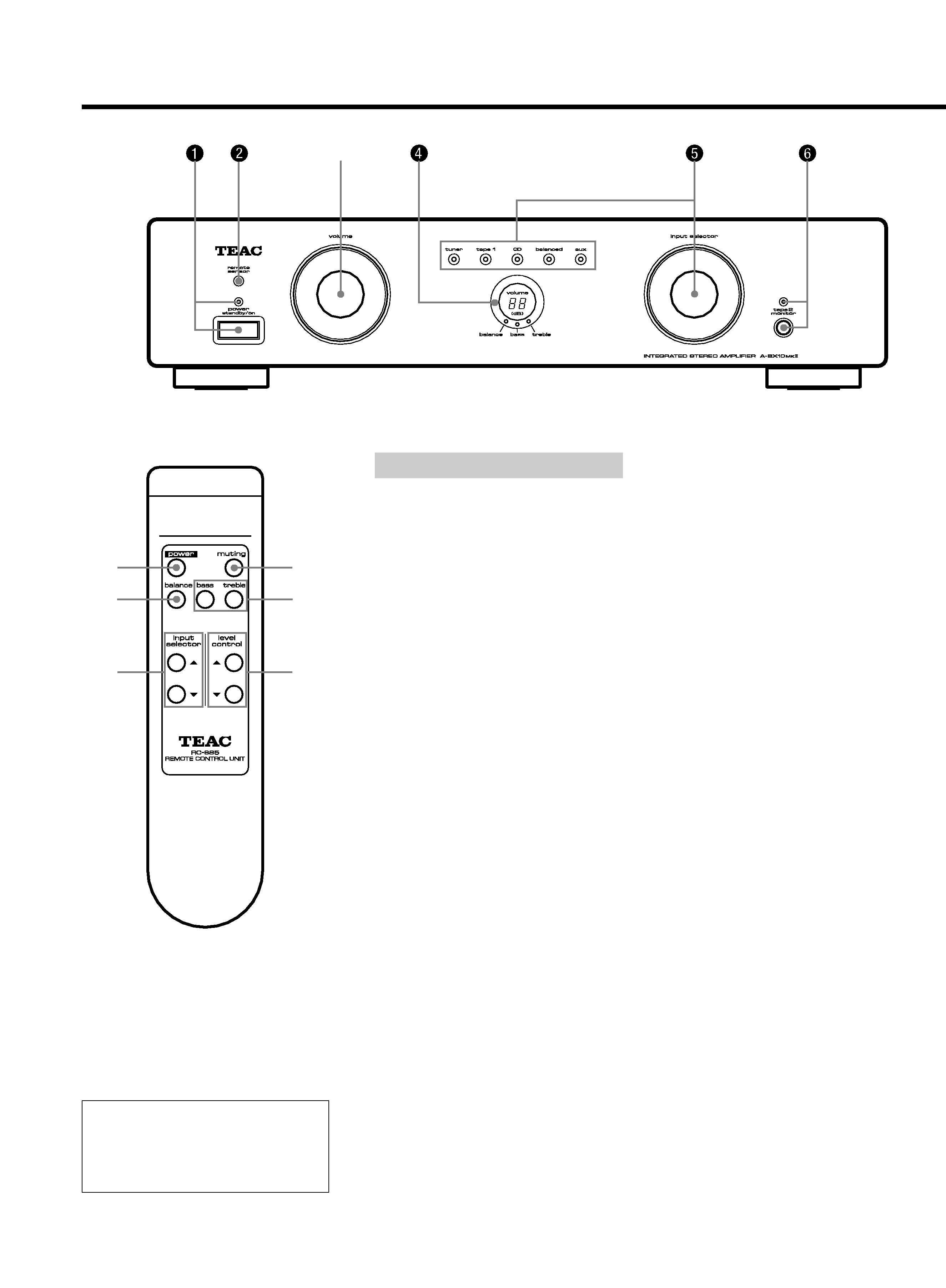
Front Panel
1 power switch
When the main power switch on the rear
panel is ON:
Turn the front power switch to ON.
Turn it again to the Standby Position to
switch power OFF, and the LED indicator
glows red.
2 remote sensor
3 volume control
This control is used to adjust signal output
levels to the speakers.
Use the level control (/¥) buttons to
adjust the volume. The volume can be
adjusted in 1 dB units from 0 dB (minimum)
to 79 dB (maximum).
4 volume level display
The current level setting is shown on the
display.
5 input selector & indicators
Turn the selector to choose the input
source to be played (tuner, tape 1, CD,
balanced, and aux).
The input source indicator will light.
6 tape 2 monitor switch & indicator
source:For
reproduction
of
sound
from a source selected using the
input selector. The LED indicator
will not light.
tape:
For reproduction of sound using
tape 2 monitor. The LED indicator
will light.
Phono Play
The PA-B10 plug-in "balanced MM/MC
preamplifier"
board
is
optionally
available so you can connect a
turntable to this unit.
Certain buttons on the remote control unit
and on the front panel of the amplifier have
the same or similar functions and have the
same reference numbers.
The power is turned on/off (standby) by
pressing the power button on the
remote control unit in standby mode.
7 muting button
(on the remote control unit)
Press this to mute (0 dB) the sound from the
speakers when answering the telephone,
etc. To restore the original volume, press
the input selector buttons or level control
(/¥) buttons. While muting is engaged,
the volume level display shows 0 dB.
8 balance control button
This button is used for adjusting the
balance of the volume level between the
left and right channels.
Press the balance button (the balance LED
indicator will light.), then press the level
control (/¥) buttons.
The level setting is shown on the display.
The balance level can be adjusted in 1 dB
units from 6 dB to 6 dB.
9 Tone (bass/treble) controls
These two tone controls bass and treble
can be used to obtain a "flat" frequency
response or a tone which suits your
individual listening preference. The bass
control adjusts low frequencies and the
treble control adjusts the high frequencies.
Press the bass (or treble) button (the bass
or treble LED indicator will light.), then
press the level control (/¥) buttons.
It is possible to adjust the bass ( or treble)
two steps down (1 or 2) or two steps up
(1 or 2).
If levels are not adjusted within 10
seconds, the LED indicator will turn off,
and volume can be adjusted again.
Features and Controls
Remote Control Unit
5
0
ey
q
0
w
rt
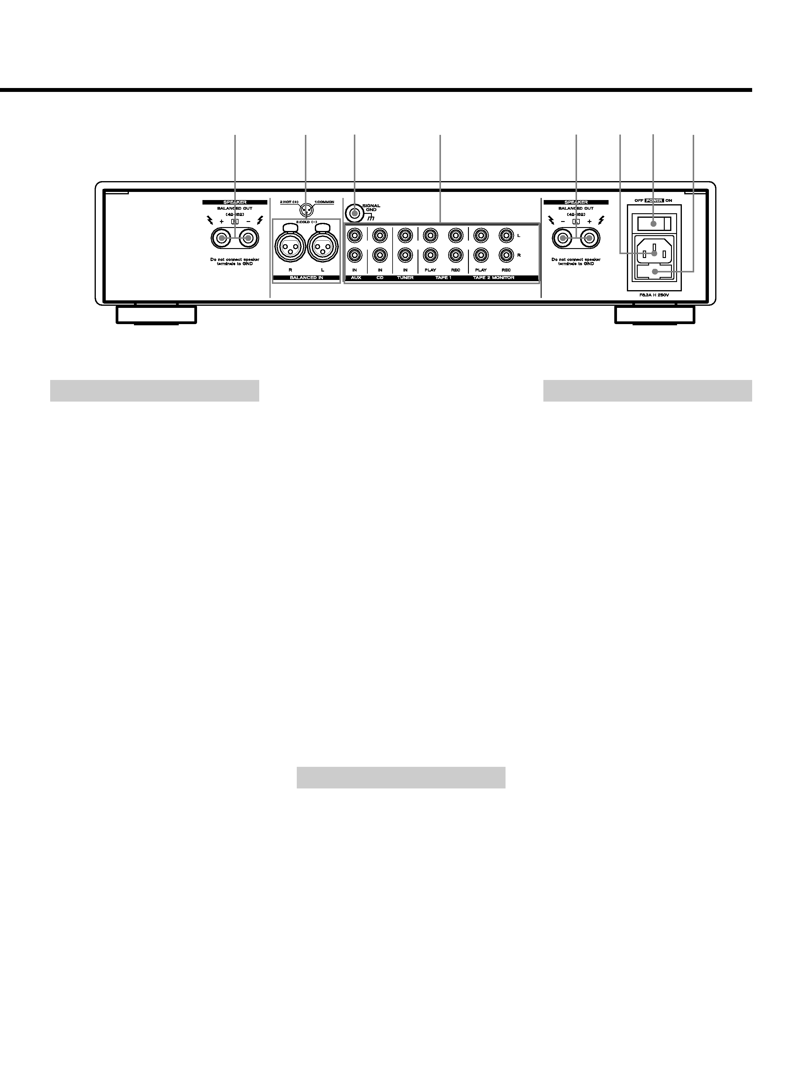
Rear Panel
0Speaker Terminals
Connect left loudspeaker to "SPEAKER L",
and right loudspeaker to "SPEAKER R".
Be sure that the loudspeakers are
connected in phase.
Caution: Short-circuiting of either of the
loudspeaker terminals to the cabinet,
ground or signal cables can damage the
amplifier.
Short-circuit
between
the
loudspeaker terminals will blow the fuses.
Always turn off the amplifier when
connecting or disconnecting loudspeaker
cables or signal cables.
Caution:
The
loudspeaker
output
is
balanced. Do not connect any equipment
with unbalanced input (e.g. spectrum
analyzers
and
some
electrostatic
loudspeakers).
q Balanced Input Connector
The balanced input is connected with XLR
plugs
in
accordance
with
IEC
specifications.
PIN 1: GND
PIN 2: +
PIN 3:
w GND Terminal
Connect the ground lead of the turntable to
this terminal.
e Audio Signal Jacks
AUX Input Jacks
Connect the audio output jacks of the
VCR to these jacks.
CD Input Jacks
Connect the output (LINE OUT) jacks of
the CD player to these jacks.
TUNER Input Jacks
Connect the output jacks of the tuner to
these jacks.
TAPE 1 PLAY/REC Jacks
Connect the output (LINE OUT) jacks of
the tape deck to the PLAY jacks and
connect the input (LINE IN) jacks of the
deck to the REC jacks.
TAPE 2 MONITOR PLAY/REC Jacks
These jacks are used for connection of a
second tape deck. Connect the output
(LINE OUT) jacks of the tape deck to the
PLAY jacks and connect the input (LINE
IN) jacks of the deck to the REC jacks.
r AC IN Socket (See page 3.)
t Main POWER Switch (See page 3.)
Press the ON side of this rocker (seesaw)
switch to turn power ON (standby position).
Note: Leave this main power switch ON at
all times.
y Fuse Holder (See page 3.)
Tape Dubbing
You can dub from the deck connected to
TAPE 1 jacks to the deck connected to TAPE
2 jacks. Dubbing from TAPE 2 deck to TAPE
1 deck is not possible.
1. Set the playback deck (TAPE 1) to the
playback mode, and the recording deck
(TAPE 2 MONITOR) to the record mode.
Adjust recording level accordingly.
(Refer to the owner's manuals of the
decks.)
2. Set the input selector to the tape 1
position and set the tape 2 monitor
switch to source.
Specifications
Continuous Power Output (RMS):
100W + 100W
(20 - 20,000 Hz, 8 ohms)
160W + 160W
(20 - 20,000 Hz, 4 ohms)
Dynamic Power Output (EIA):
120W + 120W (8 ohms)
220W + 220W (4 ohms)
Total Harmonic Distortion:
(Continuous rated output power)
0.04% (20 - 20,000 Hz, 6dB, 8 ohms)
0.06% (20 - 20,000 Hz, 6dB, 4 ohms)
Input Sensitivity/Impedance:
CD, TUNER, AUX, TAPE;
300 mV/ 20 k ohms
BALANCED (XLR); 600mV/10 k ohms
Output Level/Impedance:
TAPE 1, TAPE 2; 300 mV/100 ohms
Signal-to-Noise Ratio (IHF-A):
CD, TUNER, AUX, TAPE; 104 dBA
Frequency Response:
CD, TUNER, AUX, TAPE, BALANCED;
20 - 20,000 Hz, +0 / 0.8 dB
Power Requirements/Power Consumption:
120 V AC, 60 Hz, 5 A (U.S.A./Canada
Model/General Export Model)
220 V AC, 50/60 Hz, 500 W (Korea)
230 V AC, 50 Hz, 500 W (Europe/ UK /
General Export Model)
Dimensions (W x H x D):
442 x 103 x 383 mm
Weight (net): 12.0 kg
Standard Accessories:
Remote Control Unit (RC-685) x 1,
AC cord x 1
Improvements may result in features and
specifications being changed without
notice.
Rear Panel
*Turn off all components before making connections.