SERVICE MANUAL
PERSONAL AUDIO SYSTEM
US Model
Canadian Model
E Model
Australian Model
ZS-YN7
Ver. 1.1 2005.09
9-877-962-02
2005I05-1
© 2005.09
Sony Corporation
Personal Audio Group
Published by Sony Engineering Corporation
Model Name Using Similar Mechanism
NEW
Optical Pick-up Block Name
KSM-213RAP
Optical Pick-up Name
KSS-213R
SPECIFICATIONS
US and foreign patents licensed from Dolby Laboratories.
AUDIO POWER SPECIFICATIONS
POWER OUTPUT AND TOTAL HARMONIC
DISTORTION
With 3.2-ohm loads, both channels driven from
100 - 10,000 Hz; rated 1.7 W per channel-
minimum RMS power, with no more than 10 %
total harmonic distortion in AC operation.
Other Specifications
CD player section
System
Compact disc digital audio system
Laser diode properties
Material: GaAlAs
Wave length: 780 nm
Emission duration: Continuous
Laser output: Less than 44.6
µW
(This output is the value measured at a distance of about
200 mm from the objective lens surface on the optical
pick-up block with 7 mm aperture.)
Spindle speed
400 r/min (rpm) to 1 000 r/min (rpm) (CLV)
Number of channels
2
Frequency response
20 - 20 000 Hz +0/1 dB
Wow and flutter
Below measurable limit
Radio section
Frequency range
FM: 87.5 - 108 MHz
AM: 531 - 1 611 kHz (9 kHz step)
Antennas
FM: Telescopic antenna
AM: Built-in ferrite bar antenna
General
Speaker
Full range: 8 cm (3 1/4 in.) dia.,
3.2
, cone type (2)
Output
Headphones jack (stereo minijack):
For 16 - 64
impedance headphones
Power output
2.3 W + 2.3 W (at 3.2
, 10 % harmonic
distortion)
Power requirements
For player
120 V AC, 60 Hz
9 V DC, 6 size C (R14) batteries
For remote control:
3 V DC, 2 size AAA (R03) batteries
Power consumption
16 W
Battery life
For player:
CD playback
Sony R14P: approx. 1.5 h
Sony alkaline LR14: approx. 8 h
Radio reception
Sony R14P: approx. 6 h
Sony alkaline LR14: approx. 20 h
Dimensions
Approx. 455
× 214 × 180 mm (w/h/d)
(18
× 8 1/2 × 7 1/8 inches) (incl. projecting parts)
Mass
Approx. 3.5 kg (7 lb. 11 oz) (incl. batteries)
Supplied accessories
AC power cord (1) (US, Canadian, E and Mexican models)
Remote control (1)
CD-ROM (SonicStage) (1)
SonicStage Installation/Operating Guide (1)
Design and specifications are subject to change without
notice.
(US model only)
IF
FM: 10.7 MHz
AM: 450 kHz
530 - 1 610 kHz (10 kHz step)
US, Canadian, E and Mexican models:
Korean model: 220 V AC, 60 Hz
Singapore and Australian model: 230 V AC, 50 Hz
Mains lead (1) (Singapore, Korean and Australian models)
ZS-YN7
2
TABLE OF CONTENTS
1.
SERVICING NOTES ................................................ 3
2.
GENERAL ................................................................... 5
3.
DISASSEMBLY
3-1.
Disassembly Flow ...........................................................
7
3-2.
Cabinet Rear Assy ...........................................................
8
3-3.
Cabinet (Upper) ...............................................................
8
3-4.
Shassis Section ................................................................
9
3-5.
CD Block Section ............................................................
9
3-6.
LCD Board ...................................................................... 10
4.
TEST MODE .............................................................. 11
5.
ELECTRICAL ADJUSTMENTS
TUNER Section ............................................................... 12
CD Section ...................................................................... 14
6.
DIAGRAMS
6-1.
Block Diagram CD SERVO Section ........................ 16
6-2.
Block Diagram TUNER Section .............................. 17
6-3.
Block Diagram MAIN Section ................................. 18
6-4.
Printed Wiring Board CD Board .............................. 20
6-5.
Schematic Diagram CD Board ................................. 21
6-6.
Printed Wiring Board TU Board ............................... 22
6-7.
Schematic Diagram TU Board ................................. 23
6-8.
Printed Wiring Board
MAIN Board (Component Side) ............................... 24
6-9.
Printed Wiring Board
MAIN Board (Conductor Side) ................................. 25
6-10. Schematic Diagram MAIN Board (1/2) ................... 26
6-11. Schematic Diagram MAIN Board (2/2) ................... 27
6-12. Printed Wiring Boards KEY Section ........................ 28
6-13. Printed Wiring Boards POWER Section .................. 29
6-14. Schematic Diagram KEY/POWER Section ............. 30
7.
EXPLODED VIEWS
7-1.
Cabinet Rear Section ....................................................... 42
7-2.
Cabinet Front Section ...................................................... 43
7-3.
Chassis Section ................................................................ 44
7-4.
LID CD Section ............................................................... 45
7-5.
Optical Pick-up Block Section (KSM-213RAP) ............. 46
8.
ELECTRICAL PARTS LIST ................................ 47
Notes on chip component replacement
· Never reuse a disconnected chip component.
· Notice that the minus side of a tantalum capacitor may be
damaged by heat.
Flexible Circuit Board Repairing
· Keep the temperature of the soldering iron around 270 °C
during repairing.
· Do not touch the soldering iron on the same conductor of the
circuit board (within 3 times).
· Be careful not to apply force on the conductor when soldering
or unsoldering.
SAFETY-RELATED COMPONENT WARNING!!
COMPONENTS IDENTIFIED BY MARK 0 OR DOTTED LINE
WITH MARK 0 ON THE SCHEMATIC DIAGRAMS AND IN
THE PARTS LIST ARE CRITICAL TO SAFE OPERATION.
REPLACE THESE COMPONENTS WITH SONY PARTS WHOSE
PART NUMBERS APPEAR AS SHOWN IN THIS MANUAL OR
IN SUPPLEMENTS PUBLISHED BY SONY.
About CD-Rs/CD-RWs
This player can play CD-Rs/CD-RWs
recorded in the CD-DA format*, but
playback capability may vary depending on
the quality of the disc and the condition of
the recording device.
* CD-DA is the abbreviation for Compact
Disc Digital Audio. It is a recording
standard used for Audio CDs.
CAUTION
Use of controls or adjustments or performance of procedures
other than those specified herein may result in hazardous radiation
exposure.
SAFETY CHECK-OUT
After correcting the original service problem, perform the following
safety check before releasing the set to the customer:
Check the antenna terminals, metal trim, "metallized" knobs, screws,
and all other exposed metal parts for AC leakage.
Check leakage as described below.
LEAKAGE TEST
The AC leakage from any exposed metal part to earth ground and
from all exposed metal parts to any exposed metal part having a
return to chassis, must not exceed 0.5 mA (500 microamperes.).
Leakage current can be measured by any one of three methods.
1. A commercial leakage tester, such as the Simpson 229 or RCA
WT-540A. Follow the manufacturers' instructions to use these
instruments.
2. A battery-operated AC milliammeter. The Data Precision 245
digital multimeter is suitable for this job.
3. Measuring the voltage drop across a resistor by means of a
VOM or battery-operated AC voltmeter. The "limit" indication
is 0.75 V, so analog meters must have an accurate low-voltage
scale. The Simpson 250 and Sanwa SH-63Trd are examples
of a passive VOM that is suitable. Nearly all battery operated
digital multimeters that have a 2 V AC range are suitable. (See
Fig. A)
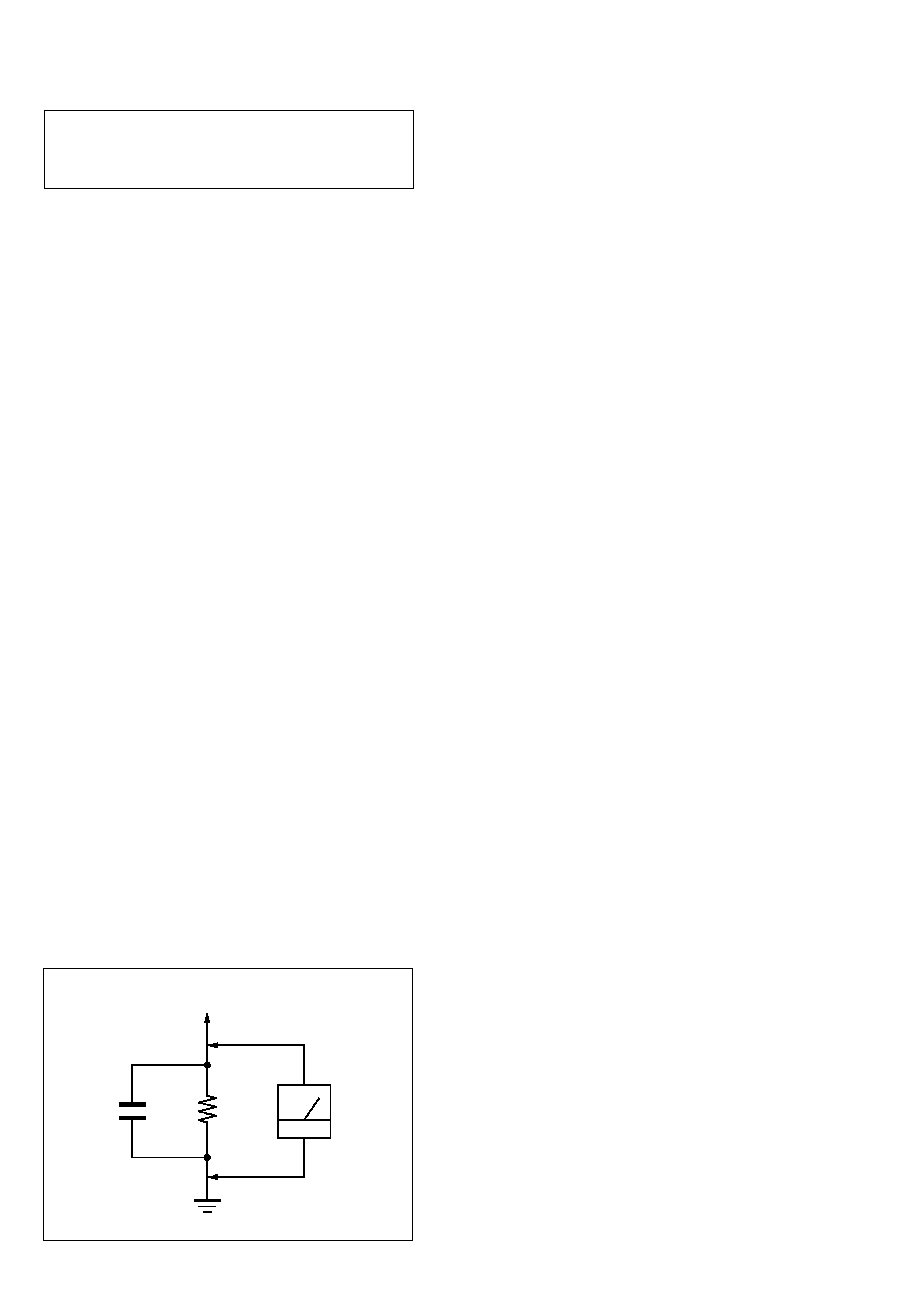
Fig. A.
Using an AC voltmeter to check AC leakage.
1.5 k
0.15
µF
AC
voltmeter
(0.75 V)
To Exposed Metal
Parts on Set
Earth Ground
ATTENTION AU COMPOSANT AYANT RAPPORT
À LA SÉCURITÉ!
LES COMPOSANTS IDENTIFIÉS PAR UNE MARQUE 0 SUR
LES DIAGRAMMES SCHÉMATIQUES ET LA LISTE DES
PIÈCES
SONT
CRITIQUES
POUR
LA
SÉCURITÉ
DE
FONCTIONNEMENT. NE REMPLACER CES COM- POSANTS
QUE PAR DES PIÈCES SONY DONT LES NUMÉROS SONT
DONNÉS DANS CE MANUEL OU DANS LES SUPPLÉMENTS
PUBLIÉS PAR SONY.
3
ZS-YN7
SECTION 1
SERVICING NOTES
The laser diode in the optical pick-up block may suffer electrostatic
break-down because of the potential difference generated by the
charged electrostatic load, etc. on clothing and the human body.
During repair, pay attention to electrostatic break-down and also
use the procedure in the printed matter which is included in the
repair parts.
The flexible board is easily damaged and should be handled with
care.
NOTES ON LASER DIODE EMISSION CHECK
The laser beam on this model is concentrated so as to be focused on
the disc reflective surface by the objective lens in the optical pick-
up block. Therefore, when checking the laser diode emission,
observe from more than 30 cm away from the objective lens.
UNLEADED SOLDER
Boards requiring use of unleaded solder are printed with the lead-
free mark (LF) indicating the solder contains no lead.
(Caution: Some printed circuit boards may not come printed with
the lead free mark due to their particular size)
: LEAD FREE MARK
Unleaded solder has the following characteristics.
· Unleaded solder melts at a temperature about 40 °C higher
than ordinary solder.
Ordinary soldering irons can be used but the iron tip has to be
applied to the solder joint for a slightly longer time.
Soldering irons using a temperature regulator should be set to
about 350
°C.
Caution: The printed pattern (copper foil) may peel away if
the heated tip is applied for too long, so be careful!
· Strong viscosity
Unleaded solder is more viscou-s (sticky, less prone to flow)
than ordinary solder so use caution not to let solder bridges
occur such as on IC pins, etc.
· Usable with ordinary solder
It is best to use only unleaded solder but unleaded solder may
also be added to ordinary solder.
NOTES ON HANDLING THE OPTICAL PICK-UP
BLOCK OR BASE UNIT
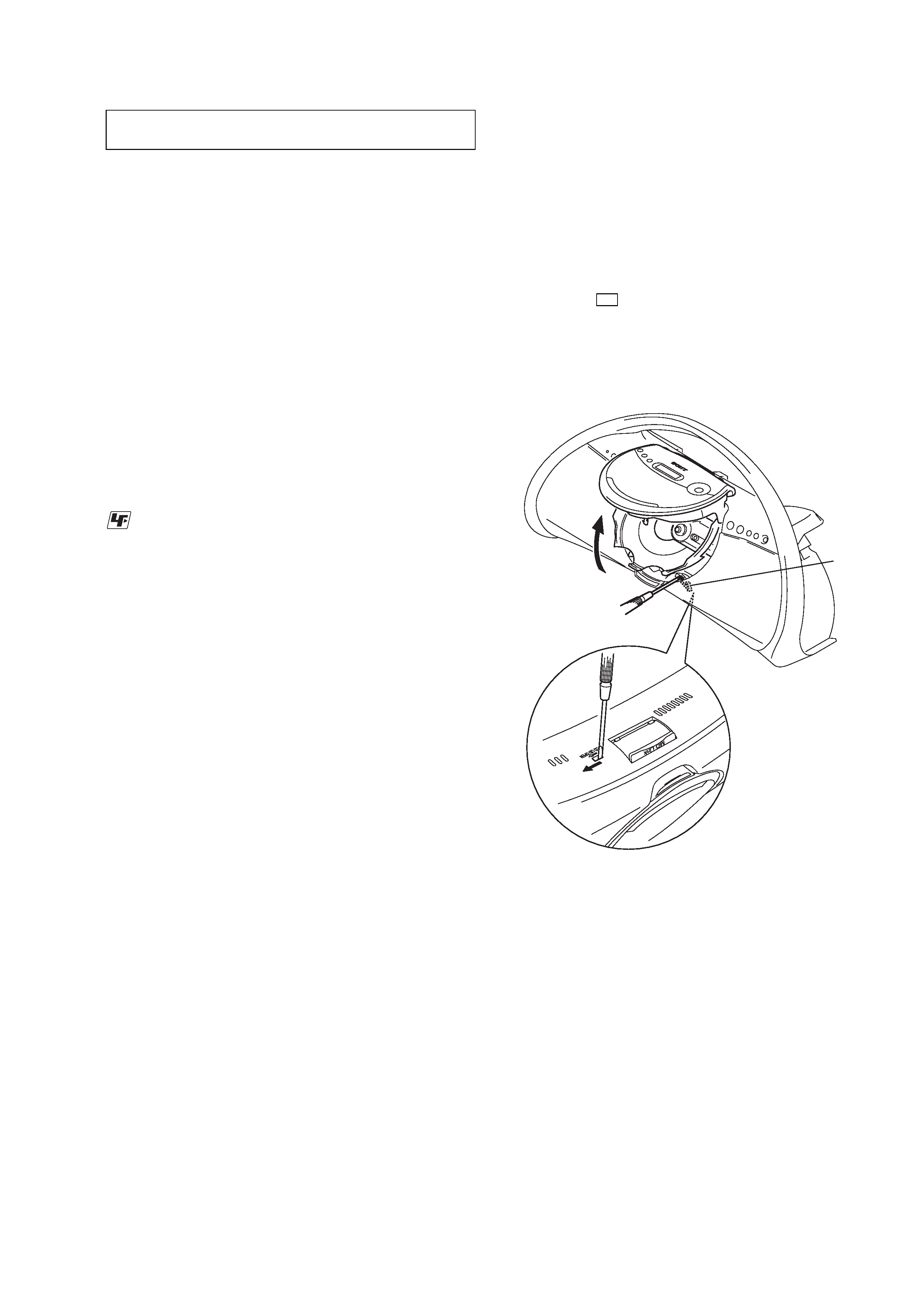
LASER DIODE AND FOCUS SEARCH OPERATION
CHECK
During normal operation of the equipment, emission of the laser
diode is prohibited unless the upper lid is closed while turning ON
the S421. (push switch type)
The following checking method for the laser diode is operable.
· Method
Emission of the laser diode is visually checked.
1. Open the upper lid.
2. Push the S421 as shown in Fig.1.
Note: Do not push the detection lever strongly, or it may be bent or damaged.
3. Press the u button.
4. Check the object lens for confirming normal emission of the
laser diode. If not emitting, there is a trouble in the automatic
power control circuit or the optical pick-up.
In this operation, the object lens will move up and down 2
times along with inward motion for the focus search.
Fig.1 Method to push the S421
2
1
S421
4
ZS-YN7
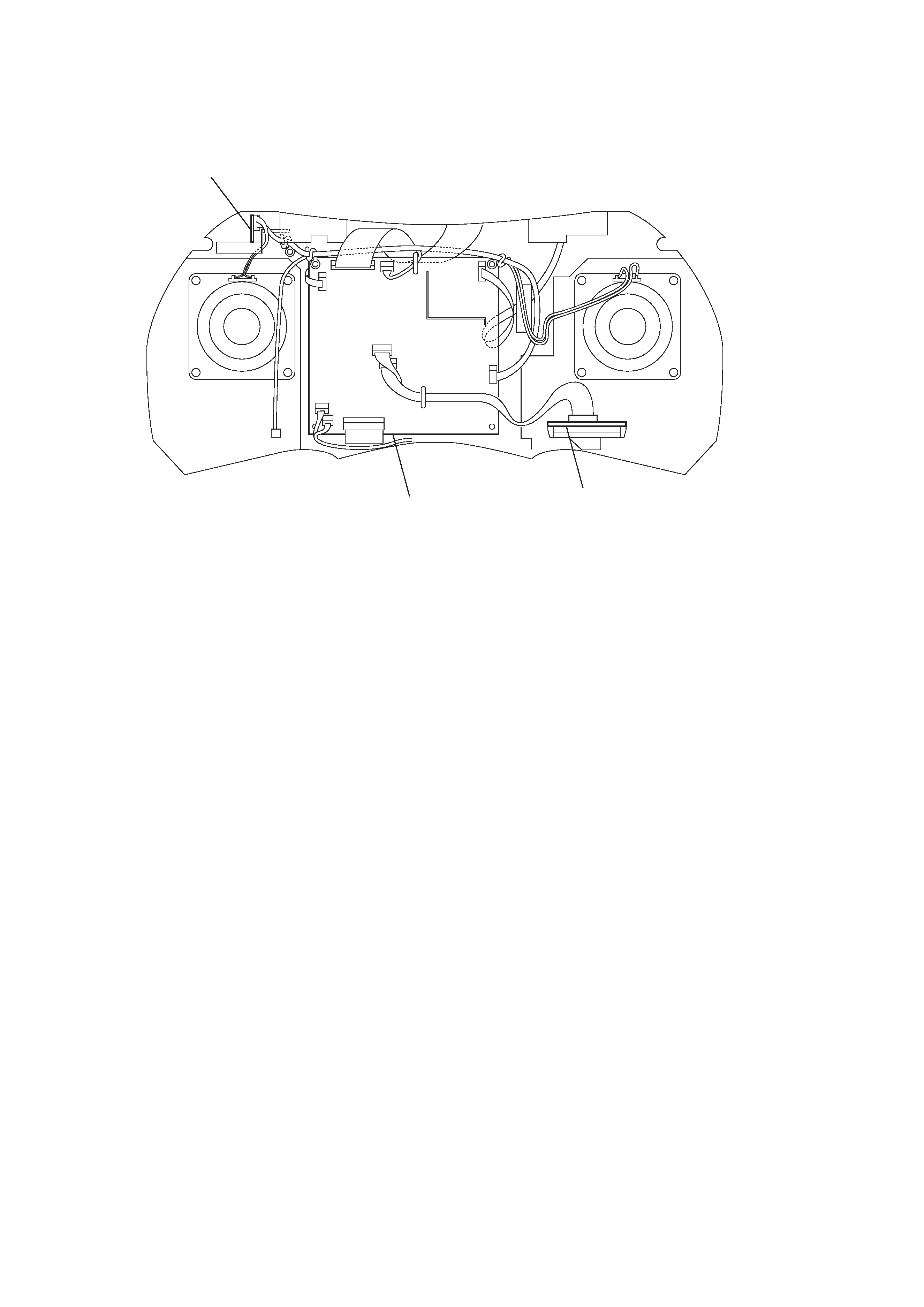
MAIN board
H/P board
TU board
HARNESS SETTING
5
ZS-YN7
SECTION 2
GENERAL
This section is extracted from
instruction manual.
6
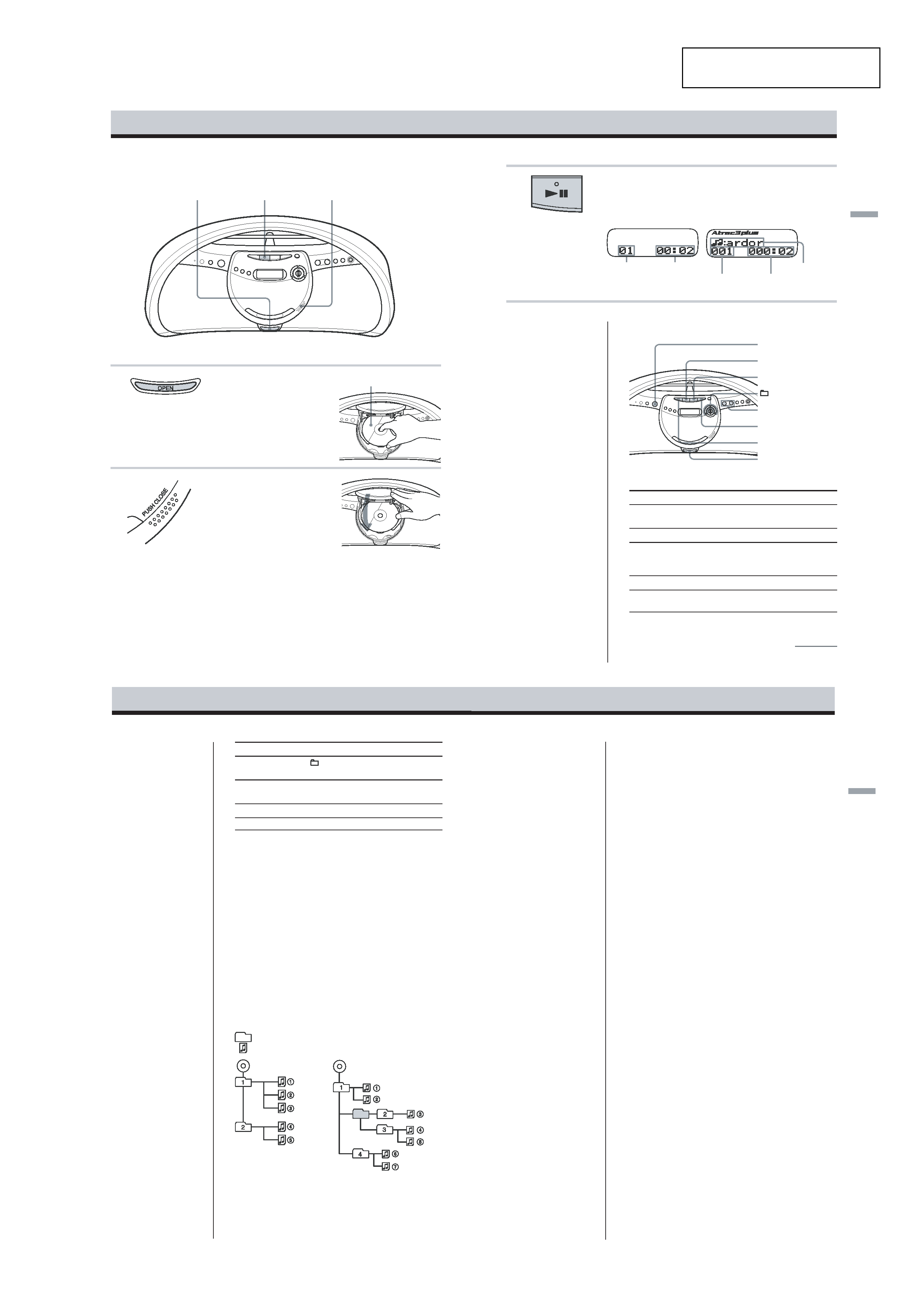
Playing a CD
Connect the supplied AC power cord
1
Press OPEN to open the CD lid
(direct power-on) and place the CD
on the CD tray.
Note
Make sure that the CD is placed properly
on the CD tray. Don't place it under the
CD tray.
2
Press PUSH CLOSE to close the CD
lid.
With the label side up
1
3
Basic Operations
2
Basic
Operations
7
Playing time
Track number
Playing time
File number
3
Press u (N on the remote).
The player plays all the tracks once.
*When playing an MP3 CD, "MP3"
appears in the display.
continued
Display
Audio CD
u
POWER
VOLUME +,
x
Use these buttons for additional operations
To
Press
adjust the volume
VOLUME +*1, (VOL +*1, on the
remote)
stop playback
x
pause playback
u*1 (X on the remote)
Press the button again to resume play after
pause.
go to the next track
>
go back to the
.
previous track
*1 The button has a tactile dot.
Tips
· To listen through
headphones, connect the
headphones to the i
(headphones) jack.
· Playback starts from the
point you last stopped
playing (Resume play).
During stop, the point to be
played is displayed.
To cancel the resume play
to start play from the
beginning of the first track,
press xin stop mode.
File name
ATRAC CD/MP3 CD*
OPEN
>
.
+,
Note
Before playing an ATRAC
CD/MP3 CD, this player
reads all file and group
information on the CD.
Depending on the file
structure, it may take more
than a minute to read them.
During this time, "Reading"
is displayed.
8
Notes
· If ATRAC3plus/ATRAC3
files and MP3 files are
recorded on the same CD,
this CD player plays the
ATRAC3plus/ATRAC3
only.
· The playback capability of
this CD player may vary
depending on the quality of
the disc and the condition of
the recording device.
· Characters that can be
displayed on this CD player
are listed below.
A to Z
a to z
0 to 9
! " # $ % & ' ( ) * + , - . / :
; < = > ? @ [ \ ] ^ _ ` { | }
~
If you use other characters
on your computer using
software such as
SonicStage, they are
displayed as "" on this CD
player.
· On a disc that has
ATRAC3plus/ATRAC3/
MP3 files, do not save files
in other formats and do not
make unneccessary groups.
ATRAC CD
To
Press
select a group*2
+ to go forward and to go
backward
select a file*2
> to go forward and . to go
backward
remove the CD
OPEN*3
turn on/off the player
POWER
*2 You can operate during play of ATRAC CDs/MP3 CDs.
*3 Once you open the CD tray, the track to start play will change to
the beginning of the first track.
The structure of ATRAC CDs/MP3 CDs
ATRAC CDs/MP3 CDs consist of "files" and "groups." A
"file" is equivalent to a "track" of an audio CD. A "group"
is a bundle of files and is equivalent to an "album."
For MP3 CDs, this CD player recognizes an MP3 folder as
a "group" so that ATRAC CDs and MP3 CDs can be
operated in the same way.
Playing order of ATRAC CDs and MP3 CDs
For ATRAC CDs, files are played in the order selected in
SonicStage.
For MP3 CDs, the playing order may differ depending on
the method used to record MP3 files on the disc. In the
following example, files are played in order of 1 to 7.
File
Group
MP3 CD
Basic
Operations
9
Notes on ATRAC CDs
·Maximum number of groups: 255
Maximum number of files: 999
·CD-Rs/CD-RWs recorded in the ATRAC3plus/ATRAC3 format
cannot be played on your computer.
Notes on MP3 CDs
·Maximum number of groups: 100
Maximum number of files: 400
Maximum directory level: 8
·A group that does not include an MP3 file is skipped.
· Be sure to add the file extension "mp3" to the file name.
However, if you add the file extension "mp3" to a file other than
an MP3 file, the player will not be able to recognize the file
properly.
· This player can play bit rates of 16 to 320 kbps, and sampling
frequencies of 32/44.1/ 48 kHz. Variable Bit Rate (VBR) file
can also be played.
· To compress a source in an MP3 file, we recommend setting the
compression parameters to "44.1 kHz," "128 kbps," and
"Constant Bit Rate."
· To record up to the maximum capacity, set the writing software
to "halting of writing."
· To record to the maximum capacity at one time up on media that
has nothing recorded on it, set the writing software to "Disc at
Once."