Ver 1.2 2001.07
With SUPPLEMENT 1
(9-923-346-82)
ZS-M7
SERVICE MANUAL
PERSONAL MINIDISC SYSTEM
SPECIFICATIONS
US Model
AEP Model
UK Model
Tourist Model
Model Name Using Similar Mechanism
NEW
MD
MD Mechanism Type
MDM-3EG
Section
Optical Pick-up Type
KMS-260A
CD
Model Name Using Similar Mechanism
NEW
Section
MD Mechanism Type
CDM-2411AAA
Optical Pick-up Type
DAX-11A
Dolby noise reduction manufactured under license from
Dolby Laboratories Licensing Corporation.
"DOLBY" and the double-D symbol
a are trademarks of
Dolby Laboratories Licensing Corporation.
Continued on page 2
CD player Section
System
Compact disc digital audio system
Laser diode properties
Material: GaAlAs
Wave length: 785 nm
Emission duration : Continuous
Laser output : Less than 44.6
µW
(This output is the value measured at a distance of about 200
mm from the objective lens surface on the optical pick-up
block with 7 mm aperture.)
Spindle speed
200 r/min (rpm) to 500 r/min (rpm) (CLV)
Number of programme positions
2
Frequency response
20 20,000 Hz +1 /2 dB
Wow and flutter
Below measurable limit
Radio section
Frequency range
US Model :
FM : 87.6 108 MHz
AM : 530 1,710 kHz
AUDIO POWER SPECIFICATIONS
POWER OUTPUT AND TOTAL HARMONIC DISTORTION
With 4-ohm loads, both channels driven from 100 10,000 Hz ; rated 7W
per channel-minimum RMS power, with no more
than 10% total harmonic distortion in AC operation (US Model).
EXCEPT US Model :
FM : 87.6 107 MHz
MW : 531 1,602 kHz
LW : 153 279 kHz
IF
FM : 10.7 MHz
MW/LW : 450 kHz
Aerials
FM : Telescopic areal
Extension areal terminal
AM : Extension areal terminals (US Model)
MW/LW : Extension areal terminals (EXCEPT US Model)
MD player section
System
Minidisc digital audio system
Disc
MiniDisc
Laser diode properties
Material: GaAlAs
Wave length: 785 nm
Emission duration : Continuous
Laser output : Less than 44.6
µW
(This output is the value measured at a distance of about 200
mm from the objective lens surface on the optical pick-up
block with 7 mm aperture.)
9-923-346-12
2001G0200-1
© 2001.7
Sony Corporation
Personal Audio Company
Shinagawa Tec Service Manual Production Group

2
Specifications ........................................................................... 1
1. SERVICE NOTE ........................................................... 3
2. GENERAL ...................................................................... 5
3. DISASSEMBLY
3-1. Cabinet (Front) ASSY, Cabinet (Rear) ASSY .......... 21
3-2. Left Key Board, Front Key Board, Top Key board,
Right Key Board, Relay Board ................................. 22
3-3. FL Board, Trans Board ............................................. 22
3-4. Tuner Board, FM ANT Board, AM ANT Board ....... 23
3-5. MD Chassis ASSY ................................................... 23
3-6. MD Block ASSY, Filter Board ................................. 24
3-7. Audio Board, HP Board, Line in Board .................... 24
3-8. Main Board, CD Block ASSY .................................. 25
3-9. Shield Case (Top), Shield Case (Bottom) ................. 25
3-10. DG Board, BD Board, MD Mechanism Deck ........ 26
3-11. Shutter ASSY .......................................................... 26
3-12. SW Board ............................................................... 27
3-13. Slider ASSY, "Head, Over Write" .......................... 27
3-14. MD Optical Pick-up Block ..................................... 28
3-15. Loading Board, "Tray ASSY, CD" ......................... 29
3-16. CD Optical Pick-up Block, Pick-up Relay Board .. 29
4. TEST MODE
4-1. Caution When Using the Test Mode ......................... 30
4-2. Test Mode Settings ................................................... 30
4-3. Releasing the Test Mode ........................................... 30
4-4. Basic Operations of the Test Mode ........................... 30
4-5. Selecting the Test Mode ............................................ 30
4-6. Functions of Other Buttons ...................................... 31
4-7 Test Mode Display ..................................................... 31
5. ADJUSTMENTS
5-1. Cautions When Checking Laser Diode Emission ..... 32
5-2. Cautions When Handling
the Optical Pick-up (KSM-260A) ............................ 32
5-3. Cautions During Adjustment .................................... 32
5-4. Creating a Continuous Recording Disk .................... 32
5-5. Temperature Compensation Offset Adjustment ........ 33
TABLE OF CONTENTS
Recording/Playback time
Maximum 74 minutes (with MDW-74)
Revolutions
400 rpm to 900 rpm (CLV)
Error correction
Advanced Cross Interleave Reed Solomon Code (ACIRC)
Sampling frequency
44.1 kHz
Cording
Adaptive Transform Acoustic Cording (ATRAC)
Modulation system
EFM (Eight-to-Fourteen Modulation)
Number of programme positions
2 stereo programme positions
Frequency response
20 20,000 Hz +1 /2 dB
Signal-to-noise ratio
Over 80 dB (during playback)
Wow and flutter
Below measurable limit
General
Speaker
Full range : 8 cm (3 in.) dia., 4ohms, cone type (2)
Inputs
LINE IN (stereo minijack) : Sensitivity 436 mV/691 mV
Outputs
Headphones jack (stereo minijack) (2) : For 32 ohms
impedance headphones
Power outputs
7 W + 7 W
Power requirements
For personal minidisc system :
US Model :120V AC, 60Hz
EXCEPT US Model :230V AC, 50Hz
For remote commander :
3V DC, 2 size AA (R6) batteries
Power consumption
30 W
Dimensions (incl. projecting parts)
Approx. 528 x 275 x 139 mm (w/h/d)
(20 7/8 x 10 7/8 x 5 1/2 inches)
Mass
approx. 6.4 kg (14 lb. 2 oz)
Supplied accessories
Remote commander (1)
AM loop aerial (1) (US Model)
MW/LW loop aerial (1) (EXCEPT US Model)
Speaker nets (2) (EXCEPT US Model)
Design and specifications are subject to change without notice.
5-6. Laser Power Adjustment ........................................... 33
5-7. Traverse Adjustment ................................................. 33
5-8. Focus Bias Adjustment ............................................. 34
5-9. Error Rate Check ...................................................... 35
5-10. Focus Bias Check ................................................... 35
5-11. Adjustment and Connection Locations ................... 35
6. DIAGRAMS
6-1. Explanation of IC Terminals ..................................... 39
6-2. Block Diagram (1) .................................................... 46
6-3. Block Diagram (2) .................................................... 49
6-4. Printed Wiring Boards Main Section ................... 55
6-5. Schematic Diagram Main Section (1/2) .............. 59
6-6. Schematic Diagram Main Section (2/2) .............. 63
6-7. Printed Wiring Boards
Tuner Section (US Model) .................................. 67
6-8. Schematic Diagram
Tuner Section (US Model) ................................... 69
6-9. Printed Wiring Boards
Tuner Section (EXCEPT US Model) ................... 72
6-10. Schematic Diagram
Tuner Section (EXCEPT US Model) .................. 74
6-11. Schematic Diagram BD Section ........................ 77
6-12. Printed Wiring Boards BD Section .................... 79
6-13. Schematic Diagram Power Section ................... 82
6-14. Printed Wiring Boards Power Section ............... 85
6-15. Schematic Diagram DG Section ........................ 87
6-16. Printed Wiring Boards DG Section ................... 90
6-17. Printed Wiring Boards Front Key Section ......... 93
6-18. Schematic Diagram Front Key Section ............. 97
7. EXPLODED VIEWS
7-1. Front Cabinet Section ............................................. 106
7-2. Rear Cabinet Section .............................................. 107
7-3. Chassis Section ....................................................... 108
7-4. MD Section (1) ....................................................... 109
7-5. MD Section (2) ........................................................ 110
7-6. CD Section ............................................................... 111
7-7. Optical Pick-up Section ........................................... 112
8. ELECTRICAL PARTS LIST .................................. 113
3
SAFETY CHECK-OUT (US Model)
After correcting the original service problem, perform the follow-
ing safety check before releasing the set to the customer :
Check the antenna terminals, metal trim, "metallized" knobs, screws,
and all other exposed metal parts for AC leakage. Check leakage as
described below.
LEAKAGE TEST
The AC leakage from any exposed metal part to earth ground and
from all exposed metal parts to any exposed metal part having a
return to chassis, must not exceed 0.5mA (500 microampers).
Leakage current can be measured by any one of three methods.
1. A commercial leakage tester, such as the Simpson 229 or RCA
WT-540A. Follow the manufacturers' instructions to use these
instruments.
2. A battery-operated AC milliammeter. The Data Precision 245
digital multimeter is suitable for this job.
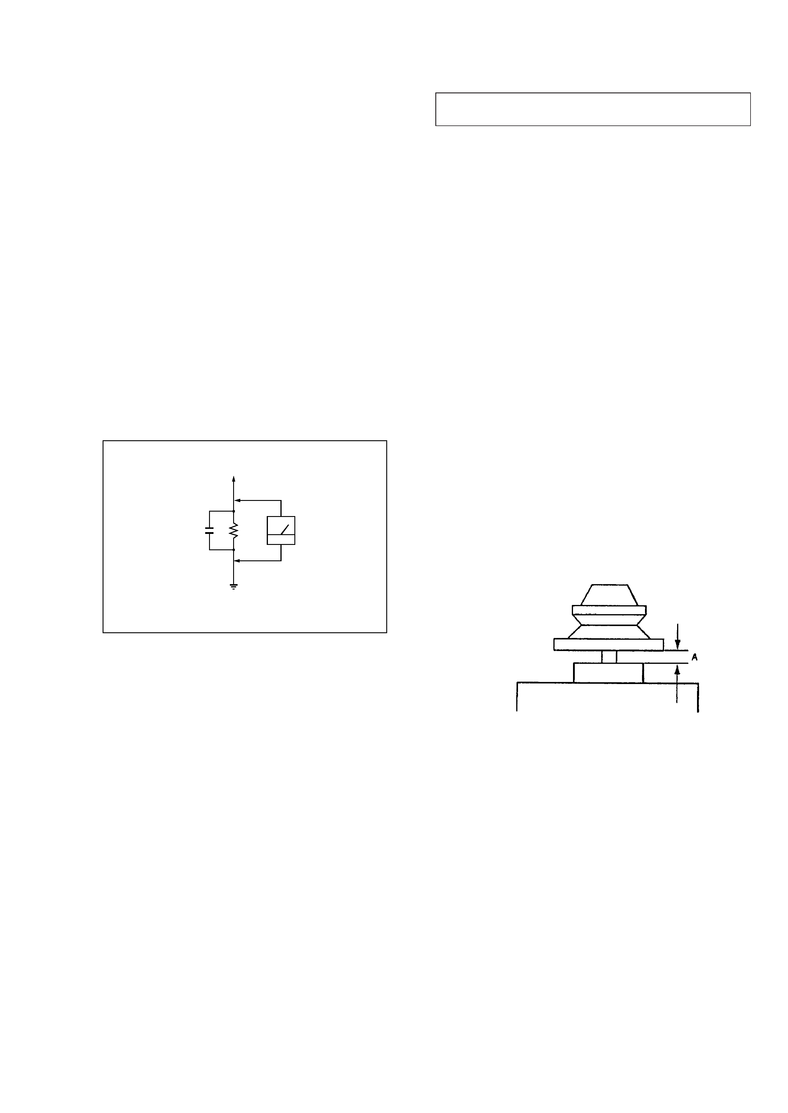
3. Measuring the voltage drop across a resistor by means of a VOM
or battery-operated AC voltmeter. The "limit" indication is 0.75V,
so analog meters must have an accurate low-voltage scale. The
Simpson 250 and Sanwa SH-63Trd are examples of a passive
VOM that is suitable. Nearly all battery operated digital
multimeters that have a 2V AC range are suitable. (See Fig. A)
NOTES ON HANDLING THE OPTICAL PICK-UP BLOCK
OR BASE UNIT
The laser diode in the optical pick-up block may suffer electrostatic
breakdown because of the potential difference generated by the
charged electrostatic load, etc. on clothing and the human body.
During repair, pay attention to electrostatic breakdown and also use
the procedure in the printed matter which is included in the repair
parts.
The flexible board is easily damaged and should be handled with
care.
NOTES ON LASER DIODE EMISSION CHECK
The laser beam on this model is concentrated so as to be focused on
the disc reflective surface by the objective lens in the optical pick-
up block. Therefore, when checking the laser diode emission, ob-
serve more than 30 cm away from the objective lens.
LASER DIODE AND FOCUS SEARCH OPERATION
CHECK
1. Close the lid for CD.
2. Press CD
^ button.
3. Confirm the laser diode emission while observing the objecting
lens. When there is no emission, Auto Power Control circuit or
Optical Pick-up is broken.
Objective lens moves up and down once for the focus search.
AC
voltmeter
(0.75V)
To Exposed Metal
Parts on Set
Earth Ground
0.15
µF
1.5k
Fig. A. Using an AC voltmeter to check AC leakage.
CAUTION DURING WHEN MOUNTING THE PULLEY
FOR THE LOADING MOTOR
Make the following adjustment when mounting the loading motor
(part number : 1-698-999-11) and motor pulley (part number : 2-
627-174-01) of the CD section.
Specification : A = 0.9 to 1.1mm
SECTION 1
SERVICE NOTE
SAFETY-RELATED COMPONENT WARNING!!
COMPONENTS IDENTIFIED BY MARK
! OR DOTTED LINE WITH
MARK
!ON THE SCHEMATIC DIAGRAMS AND IN THE PARTS
LIST ARE CRITICAL TO SAFE OPERATION.
REPLACE THESE COMPONENTS WITH SONY PARTS WHOSE
PART NUMBERS APPEAR AS SHOWN IN THIS MANUAL OR IN
SUPPLEMENTS PUBLISHED BY SONY.
Flexible Circuit Board Repairing
· Keep the temperature of the soldering iron around 270°C during
repairing.
· Do not touch the soldering iron on the same conductor of the
circuit board (within 3 times).
· Be careful not to apply force on the conductor when soldering or
unsoldering.
Notes on chip component replacement
· Never reuse a disconnected chip component.
· Notice that the minus side of a tantalum capacitor may be dam-
aged by heat.
4
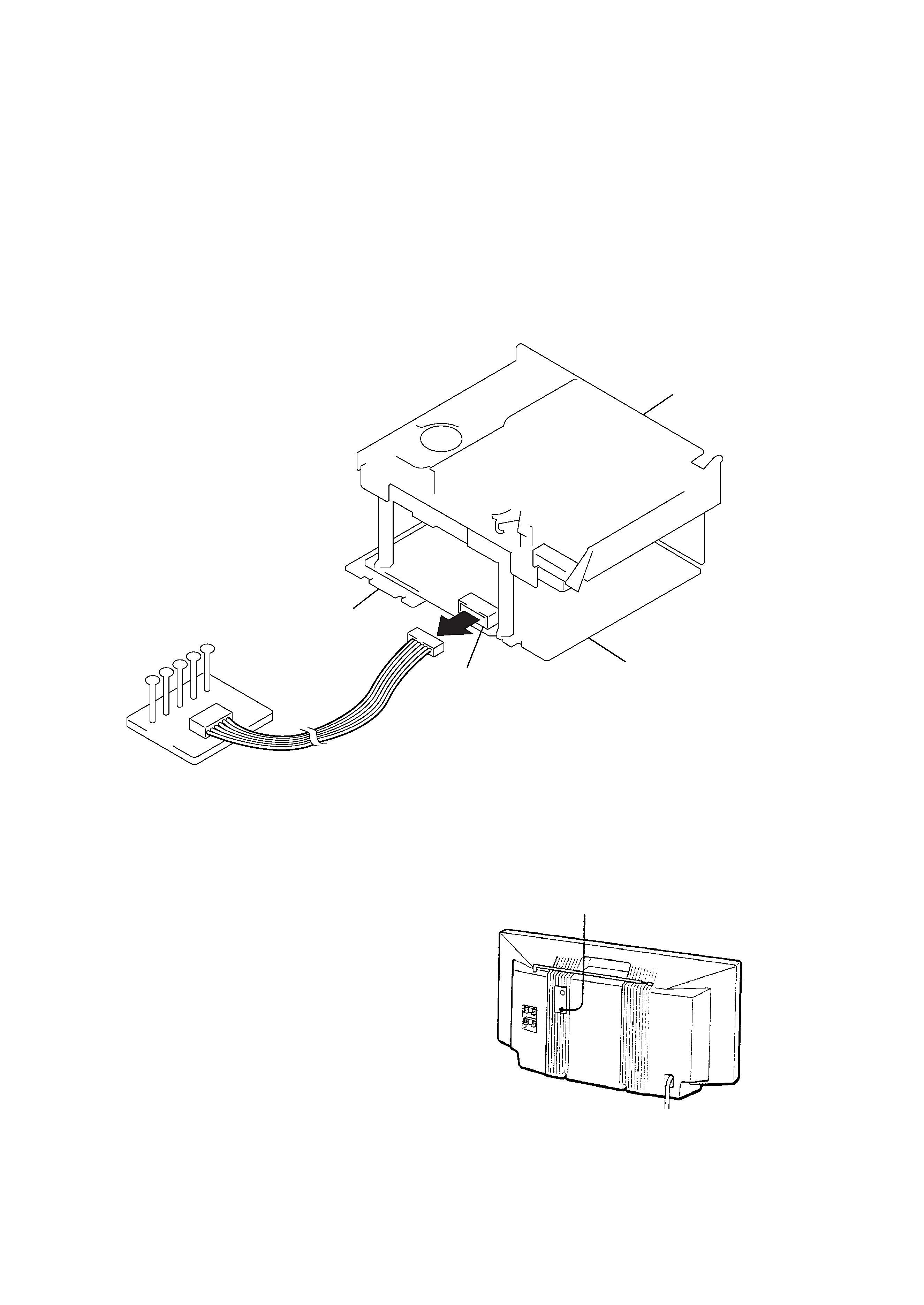
ABOUT THE BD BOARD WAVEFORM CHECKING JIG
The special jig (J-2501-124-A) is highly convenient when check-
ing the waveform of the BD board of the MD section. Pin names
and items to check are as follows:
I+3V : for IOP measurement (check for depleted optical pickup
laser)
IOP
: for IOP measurement (check for depleted optical pickup
laser)
TEO : TRK error signal (traverse adjustment)
VC
: Standard level for checking signals
RF
: RF signal (jitter check)
RESET button
BD board
CN110
DG board
I + 3V
IOP
TEO
VC
RF
Jig
(J-2501-124-A)
MD block section
ABOUT THE HARDWARE RESET
It is possible to reset the system microcomputer by pressing the
RESET button located on the rear with a pointed object. Use this
button when the unit cannot be operated properly due to such prob-
lems as microcomputer errors, etc.
5
SECTION 2
GENERAL
LOCA
TION
AND
FUNCTION
OF
CONTR
OLS
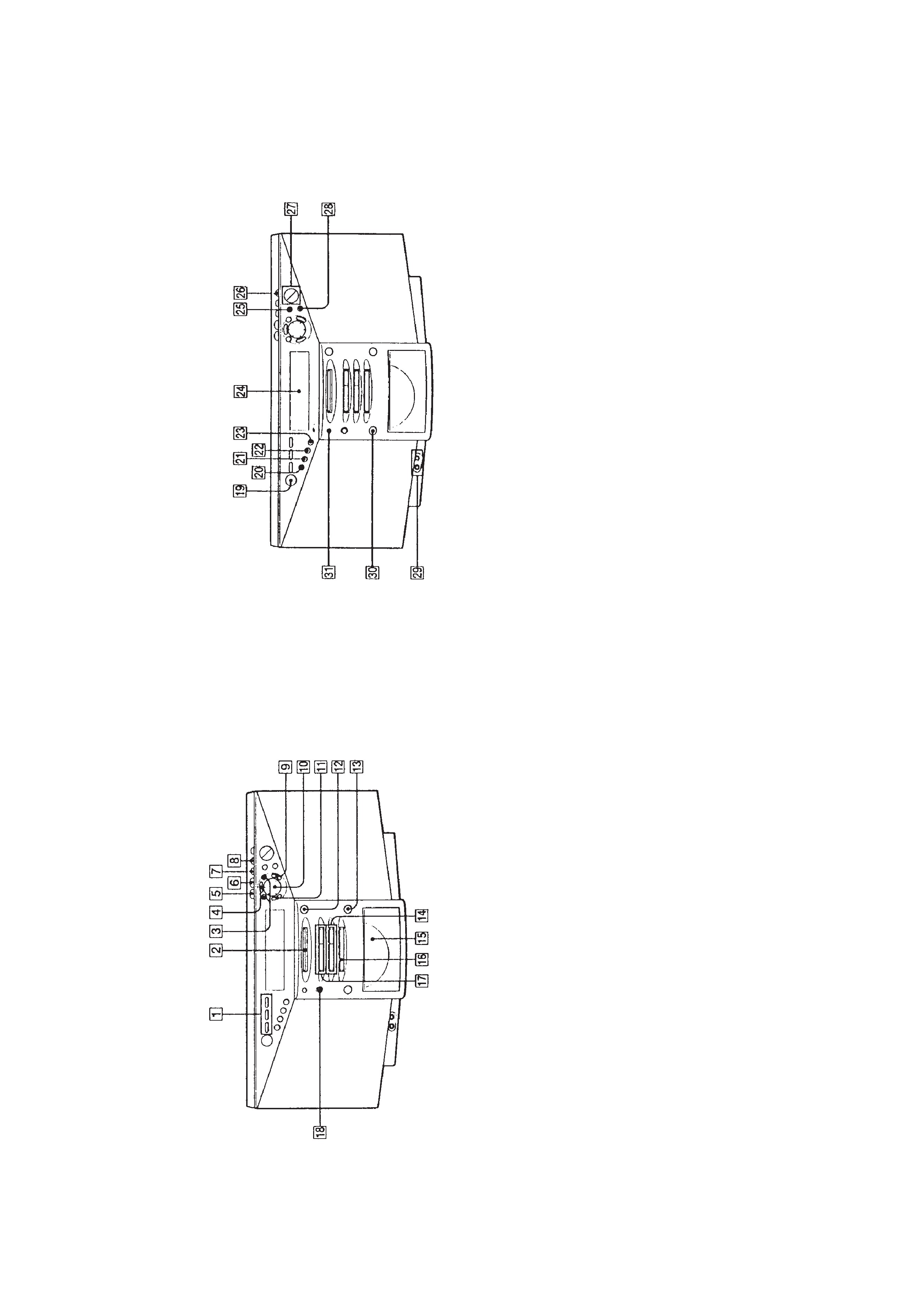
FR
ONT
P
ANEL
:
RADIO
section
1
CD
(
MD
SYNCHRO
REC
button
DISC
ALL
REC
IT
:
T
O
T
O
P
T
O
END
2
MD
insert
section
3
TUNE,
+
·
0
,)
·
i
,
b
utton
4
EDIT
button
5
DELETE
button
6
INSER
T
b
utton
7
A
U
T
O
PRESET·SHUF/PGM
b
utton
8
LINE
LEVEL·MONO/ST·REPEA
T
b
utton
9
ENTER·YES
button
!º
Jog
dial
=
/+
AMS
PRESET
!¡
CANCEL·NO
button
!TM
6
MD
EJECT
button
!£
6
CD
OPEN/CLOSE
button
!¢
CD
operation
buttons
^
(play/pause)
p
(stop)
!
CD
tray
!§
BAND
button
!¶
MD
operation
button
^
(play/pause)
p
(stop)
!·
REC
button
FR
ONT
P
ANEL
:
TIMER
·
COM
section
!ª
PO
WER
b
utton
(US
MODEL)
OPERA
TE
b
utton
(EXCEPT
US
MODEL)
@º
SLEEP
b
utton
@¡
ST
ANDBY
b
utton
@TM
TIMER
b
utton
@£
CLOCK
b
utton
@¢
Displa
y
windo
w
@
BASS/TREBLE
b
utton
@§
MEGA
BASS
b
utton
@¶
V
OLUM
,
+
b
utton
@·
DISPLA
Y
b
utton
@ª
2
(Headphones)
J
a
c
k
(stereo
mini
jac
k)
#º
LINE
b
utton
#¡
Remote
control
receiv
er
section