1
SERVICE MANUAL
US Model
Canadian Model
AEP Model
UK Model
E Model
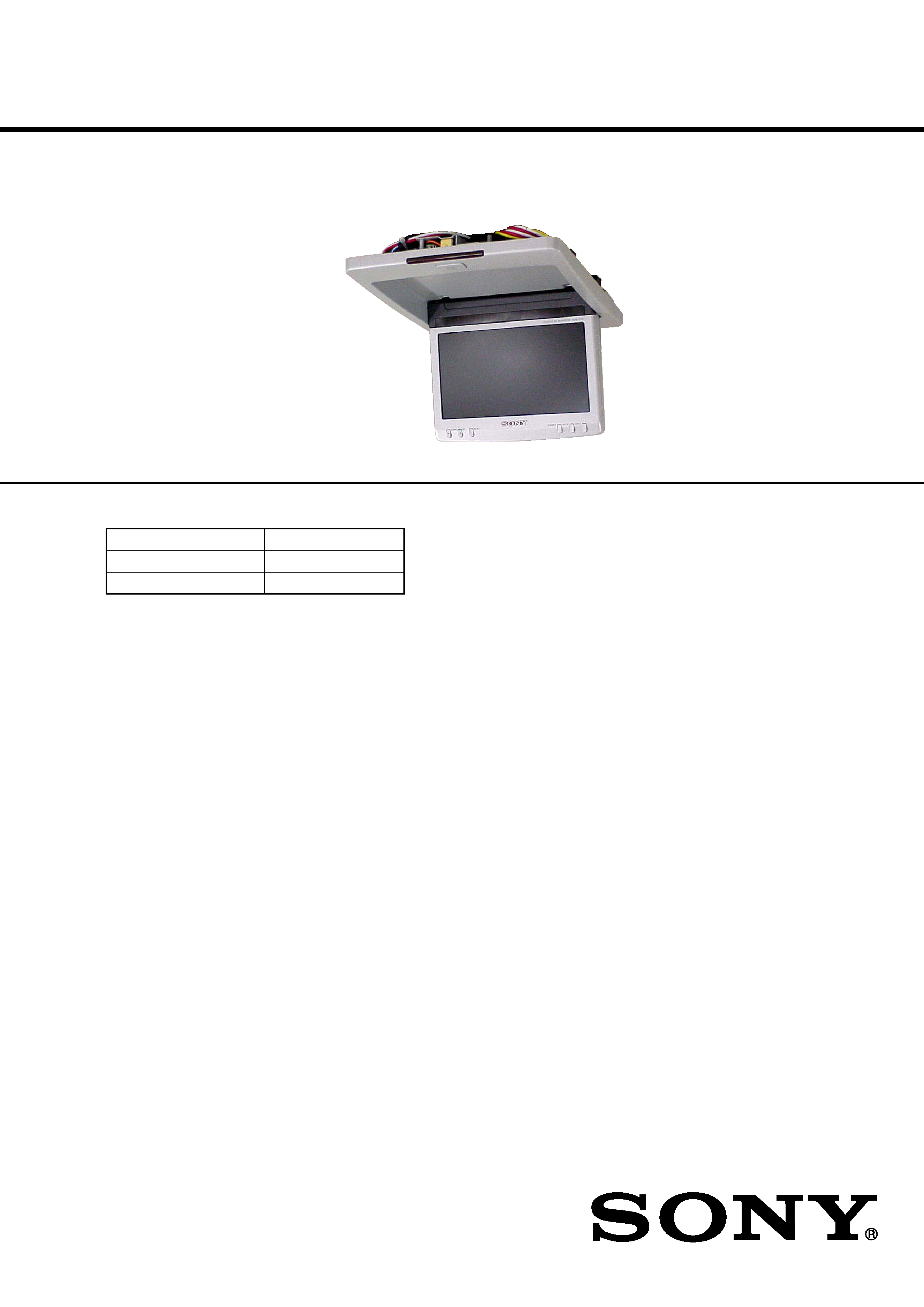
XVM-R75
· This set consists of the following units.
MONITOR
XVM-R75
CONNECTION BOX
XA-117
REMOTE COMMANDER
RM-X123
SPECIFICATIONS
Monitor
System
Liquid crystal color display
Display
Motorized flipdown panel
Drive system
TFT-LCD active matrix
system
Picture size
7 inches wide screen (16:9)
154
× 87 mm, 176 mm
(6 1/8
× 3 1/2 in., 7 in.)
(w/h, d)
Picture segment
336,960 (w 1440
× h 234) dots
Power requirements
12 V DC car battery
(negative ground)
Current drain
Approx. 1.5 A
Dimensions
US, Canadian model:
202
× 45 × 243 mm
(8
× 1 13/16 × 9 5/8 in.)
(w/h/d)
EXCEPT US, Canadian model:
230
× 50 × 270 mm
(w/h/d)
Operating temperature
5 °C 45 °C
(41 °F 113 °F)
Mass
US, Canadian model:
Approx. 1.2 Kg (2 lb 10 oz)
EXCEPT US, Canadian model:
Approx. 1.3 Kg
Connection box XA-117
A/V Output
Output Impedance: less than 220
less than 100 pF
Output Level:
0 dBs ±0.3 dB
(0.775 V rms)
(Vol Max)
Video:
75
1Vp-p
A/V Input
× 3
Input Impedance:
more than 10 K
less than 1000 pF
Input Level:
0 dBs ± 0.3 dB
(0.775 V rms)
Video:
75
1 Vp-p
DC output
7.5 V (max 2 A)
Dimensions
101
× 42 × 73 mm
(4
× 1 11/16 × 2 7/8 in.)
(w/h/d)
Mass
Approx. 150 g (5 oz)
Ver 1.1 2002. 08
9-874-115-02
2002H0400-1
© 2002. 08
OVERHEAD MONITOR
Sony Corporation
e Vehicle Company
Published by Sony Engineering Corporation
Continued on next page

2
TABLE OF CONTENTS
1. GENERAL
Location of Controls ............................................................... 3
Connection diagram ............................................................... 5
2. DISASSEMBLY
2-1. LCD Block Assy ................................................................ 7
2-2. Connectors ......................................................................... 8
2-3. Main Board ........................................................................ 8
2-4. Motor (M1), Micro SW Board ........................................... 9
2-5. Display Board .................................................................... 9
3. DIAGRAMS
3-1. Circuit Boards Location ................................................... 11
3-2. Printed Wiring Board Main Section (1/2) .................... 12
3-3. Printed Wiring Boards Main Section (2/2) .................. 13
3-4. Schematic Diagram Main Section (1/2) ....................... 14
3-5. Schematic Diagram Main Section (2/2) ....................... 15
3-6. Printed Wiring Board Display Section (1/2) ................ 16
3-7. Printed Wiring Board Display Section (2/2) ................ 17
3-8. Schematic Diagram Display Section (1/3) ................... 18
3-9. Schematic Diagram Display Section (2/3) ................... 19
3-10. Schematic Diagram Display Section (3/3) ................... 20
4. EXPLODED VIEWS
4-1. Cover Section-1 ................................................................ 21
4-2. Cover Section-2 ................................................................ 22
4-3. LCD Section ..................................................................... 23
5. ELECTRICAL PARTS LIST ....................................... 24
Notes on Chip Component Replacement
·Never reuse a disconnected chip component.
· Notice that the minus side of a tantalum capacitor may be
damaged by heat.
XVM-R75
SAFETY-RELATED COMPONENT WARNING!!
COMPONENTS IDENTIFIED BY MARK 0 OR DOTTED LINE
WITH MARK 0 ON THE SCHEMATIC DIAGRAMS AND IN
THE PARTS LIST ARE CRITICAL TO SAFE OPERATION.
REPLACE THESE COMPONENTS WITH SONY PARTS WHOSE
PART NUMBERS APPEAR AS SHOWN IN THIS MANUAL OR
IN SUPPLEMENTS PUBLISHED BY SONY.
ATTENTION AU COMPOSANT AYANT RAPPORT
À LA SÉCURITÉ!!
LES COMPOSANTS IDENTIFIÉS PAR UNE MARQUE 0 SUR LES
DIAGRAMMES SCHÉMATIQUES ET LA LISTE DES PIÈCES
SONT CRITIQUES POUR LA SÉCURITÉ DE FONCTIONNEMENT.
NE REMPLACER CES COMPOSANTS QUE PAR DES PIÈCES
SONY DONT LES NUMÉROS SONT DONNÉS DANS CE MANUEL
OU DANS LES SUPPLÉMENTS PUBLIÉS PAR SONY.
Card remote commander RM-X123
Power requirements
CR2025 lithium battery
Operable range
Approx. 2.5 m (8.22 ft.)
Dimensions
56
× 89 × 7 mm
(2 1/4
× 3 5/8 × 9/32 in.)
(w/h/d)
Mass
Approx. 25 g (1 oz)
(including batteries)
Supplied accessories
Connection box XA-117 (1)
Card remote commander RM-X123
(with supplied battery) (1)
Extension cable (5 m) (1)
Power supply cord (1)
DC-DC cord (3 m) (1)
Stereo Mini Plug-to-Plug cable (5 m) (1)
Mounting plate (1)
Screws (4)
Tapping Screws (4)
Cord stopper (1)
Cramper (1)
Operating Instructions (1)
Design and specifications are subject to change
without notice.
·Abbreviation
CND
: Canadian model
3
XVM-R75
SECTION 1
GENERAL
This section is extracted
from instruction manual.
7
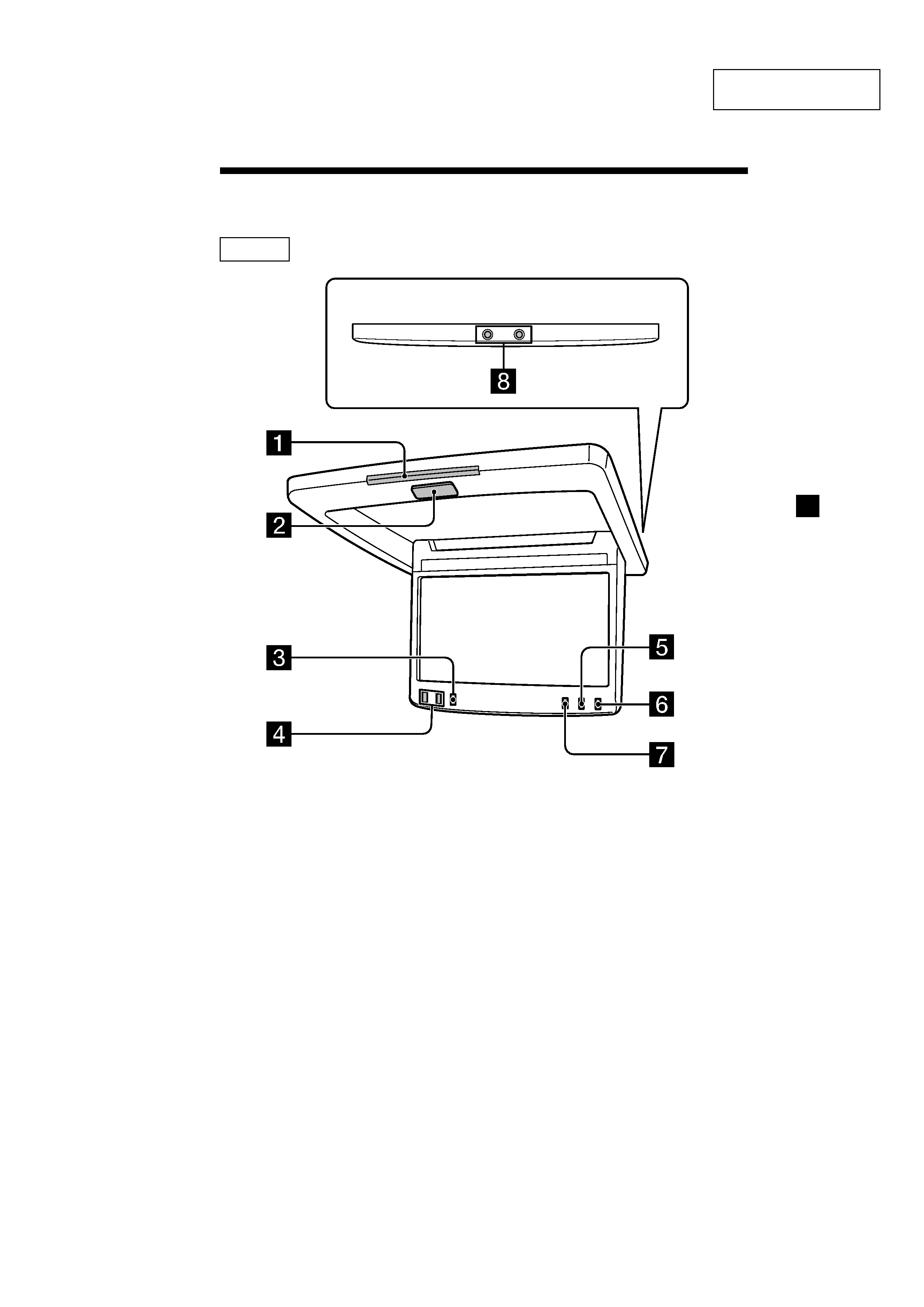
Location of Controls
1 Receptor for the card remote
commander
2 OPEN/CLOSE button 9
Press to open and close the monitor.
3 MENU button 12, 13
Press to adjust the various display
settings.
4 M/m buttons
5 MODE button 10
Press to change the screen mode.
6 INPUT button 11
Press to select the input source.
7 DIMMER button 12, 13
Press to set the dimmer function on
and off.
8 Headphone jacks (stereo mini) 14
Connect headphones to these jacks.
Monitor
continue to next page t
4
XVM-R75
8
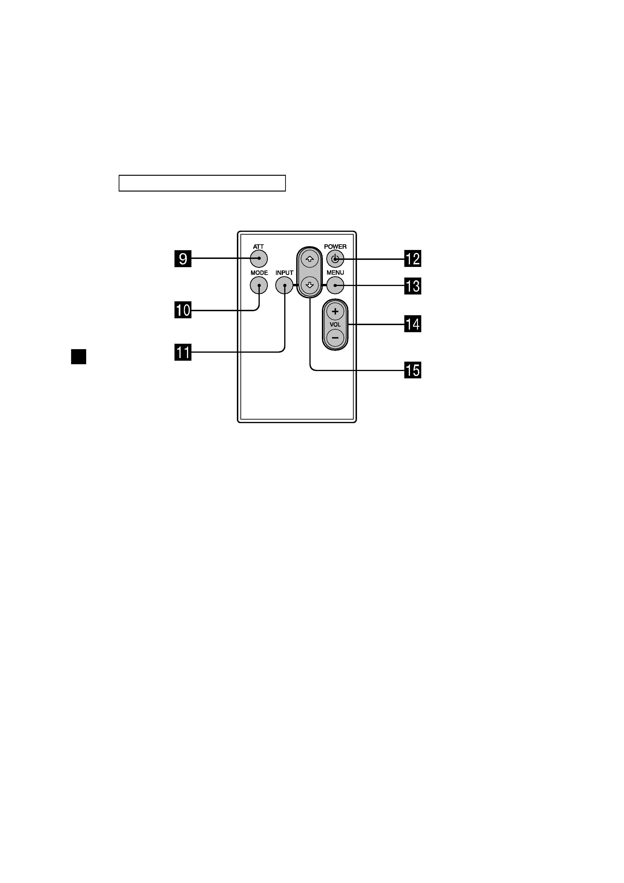
Tip
Refer to "Replacing the lithium battery" for details on how to replace the batteries (page
18).
9 ATT button 14
Press to quickly attenuate the
volume.
0 MODE button 10
Press to change the screen mode.
qa INPUT button 11
Press to select the input source.
qs POWER button 9
qd MENU button 12, 13
Press to adjust the various display
settings.
qf VOL (volume) +/ buttons 14
Press to adjust the volume.
qg F/f buttons
Card remote commander RM-X123
5
XVM-R75
16
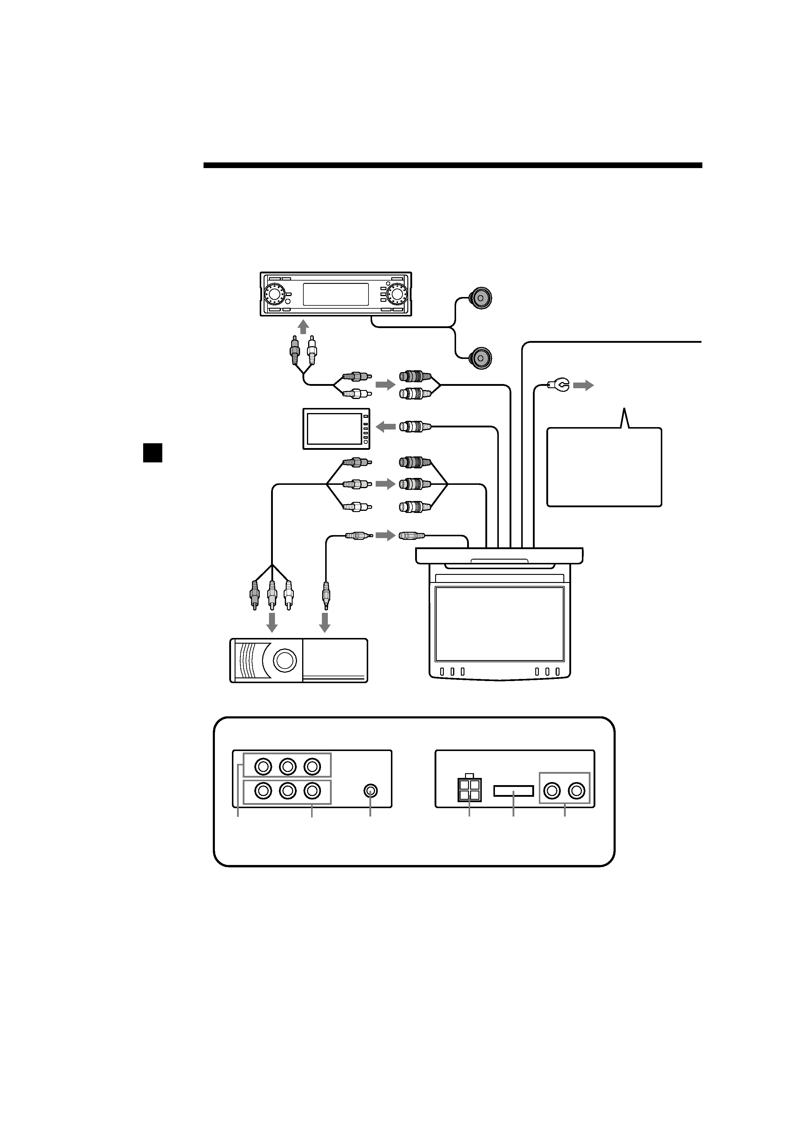
Connection diagram
R
L
V
1
2
L
R
Master unit (optional)
RCA pin cord
(optional)
Audio output
To Speakers/Amplifier/Subwoofer
(optional)
Audio L/R/
Video Input 1
Red
Yellow
White
Stereo Mini jack
Output (IR)
Remote
Commander
Signal
receiver cord
DVD Changer DVX-100 (optional)
Overhead Monitor
(7 wide color LCD Monitor)
* Connection box XA-117
Front
Rear
7.5 V (max 2 A)
DC Output (for
game players)
4 Pin Power
connector
15 Pin
connector
Audio
Outputs
Audio L/R /
Video Input 2
Audio L/R /
Video Input 3
RCA pin cord
(optional)
5 m
To Headrest Monitor
XVM-H6 (optional)
Video output
0.1 m
0.1 m
0.2 m
0.2 m
0.1 m
Refer to the connection diagram for the proper connections.
You can make connections shown in A area. Please ask a qualified technician for the
other connections.
To AUX IN
To a metal surface
of the car chassis
Note
Without a ground,
noise may occur on
pictures.
0.5 m